Page is loading ...

Installation, Operation, and
Maintenance Manual
Model HT 3196 i-FRAME


Table of Contents
1 Introduction and Safety
....................................................................................................................................5
1.1 Introduction................................................................................................................................................ 5
1.1.1 Requesting other information ..........................................................................................................5
1.2 Safety ........................................................................................................................................................5
1.2.1 Safety terminology and symbols ..................................................................................................... 6
1.2.2 Environmental safety.......................................................................................................................7
1.2.3 User safety ......................................................................................................................................7
1.3 Product warranty .....................................................................................................................................10
1.4 ATEX Considerations and Intended Use................................................................................................10
2 Transportation and Storage............................................................................................................................ 15
2.1 Inspect the delivery .................................................................................................................................15
2.1.1 Inspect the package ......................................................................................................................15
2.1.2 Inspect the unit..............................................................................................................................15
2.2 Transportation guidelines ........................................................................................................................ 15
2.2.1 Pump handling .............................................................................................................................. 15
2.2.2 Lifting methods..............................................................................................................................15
2.3 Storage guidelines................................................................................................................................... 18
2.3.1 Pump storage requirements..........................................................................................................18
2.3.2 Frostproofing .................................................................................................................................19
3 Product Description ........................................................................................................................................20
3.1 General description HT 3196 .................................................................................................................20
3.1.1 Part description HT 3196 .............................................................................................................. 21
3.2 General description i-ALERT®2 Equipment Condition Monitor...............................................................22
3.3 Nameplate information ............................................................................................................................23
4 Installation........................................................................................................................................................27
4.1 Pre-installation......................................................................................................................................... 27
4.1.1 Pump location guidelines .............................................................................................................. 27
4.1.2 Foundation requirements .............................................................................................................. 28
4.2 Baseplate-mounting procedures .............................................................................................................29
4.2.1 Prepare the baseplate for mounting..............................................................................................29
4.2.2 Install the baseplate using shims or wedges.................................................................................29
4.2.3 Install the baseplate using jackscrews ..........................................................................................30
4.2.4 Install the baseplate using spring mounting ..................................................................................32
4.2.5 Install the baseplate using stilt mounting ...................................................................................... 33
4.2.6 Baseplate-leveling worksheet ....................................................................................................... 35
4.3 Install the pump, driver, and coupling......................................................................................................36
4.4 Pump-to-driver alignment ........................................................................................................................ 36
4.4.1 Alignment checks ..........................................................................................................................36
4.4.2 Permitted indicator values for alignment checks........................................................................... 37
4.4.3 Alignment measurement guidelines ..............................................................................................37
4.4.4 Attach the dial indicators for alignment ......................................................................................... 37
4.4.5 Pump-to-driver alignment instructions...........................................................................................38
4.4.6 C-face adapter .............................................................................................................................. 41
4.5 Grout the baseplate.................................................................................................................................42
4.6 Piping checklists......................................................................................................................................43
Table of Contents
Model HT 3196 i-FRAME Installation, Operation, and Maintenance Manual 1

4.6.1 General piping checklist ................................................................................................................43
4.6.2 Suction-piping checklist.................................................................................................................45
4.6.3 Discharge piping checklist.............................................................................................................48
5 Commissioning, Startup, Operation, and Shutdown ...................................................................................50
5.1 Preparation for startup............................................................................................................................. 50
5.2 Remove the coupling guard ....................................................................................................................51
5.3 Check the rotation ...................................................................................................................................53
5.4 Impeller-clearance check ........................................................................................................................53
5.4.1 Impeller clearances (3196 and HT 3196)......................................................................................54
5.5 Impeller-clearance setting .......................................................................................................................54
5.5.1 Set the impeller clearance - dial indicator method (all except CV 3196, CV 3198, and LF 3196
size 1x1.5-4) ...................................................................................................................................55
5.5.2 Set the impeller clearance - feeler gauge method (all except CV 3196, CV3198 and LF 3196 size
1x1.5-4)............................................................................................................................................ 56
5.6 Couple the pump and driver .................................................................................................................... 57
5.6.1 Install the coupling guard .............................................................................................................. 58
5.6.2 Bearing lubrication ........................................................................................................................ 63
5.7 Shaft-sealing options...............................................................................................................................65
5.7.1 Mechanical seal options................................................................................................................65
5.7.2 Connection of sealing liquid for mechanical seals ........................................................................ 65
5.7.3 Packed stuffing box option ............................................................................................................65
5.7.4 Connection of sealing liquid for a packed stuffing box ..................................................................66
5.8 Install the shaft guard - if provided ..........................................................................................................66
5.9 Pump priming ..........................................................................................................................................67
5.9.1 Prime the pump with the suction supply above the pump.............................................................67
5.9.2 Prime the pump with the suction supply below the pump ............................................................. 67
5.9.3 Other methods of priming the pump..............................................................................................68
5.10 Start the pump.......................................................................................................................................68
5.11 Activate the i-ALERT® Health Monitor ..................................................................................................69
5.12 i-ALERT®2 Equipment Health Monitor..................................................................................................70
5.13 Pump operation precautions .................................................................................................................70
5.14 Shut down the pump .............................................................................................................................71
5.15 Deactivate the i-ALERT®2 Equipment Health Monitor..........................................................................72
5.16 Reset the i-ALERT®2 Health Monitor ...................................................................................................72
5.17 Make the final alignment of the pump and driver ..................................................................................72
6 Maintenance..................................................................................................................................................... 74
6.1 Maintenance schedule ............................................................................................................................74
6.2 Bearing maintenance ..............................................................................................................................75
6.2.1 Lubricating-oil requirements..........................................................................................................75
6.2.2 Regrease the grease-lubricated bearings .....................................................................................76
6.2.3 Lubricate the bearings after a shutdown period ............................................................................77
6.3 Shaft seal maintenance...........................................................................................................................78
6.3.1 Mechanical-seal maintenance.......................................................................................................78
6.3.2 Packed stuffing-box maintenance .................................................................................................78
6.4 Disassembly ............................................................................................................................................ 79
6.4.1 Disassembly precautions .............................................................................................................. 79
6.4.2 Tools required................................................................................................................................ 80
6.4.3 Drain the pump..............................................................................................................................80
6.4.4 Remove the coupling .................................................................................................................... 80
Table of Contents
2 Model HT 3196 i-FRAME Installation, Operation, and Maintenance Manual

6.4.5 Remove the back pull-out assembly ............................................................................................. 81
6.4.6 Remove the coupling hub ............................................................................................................. 83
6.4.7 Impeller removal............................................................................................................................84
6.4.8 Shaft guard removal (if provided)..................................................................................................86
6.4.9 Seal-chamber cover removal ........................................................................................................ 87
6.4.10 Remove the seal-chamber cover (3196, CV 3196, HT 3196, LF 3196, 3796)............................ 87
6.4.11 Remove the stuffing-box cover (3196, CV 3196, HT 3196, LF 3196, 3796) ............................... 88
6.4.12 Remove the frame adapter (MTi, LTi, XLT-i) ............................................................................... 90
6.4.13 Remove the inboard labyrinth oil seal .........................................................................................90
6.4.14 Power-end disassembly ..............................................................................................................90
6.4.15 Disassemble the bearing frame .................................................................................................. 99
6.4.16 Guidelines for i-ALERT®2 Equipment Health Monitor disposal ................................................ 100
6.4.17 Disassemble the C-face adapter...............................................................................................100
6.5 Pre-assembly inspections .....................................................................................................................101
6.5.1 Replacement guidelines..............................................................................................................101
6.5.2 Shaft and sleeve replacement guidelines ................................................................................... 103
6.5.3 Bearing-frame inspection ............................................................................................................ 104
6.5.4 C-face adapter inspection ........................................................................................................... 105
6.5.5 Seal chamber and stuffing box cover inspection......................................................................... 106
6.5.6 Bearings inspection.....................................................................................................................107
6.5.7 Bearing-housing inspection.........................................................................................................107
6.5.8 Bearing fits and tolerances..........................................................................................................108
6.6 Reassembly........................................................................................................................................... 109
6.6.1 Assemble the rotating element and the bearing frame (STi and MTi)......................................... 109
6.6.2 Assemble the rotating element and the bearing frame (STi and MTi with duplex bearings) ....... 112
6.6.3 Assemble the rotating element and the bearing frame (LTi) ....................................................... 115
6.6.4 Assemble the rotating element and the bearing frame (XLT-i and i17) ....................................... 119
6.6.5 Assemble the rotating element and the bearing frame (XLT-i and i17 with duplex bearings) .....122
6.6.6 Assemble the frame .................................................................................................................... 126
6.6.7 INPRO labyrinth oil seal description............................................................................................130
6.6.8 Assemble the INPRO labyrinth oil seal ....................................................................................... 130
6.6.9 Assemble the C-face adapter......................................................................................................131
6.6.10 Shaft sealing ............................................................................................................................. 131
6.6.11 Shaft guard installation (if provided) .......................................................................................... 137
6.6.12 Install the impeller ..................................................................................................................... 140
6.6.13 Attach the i-ALERT®2 Equipment Health Monitor to the pump ................................................141
6.6.14 Post-assembly checks .............................................................................................................. 142
6.6.15 Reinstall the back pull-out assembly for the HT 3196...............................................................142
6.6.16 Assembly references.................................................................................................................145
6.6.17 Spare parts................................................................................................................................147
6.7 Interchangeability drawings...................................................................................................................148
6.7.1 HT 3196 interchangeability ......................................................................................................... 148
6.8 Lubrication conversion ..........................................................................................................................149
6.8.1 Frame lubrication conversion ......................................................................................................149
6.8.2 Convert from greased-for-life or regreaseable to oil-lubricated bearings.................................... 150
6.8.3 Conversion from flood-oil to pure-oil mist....................................................................................151
6.8.4 Convert from flood oil to regreaseable ........................................................................................152
7 Troubleshooting ............................................................................................................................................153
7.1 Operation troubleshooting ..................................................................................................................... 153
Table of Contents
Model HT 3196 i-FRAME Installation, Operation, and Maintenance Manual 3

7.2 Alignment troubleshooting.....................................................................................................................154
7.3 Assembly troubleshooting .....................................................................................................................154
7.4 i-ALERT®2 Equipment Health Monitor troubleshooting........................................................................155
8 Parts Listings and Cross-Sectionals...........................................................................................................156
8.1 Parts list................................................................................................................................................. 156
9 Other Relevant Documentation or Manuals................................................................................................164
9.1 For additional documentation ................................................................................................................ 164
10 Local ITT Contacts ......................................................................................................................................165
10.1 Regional offices................................................................................................................................... 165
Table of Contents
4 Model HT 3196 i-FRAME Installation, Operation, and Maintenance Manual

1 Introduction and Safety
1.1 Introduction
Purpose of this manual
The purpose of this manual is to provide necessary information for:
•
Installation
• Operation
• Maintenance
CAUTION:
Failure to observe the instructions contained in this manual could result in personal injury
and/or property damage, and may void the warranty. Read this manual carefully before instal-
ling and using the product.
NOTICE:
Save this manual for future reference and keep it readily available.
1.1.1 Requesting other information
Special versions can be supplied with supplementary instruction leaflets. See the sales contract for any
modifications or special version characteristics. For instructions, situations, or events that are not consid-
ered in this manual or in the sales documents, please contact the nearest ITT representative.
Always specify the exact product type and serial number when requesting technical information or spare
parts.
1.2 Safety
WARNING:
•
Risk of serious personal injury. Applying heat to impellers, propellers, or their retaining
devices can cause trapped liquid to rapidly expand and result in a violent explosion. This
manual clearly identifies accepted methods for disassembling units. These methods must
be adhered to. Never apply heat to aid in their removal unless explicitly stated in this
manual.
• The operator must be aware of the pumpage and take appropriate safety precautions to
prevent physical injury.
• Risk of serious injury or death. If any pressure-containing device is over-pressurized, it
can explode, rupture, or discharge its contents. It is critical to take all necessary meas-
ures to avoid over-pressurization.
• Risk of death, serious personal injury, and property damage. Installing, operating, or
maintaining the unit using any method not prescribed in this manual is prohibited. Prohib-
ited methods include any modification to the equipment or use of parts not provided by
ITT. If there is any uncertainty regarding the appropriate use of the equipment, please
contact an ITT representative before proceeding.
1 Introduction and Safety
Model HT 3196 i-FRAME Installation, Operation, and Maintenance Manual 5

• If the pump or motor is damaged or leaking, electric shock, fire, explosion, liberation of
toxic fumes, physical harm, or environmental damage may result. Do not operate the unit
until the problem has been corrected or repaired.
• Risk of serious personal injury or property damage. Dry running may cause rotating parts
within the pump to seize to non-moving parts. Do not run dry.
• Risk of death, serious personal injury, and property damage. Heat and pressure buildup
can cause explosion, rupture, and discharge of pumpage. Never operate the pump with
suction and/or discharge valves closed.
• Running a pump without safety devices exposes operators to risk of serious personal in-
jury or death. Never operate a unit unless appropriate safety devices (guards, etc.) are
properly installed. See specific information about safety devices in other sections of this
manual.
CAUTION:
•
Risk of injury and/or property damage. Operating a pump in an inappropriate application
can cause over pressurization, overheating, and/or unstable operation. Do not change the
service application without the approval of an authorized ITT representative.
1.2.1 Safety terminology and symbols
About safety messages
It is extremely important that you read, understand, and follow the safety messages and regulations
carefully before handling the product. They are published to help prevent these hazards:
•
Personal accidents and health problems
• Damage to the product
• Product malfunction
Hazard levels
Hazard level Indication
DANGER:
A hazardous situation which, if not avoided, will result in death or seri-
ous injury
WARNING:
A hazardous situation which, if not avoided, could result in death or
serious injury
CAUTION:
A hazardous situation which, if not avoided, could result in minor or
moderate injury
NOTICE:
• A potential situation which, if not avoided, could result in unde-
sirable conditions
•
A practice not related to personal injury
Hazard categories
Hazard categories can either fall under hazard levels or let specific symbols replace the ordinary hazard
level symbols.
Electrical hazards are indicated by the following specific symbol:
1.2 Safety
6 Model HT 3196 i-FRAME Installation, Operation, and Maintenance Manual

ELECTRICAL HAZARD:
These are examples of other categories that can occur. They fall under the ordinary hazard levels and
may use complementing symbols:
•
Crush hazard
• Cutting hazard
• Arc flash hazard
1.2.1.1 The Ex symbol
The Ex symbol indicates safety regulations for Ex-approved products when used in atmospheres that are
potentially explosive or flammable.
1.2.2 Environmental safety
The work area
Always keep the station clean to avoid and/or discover emissions.
W
aste and emissions regulations
Observe these safety regulations regarding waste and emissions:
• Appropriately dispose of all waste.
• Handle and dispose of the processed liquid in compliance with applicable environmental regula-
tions.
• Clean up all spills in accordance with safety and environmental procedures.
• Report all environmental emissions to the appropriate authorities.
WARNING:
If the product has been contaminated in any way
, such as from toxic chemicals or nuclear radi-
ation, do NOT send the product to ITT until it has been properly decontaminated and advise
ITT of these conditions before returning.
Electrical installation
For electrical installation recycling requirements, consult your local electric utility
.
1.2.2.1 Recycling guidelines
Always follow local laws and regulations regarding recycling.
1.2.3 User safety
General safety rules
These safety rules apply:
1.2 Safety
Model HT 3196 i-FRAME Installation, Operation, and Maintenance Manual 7

• Always keep the work area clean.
• Pay attention to the risks presented by gas and vapors in the work area.
• Avoid all electrical dangers. Pay attention to the risks of electric shock or arc flash hazards.
• Always bear in mind the risk of drowning, electrical accidents, and burn injuries.
Safety equipment
Use safety equipment according to the company regulations. Use this safety equipment within the work
area:
• Hardhat
• Safety goggles, preferably with side shields
• Protective shoes
• Protective gloves
• Gas mask
• Hearing protection
• First-aid kit
• Safety devices
Electrical connections
Electrical connections must be made by certified electricians in compliance with all international, nation-
al, state, and local regulations. For more information about requirements, see sections dealing specifical-
ly with electrical connections.
Noise
WARNING:
Sound pressure levels may exceed 80 dbA in operating process plants. Clear visual warnings
or other indicators should be available to those entering an area with unsafe noise levels. Per-
sonnel should wear appropriate hearing protection when working on or around any equipment,
including pumps. Consider limiting personnel’
s exposure time to noise or, where possible, en-
closing equipment to reduce noise. Local law may provide specific guidance regarding expo-
sure of personnel to noise and when noise exposure reduction is required.
Temperature
WARNING:
Equipment and piping surfaces may exceed 130ºF (54ºC) in operating process plants. Clear
visual warnings or other indicators should alert personnel to surfaces that may reach a poten-
tially unsafe temperature. Do not touch hot surfaces. Allow pumps operating at a high tempera-
ture to cool suf
ficiently before performing maintenance. If touching a hot surface cannot be
avoided, personnel should wear appropriate gloves, clothing, and other protective gear as nec-
essary. Local law may provide specific guidance regarding exposure of personnel to unsafe
temperatures.
1.2.3.1 Precautions before work
Observe these safety precautions before you work with the product or are in connection with the product:
•
Provide a suitable barrier around the work area, for example, a guard rail.
• Make sure that all safety guards are in place and secure.
• Make sure that you have a clear path of retreat.
1.2 Safety
8 Model HT 3196 i-FRAME Installation, Operation, and Maintenance Manual

• Make sure that the product cannot roll or fall over and injure people or damage property.
• Make sure that the lifting equipment is in good condition.
• Use a lifting harness, a safety line, and a breathing device as required.
• Allow all system and pump components to cool before you handle them.
• Make sure that the product has been thoroughly cleaned.
• Disconnect and lock out power before you service the pump.
• Check the explosion risk before you weld or use electric hand tools.
1.2.3.2 Precautions during work
Observe these safety precautions when you work with the product or are in connection with the product:
CAUTION:
Failure to observe the instructions contained in this manual could result in personal injury
and/or property damage, and may void the warranty
. Read this manual carefully before instal-
ling and using the product.
• Never work alone.
•
Always wear protective clothing and hand protection.
• Stay clear of suspended loads.
• Always lift the product by its lifting device.
• Beware of the risk of a sudden start if the product is used with an automatic level control.
• Beware of the starting jerk, which can be powerful.
• Rinse the components in water after you disassemble the pump.
• Do not exceed the maximum working pressure of the pump.
• Do not open any vent or drain valve or remove any plugs while the system is pressurized. Make
sure that the pump is isolated from the system and that pressure is relieved before you disassem-
ble the pump, remove plugs, or disconnect piping.
• Never operate a pump without a properly installed coupling guard.
1.2.3.3 Hazardous liquids
The product is designed for use in liquids that can be hazardous to your health. Observe these rules
when you work with the product:
• Make sure that all personnel who work with biologically hazardous liquids are vaccinated against
diseases to which they may be exposed.
• Observe strict personal cleanliness.
• A small amount of liquid will be present in certain areas like the seal chamber.
1.2.3.4 Wash the skin and eyes
1. Follow these procedures for chemicals or hazardous fluids that have come into contact with your
eyes or your skin:
Condition Action
Chemicals or hazardous fluids
in eyes
1. Hold your eyelids apart forcibly with your fingers.
2.
Rinse the eyes with eyewash or running water for at least 15 minutes.
3. Seek medical attention.
1.2 Safety
Model HT 3196 i-FRAME Installation, Operation, and Maintenance Manual 9

Condition Action
Chemicals or hazardous fluids
on skin
1. Remove contaminated clothing.
2.
Wash the skin with soap and water for at least 1 minute.
3. Seek medical attention, if necessary.
1.3 Product warranty
Coverage
ITT undertakes to remedy faults in products from ITT under these conditions:
•
The faults are due to defects in design, materials, or workmanship.
• The faults are reported to an ITT representative within the warranty period.
• The product is used only under the conditions described in this manual.
• The monitoring equipment incorporated in the product is correctly connected and in use.
• All service and repair work is done by ITT-authorized personnel.
• Genuine ITT parts are used.
• Only Ex-approved spare parts and accessories authorized by ITT are used in Ex-approved prod-
ucts.
Limitations
The warranty does not cover faults caused by these situations:
• Deficient maintenance
• Improper installation
• Modifications or changes to the product and installation made without consulting ITT
• Incorrectly executed repair work
• Normal wear and tear
ITT assumes no liability for these situations:
• Bodily injuries
• Material damages
• Economic losses
Warranty claim
ITT products are high-quality products with expected reliable operation and long life. However, should
the need arise for a warranty claim, then contact your ITT representative.
1.4
ATEX Considerations and Intended Use
Special care must be taken in potentially explosive environments to ensure that the equipment is proper-
ly maintained. This includes but is not limited to:
Follow these special handling instructions if you have an Ex-approved unit.
1.3 Product warranty
10 Model HT 3196 i-FRAME Installation, Operation, and Maintenance Manual

The coupling guard used in an ATEX classified environment must be properly certified and
must be constructed from a spark resistant material.
Personnel requirements
These are the personnel requirements for Ex-approved products in potentially explosive atmospheres:
•
All work on the product must be carried out by certified electricians and ITT-authorized mechanics.
Special rules apply to installations in explosive atmospheres.
• All users must know about the risks of electric current and the chemical and physical characteristics
of the gas, the vapor, or both present in hazardous areas.
• Any maintenance for Ex-approved products must conform to international and national standards
(for example, EN 60079-17).
ITT disclaims all responsibility for work done by untrained and unauthorized personnel.
Product and product handling requirements
These are the product and product handling requirements for Ex-approved products in potentially explo-
sive atmospheres:
• Only use the product in accordance with the approved motor data.
• The Ex-approved product must never run dry during normal operation. Dry running during service
and inspection is only permitted outside the classified area.
• Before you start work on the product, make sure that the product and the control panel are isolated
from the power supply and the control circuit, so they cannot be energized.
• Do not open the product while it is energized or in an explosive gas atmosphere.
• Make sure that thermal contacts are connected to a protection circuit according to the approval
classification of the product, and that they are in use.
• Intrinsically safe circuits are normally required for the automatic level-control system by the level
regulator if mounted in zone 0.
• The yield stress of fasteners must be in accordance with the approval drawing and the product
specification.
• Do not modify the equipment without approval from an authorized ITT representative.
• Only use parts that are provided by an authorized ITT representative.
Description of ATEX
The ATEX directives are a specification enforced in Europe for electrical and non-electrical equipment
installed in Europe. ATEX deals with the control of potentially explosive atmospheres and the standards
of equipment and protective systems used within these atmospheres. The relevance of the ATEX re-
quirements is not limited to Europe. You can apply these guidelines to equipment installed in any poten-
tially explosive atmosphere.
Guidelines for compliance
Compliance is fulfilled only when you operate the unit within its intended use. Do not change the condi-
tions of the service without the approval of an ITT representative. When you install or maintain explosion
proof products, always comply with the directive and applicable standards (for example, IEC/EN
60079-14).
1. Monitoring the pump frame and liquid end temperature.
2. Maintaining proper bearing lubrication.
1.4 ATEX Considerations and Intended Use
Model HT 3196 i-FRAME Installation, Operation, and Maintenance Manual 11

3. Ensuring that the pump is operated in the intended hydraulic range.
The ATEX conformance is only applicable when the pump unit is operated within its intended use. Oper-
ating, installing or maintaining the pump unit in any way that is not covered in the Instruction, Operation,
and Maintenance manual (IOM) can cause serious personal injury or damage to the equipment. This in-
cludes any modification to the equipment or use of parts not provided by ITT Goulds Pumps. If there is
any question regarding the intended use of the equipment, please contact an ITT Goulds representative
before proceeding.
Current IOMs are available at https://www.gouldspumps.com/en-US/Tools-and-Resources/Literature/
IOMs/ or from your local ITT Goulds Pumps Sales representative.
All pumping unit (pump, seal, coupling, motor and pump accessories) certified for use in an ATEX classi-
fied environment, are identified by an ATEX tag secured to the pump or the baseplate on which it is
mounted. A typical tag would look like this:
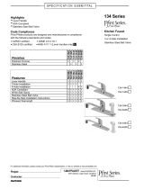
Figure 1: Typical ATEX pump nameplate
The CE and the Ex designate the A
TEX compliance. The code below reads as follows:
Table 1: Temperature class definitions
Code Maximum permissible surface tem-
perature in °C | °F
Maximum permissible liquid tempera-
ture in °C | °F
T1 440 | 824 372 | 700
T2 290 | 554 267 | 513
T3 195 | 383 172 | 342
T4 130 | 266 107 | 225
T5 Option not available Option not available
T6 Option not available Option not available
* Maximum liquid temperature may be limited by the pump model and order specific options. T
able 1:
Temperature class definitions on page 12 is for the purpose of determining T'x' code for ATEX applica-
tions with liquid temperatures exceeding 107ºC | 225ºF.
The code classification marked on the equipment must be in accordance with the specified area where
the equipment will be installed. If it is not, do not operate the equipment and contact your ITT Goulds
Pumps sales representative before proceeding.
ISO 80079-37:2016 Section 5.7
Recommended bearing replacement interval (based on L10 life) = 17,520 hours of operation.
WARNING:
•
When equipment/pumping unit is installed/operated in a potentially explosive atmosphere,
the instructions after the Ex symbol must be followed and equipment must be installed in
accordance with the following instructions. Personal injury and/or equipment damage
from an explosion may occur if these instructions are not followed. If there is any question
1.4 ATEX Considerations and Intended Use
12 Model HT 3196 i-FRAME Installation, Operation, and Maintenance Manual

regarding these requirements or if the equipment is to be modified, please contact a
Goulds representative before proceeding.
• Particular care must be taken when the electrical power source to the equipment is ener-
gized.
• Improper impeller adjustment could cause contact between the rotating and stationary
parts, resulting in a spark and heat generation.
• Lock out driver power to prevent electric shock, accidental start-up and physical injury.
• NEVER start pump without proper prime (all models), or proper liquid level in self-priming
pumps (Model 3796 and SP3298).
• All equipment being installed must be properly grounded to prevent unexpected static
electric discharge. This includes ensuring that the PFA lined pumps (Model 3198), ETFE
lined pumps (Model 3298, SP3298, V3298), and the non-metallic liquid end pumps (Mod-
el NM3196) are pumping fluids that are conductive. If not, a static electric discharge may
occur when the pump is drained and disassembled for maintenance purposes
• When pumping fluids with conductivity less than 1000 ps/m follow IEC TS 60079 32-1
guidelines.
• Alignment procedures must be followed to prevent unintended contact of rotating parts.
Follow coupling manufacturer’s installation and operation procedures.
• When installing in a potentially explosive environment, ensure that the motor and acces-
sories are properly certified.
• The impeller clearance setting procedure must be followed. Improperly setting the clear-
ance or not following any of the proper procedures can result in sparks, unexpected heat
generation and equipment damage.
• The impeller and wear ring clearance setting procedures must be followed. Improperly
setting the clearance or not following any of the proper procedures can result in sparks,
unexpected heat generation and equipment damage.
• Service temperature in an ATEX classified environment is limited to the area classification
specified on the ATEX tag affixed to the pump (reference Table 1 in the Safety section for
ATEX classifications).
• The coupling used in an ATEX classified environment must be properly certified.
• The coupling guard used in an ATEX classified environment must be constructed from a
non-sparking material.
• Bearings must be lubricated properly in order to prevent excess heat generation, sparks
and premature failure.
• The mechanical seal used in an ATEX classified environment must be properly certified.
• The mechanical seal must have an appropriate seal flush system. Failure to do so will re-
sult in excess heat generation and seal failure.
• Packed Stuffing Boxes and/or Dynamic Seals are not allowed in an ATEX classified envi-
ronment.
• Pumps that are not self-priming must be fully primed at all times during operation. The
only model lines that are self-priming is the 3796 and SP3298.
• Pumps must be fully primed at all times during operation.
• The preventive maintenance section must be adhered to in order to keep the applicable
ATEX classification of the equipment. Failure to follow these procedures will void the
ATEX classification for the equipment. Bearing replacement intervals are given in the spe-
cific pump model IOM.
• Inspection intervals should be shortened appropriately if the pumpage is abrasive and/or
corrosive, or if the environment is classified as potentially explosive.
• Throughout this section on bearing lubrication, different pumpage temperatures are listed.
If the equipment is ATEX certified and the listed temperature exceeds the applicable
1.4 ATEX Considerations and Intended Use
Model HT 3196 i-FRAME Installation, Operation, and Maintenance Manual 13

value shown in Table 1 under SAFETY, then that temperature is not valid. Should this sit-
uation occur, please consult with your ITT/Goulds representative.
• Cooling systems, such as those for bearing lubrication, mechanical seal systems, etc.,
where provided, must be operating properly to prevent excess heat generation, sparks
and premature failure.
• Rotate shaft by hand to ensure it rotates smoothly and there is no rubbing which could
lead to excess heat generation, sparks and premature failure.
• Flange loads from the piping system, including those from thermal expansion of the pip-
ing, must not exceed the limits of the pump. Casing deformation can result in contact with
rotating parts which can result in excess heat generation, sparks and premature failure.
• Ensure that pump and systems are free of foreign objects before operating and that ob-
jects cannot enter the pump during operation. Foreign objects in the pumpage or piping
system can cause blockage of flow which can result in excess heat generation, sparks
and premature failure.
• Do not insulate or allow the bearing housings to accumulate a dust layer as this can result
in excess heat generation, sparks and premature failure.
• Check for magnetism on the pump shaft and demagnetize the shaft if there is any detect-
able magnetism. Magnetism will attract ferritic objects to the impeller, seals and bearings
which can result in excess heat generation, sparks and premature failure.
• Leakage of process liquid may result in creation of an explosive atmosphere. Ensure the
materials of the pump casing, impeller, shaft, sleeves, gaskets and seals are compatible
with the process liquid.
• Leakage of process liquid may result in creation of an explosive atmosphere. Follow all
pump and seal assembly procedures.
• A buildup of gases within the pump, sealing system and or process piping system may
result in an explosive environment within the pump or process piping system. Ensure
process piping system, pump and sealing system are properly vented prior to operation.
• Sealing systems that are not self purging or self venting, such as plan 23, require manual
venting prior to operation. Failure to do so will result in excess heat generation and seal
failure.
• Do not apply additional paint or coatings to the pump when in an ATEX environment.
Static electric discharge can be initiated when contacting or rubbing surfaces with exces-
sive coating thickness.
• Potential electrostatic charging hazard. Do not rub, clean, or blast equipment with dry
cloth or dry media.
• Stray electrical currents may ignite explosive atmospheres. Ensure drives are certified for
variable frequency drive operation by the manufacturer.
• User shall observe necessity of using a safety device, such as a flame arrestor, to prevent
flame entering or leaving the pump sump, tank, or barrel when applicable.
• For variable speed motor applications, the electric motor must be specified with shaft
grounding and used with a conductive type coupling suitable for the area classification.
• In plants or pumps with cathodic corrosion protection, a small current constantly flows
through the construction. This is not permissible on the complete pump or partially-as-
sembled machinery without further precautions being taken. ITT should be consulted in
this context.
1.4 ATEX Considerations and Intended Use
14 Model HT 3196 i-FRAME Installation, Operation, and Maintenance Manual

2 Transportation and Storage
2.1 Inspect the delivery
2.1.1 Inspect the package
1.
Inspect the package for damaged or missing items upon delivery.
2. Note any damaged or missing items on the receipt and freight bill.
3. File a claim with the shipping company if anything is out of order.
If the product has been picked up at a distributor, make a claim directly to the distributor.
2.1.2 Inspect the unit
1. Remove packing materials from the product.
Dispose of all packing materials in accordance with local regulations.
2. Inspect the product to determine if any parts have been damaged or are missing.
3. If applicable, unfasten the product by removing any screws, bolts, or straps.
For your personal safety, be careful when you handle nails and straps.
4. Contact your sales representative if anything is out of order.
2.2 Transportation guidelines
2.2.1 Pump handling
WARNING:
Dropping, rolling or tipping units, or applying other shock loads, can cause property damage
and/or personal injury. Ensure that the unit is properly supported and secure during lifting and
handling.
CAUTION:
Risk of injury or equipment damage from use of inadequate lifting devices. Ensure lifting devi-
ces (such as chains, straps, forklifts, cranes, etc.) are rated to suf
ficient capacity.
2.2.2 Lifting methods
WARNING:
•
Risk of serious personal injury or equipment damage. Proper lifting practices are critical
to safe transport of heavy equipment. Ensure that practices used are in compliance with
all applicable regulations and standards.
• Safe lifting points are specifically identified in this manual. It is critical to lift the equipment
only at these points. Integral lifting eyes or eye bolts on pump and motor components are
intended for use in lifting the individual components only.
• Lifting and handling heavy equipment poses a crush hazard. Use caution during lifting
and handling and wear appropriate Personal Protective Equipment (PPE, such as steel-
toed shoes, gloves, etc.) at all times. Seek assistance if necessary.
2 Transportation and Storage
Model HT 3196 i-FRAME Installation, Operation, and Maintenance Manual 15

Table 2: Methods
Pump type Lifting method
Bare pump without lifting handles Use a suitable sling attached properly to solid points like the casing, the flang-
es, or the frames.
A bare pump with lifting handles Lift the pump by the handles.
A base-mounted pump Use slings under the pump casing and the drive unit, or under the base rails.
Examples
Figure 2: Example of a proper lifting method
Figure 3: Example of a proper lifting method
NOTICE:
Do not use this method to lift a Polyshield ANSI Combo with the pump and motor mounted.
These items are not designed to handle the heavy weight of the Polyshield system. Doing so
may result in equipment damage.
2.2 Transportation guidelines
16 Model HT 3196 i-FRAME Installation, Operation, and Maintenance Manual

Figure 4: Example of a proper lifting method
NOTICE:
Do not use this method to lift a Polyshield ANSI Combo with the pump and motor mounted.
These items are not designed to handle the heavy weight of the Polyshield system. Doing so
may result in equipment damage.
Figure 5: Example of a proper lifting method
NOTICE:
When lifting a unit for which a strap cannot be secured at the suction flange, secure the strap
through the frame/frame adapter
. Securing at the frame adapter will prevent slipping of the
strap and possible equipment damage.
2.2 Transportation guidelines
Model HT 3196 i-FRAME Installation, Operation, and Maintenance Manual 17

Figure 6: Example of a proper lifting method with a strap secured around the frame adapter
Figure 7: Example of offset overhead motor mount pump proper lifting method
2.3 Storage guidelines
2.3.1 Pump storage requirements
Storage requirements depend on the amount of time that you store the unit. The normal packaging is
designed only to protect the unit during shipping.
Length of time in storage Storage requirements
Upon receipt/short-term (less than six
months)
• Store in a covered and dry location.
•
Store the unit free from dirt and vibrations.
Long-term (more than six months) • Store in a covered and dry location.
•
Store the unit free from heat, dirt, and vibrations.
• Rotate the shaft by hand several times at least every three months.
2.3 Storage guidelines
18 Model HT 3196 i-FRAME Installation, Operation, and Maintenance Manual
/