Page is loading ...

Control panel for 24 V gearmotors
ZLJ24
ZLJ24Z
INSTALLATION MANUAL
FA01315-EN
EN English

p. 2 - Manual FA01315-EN - 01/2020 - © CAME S.p.A. - The contents of this manual may be changed, at any time, and without notice. - Original instructions
GENERAL PRECAUTIONS FOR INSTALLERS
Important safety instructions.
Please follow all of these instructions. Improper installation may cause
serious bodily harm.
Before continuing, please also read the general precautions for users.
Only use this product for its intended purpose. Any other use is hazardous. •
The manufacturer cannot be held liable for any damage caused by improper,
unreasonable or erroneous use. • This product has been designed to be assembled
to partly completed machinery and/or equipment so as to build machinery as
regulated by the Machinery Directive 2006/42/EC. • The final installation must
comply with the Machinery Directive (2006/42/EC) and the European reference
standards in force. • The manufacturer declines any liability for using non-original
products, which would also void the warranty. • All operations indicated in this
manual must be carried out exclusively by skilled and qualified personnel and in
full compliance with the regulations in force. • The device must be installed, wired,
connected and tested according to good professional practice, in compliance
with the standards and laws in force. • Make sure the mains power supply
is disconnected during all installation procedures. • All the components (e.g.
actuators, photocells and sensitive edges) needed for the final installation to comply
with the Machinery Directive (2006/42/EC) and with the reference harmonised
technical standards are specified in the general CAME product catalogue or on the
website www.came.com. • Check that the temperature ranges given are suitable
for the installation site. • Make sure that no direct jets of water can wet the product
at the installation site (sprinklers, water cleaners, etc.). • Make sure you have set
up a suitable dual-pole cut-o device along the power supply that is compliant with
the installation rules. It should completely cut o the power supply according to
category III surcharge conditions. • Demarcate the entire site properly to prevent
unauthorised personnel from entering, especially minors. • Use suitable protection
to prevent any mechanical hazards due to persons loitering within the operating
range of the operator.

p. 3 - Manual FA01315-EN - 01/2020 - © CAME S.p.A. - The contents of this manual may be changed, at any time, and without notice. - Original instructions
• The electrical cables must pass through special pipes, ducts and cable glands
in order to guarantee adequate protection against mechanical damage. • The
electrical cables must not touch any parts that may overheat during use (such
as the motor and transformer). • Before installation, check that the guided part
is in good mechanical condition, and that it opens and closes correctly. • The
product cannot be used to automate any guided part that includes a pedestrian
gate, unless it can only be enabled when the pedestrian gate is secured. • Make
sure that nobody can become trapped between the guided and fixed parts, when
the guided part is set in motion. • All fixed controls must be clearly visible after
installation, in a position that allows the guided part to be directly visible, but far
away from moving parts. In the case of a hold-to-run control, this must be installed
at a minimum height of 1.5 m from the ground and must not be accessible to
the public. • If not already present, apply a permanent tag that describes how to
use the manual release mechanism close to it. • Make sure that the operator has
been properly adjusted and that the safety and protection devices and the manual
release are working properly. • Before handing over to the final user, check that the
system complies with the harmonised standards and the essential requirements
of the Machinery Directive (2006/42/EC). • Any residual risks must be indicated
clearly with proper signage axed in visible areas, and explained to end users.
• Put the machine’s ID plate in a visible place when the installation is complete.
• If the power-supply cable is damaged, it must be immediately replaced by the
manufacturer or by an authorised technical assistance centre, or in any case, by
qualified sta, to prevent any risk. • Keep this manual inside the technical folder
along with the manuals of all the other devices used for your automation system. •
Make sure to hand over to the end user all the operating manuals of the products
that make up the final machinery.

p. 4 - Manual FA01315-EN - 01/2020 - © CAME S.p.A. - The contents of this manual may be changed, at any time, and without notice. - Original instructions
DISMANTLING AND DISPOSAL
CAME S.p.A. employs an Environmental Management System at its premises. This system is certified and compliant with
the UNI EN ISO 14001 standard to ensure that the environment is respected and safeguarded. Please continue safeguarding
the environment. At CAME we consider it one of the fundamentals of our operating and market strategies. Simply follow these
brief disposal guidelines:
DISPOSING OF THE PACKAGING
The packaging materials (cardboard, plastic, etc.) can be disposed of easily as solid urban waste, separated for recycling.
Before dismantling and disposing of the product, please always check the local laws in force.
DISPOSE OF THE PRODUCT RESPONSIBLY
DISPOSING OF THE PRODUCT
Our products are made of various materials. Most of these materials (aluminium, plastic, iron and electrical cables) are
classified as solid urban waste. They can be separated for recycling and disposed of at authorised waste treatment plants.
Other components (electronic boards, transmitter batteries, etc.) may contain pollutants.
These must be removed and disposed of by an authorised waste disposal and recycling firm.
It is always advisable to check the specific laws that apply in your area.
DISPOSE OF THE PRODUCT RESPONSIBLY

p. 5 - Manual FA01315-EN - 01/2020 - © CAME S.p.A. - The contents of this manual may be changed, at any time, and without notice. - Original instructions
PRODUCT DATA AND INFORMATION
Key
This symbol shows which parts to read carefully.
This symbol shows which parts describe safety issues.
This symbol shows what to tell users.
The measurements, unless otherwise stated, are in millimetres.
Description
002ZLJ24
Multifunction control panel for swing gates with two leaves. Graphic programming display and signalling and self-diagnostics
using safety devices.
002ZLJ24Z
Multifunction control panel for swing gates with two leaves. Graphic programming display and signalling and self-diagnostics
using safety devices.
Technical data
MODELS ZLJ24
Motor power supply (V) 24 DC
Board power supply (V) 24 AC
Standby consumption (W) 10
Power (W) 500
Transformer thermal protection (°C) 120°
Colour RAL 7040
Operating temperature (°C) -20 ÷ +55
Operating time (s) 150
Duty cycle HEAVY-DUTY SERVICE
Protection rating (IP) 54
Insulation class II
Fuse table
MODELS ZLJ24
Line fuse 3.15 A F
Control-board fuse 600 mA F
Accessories fuse 2 A F

p. 6 - Manual FA01315-EN - 01/2020 - © CAME S.p.A. - The contents of this manual may be changed, at any time, and without notice. - Original instructions
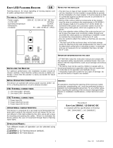
Description of parts
1
Transformer
2
Power LED
3
Display
4
Programming buttons
5
Trimmer to adjust the display lighting
6
Programming status warning LED
7
Memory Roll card connector
8
Connector for the R700 decoding card
9
Connector for plug-in radio frequency card (AF)
10
Terminal board for connecting the antenna
11
Terminal board for connecting the transponder selector
switch
12
Terminal board for connecting the limit switches
13
Terminal board for connecting control and safety devices
14
Terminal board for connecting the gearmotor
15
Terminal board for connecting the encoder
16
Power supply terminal board
17
Line fuse
18
Motor fuse
19
Electric-lock fuse
20
Control board fuse
21
Accessories fuse
22
RSE card connector
23
CRP connection terminal board
L N
E
+ -
E 10 11 TS E ES 1 2 3 4 5 CX CY CZ7 2
FA2 FC2FA1 FC1
+ -
M1 M2N1 N2
ENC1 ENC2
L2TL1T L2TL1T
24 12 0 24 12 0
B1 B2S1
GND
26
0V
17
0
230V
26
0V
17
0
230V
B
A
GND

p. 7 - Manual FA01315-EN - 01/2020 - © CAME S.p.A. - The contents of this manual may be changed, at any time, and without notice. - Original instructions
Size
295
320
215 240 145
120
Cable types and minimum thicknesses
Cable length (m) up to 20 from 20 to 30
Power supply 230 V AC 3G x 1.5 mm² 3G x 2.5 mm²
24 V AC/DC flashing beacon 2 x 0.5 mm² 2 x 0.5 mm²
TX Photocells 2 x 0.5 mm² 2 x 0.5 mm²
RX photocells 4 x 0.5 mm² 4 x 0.5 mm²
12 V DC electric lock 2 x 1 mm² 2 x 1.5 mm²
Command and control devices *no. x 0.5 mm² *no. x 0.5 mm²
* no. = see product assembly instructions - Warning: the cable cross-section is indicative and varies according to
the motor power and cable length.
When operating at 230 V and outdoors, use H05RN-F cables compliant with 60245 IEC 57 (IEC); when operating
indoors, use H05VV-F cables compliant with 60227 IEC 53 (IEC). For power supplies up to 48 V, you can use FROR
20-22 II cables compliant with EN 50267-2-1 (CEI).
To connect the antenna, use RG58 cable (up to 5 m).
To connect to the CRP, use a UTP CAT5 cable (up to 1,000 m long).
If the cable lengths dier from those specified in the table, define the cable cross-sections according to the
actual power draw of the connected devices and in line with regulation CEI EN 60204-1.
For multiple, sequential loads along the same line, recalculate the values in the table according to the actual
power draw and distances. For information on connecting products not covered in this manual, please see the
documentation accompanying the products themselves.
To connect the encoder, use a FROR 300/500 V shielded cable (3 x 0.5 mm2).

p. 8 - Manual FA01315-EN - 01/2020 - © CAME S.p.A. - The contents of this manual may be changed, at any time, and without notice. - Original instructions
INSTALLATION
Preparing the control panel
1
Separate the control-panel parts.
2
Assemble the pressure hinges.
3
Insert the hinges into the box (either on the left or the right) and fasten them using the screws and washers supplied. The
hinges slide to rotate.
4
Drill the pre-marked holes. The diameter of the holes is 20 mm.

p. 9 - Manual FA01315-EN - 01/2020 - © CAME S.p.A. - The contents of this manual may be changed, at any time, and without notice. - Original instructions
Fastening the control panel
1
Drill the fixing points of the control panel in a protected area.
2
Fasten the base using screws and plugs.
Use Phillips round head screws (maximum diameter 6 mm).
3
Insert the cable gland with the corrugated tubes for threading the electrical cables
295
215

p. 10 - Manual FA01315-EN - 01/2020 - © CAME S.p.A. - The contents of this manual may be changed, at any time, and without notice. - Original instructions
ELECTRICAL CONNECTIONS
Preparing the electrical cables
Connect all wires and cables in compliance with the law.
Use cable glands to connect the devices to the control panel. One of these must be used exclusively for the
power supply cable.
L N
E
+ -
E 10 11 TS E ES 1 2 3 4 5 CX CY CZ7 2
FA2 FC2FA1 FC1
+ -
M1 M2N1 N2
ENC1 ENC2
L2TL1T L2TL1T
24 12 0 24 12 0
B1 B2S1
GND
26
0V
17
0
230V
26
0V
17
0
230V
B
A
GND

p. 11 - Manual FA01315-EN - 01/2020 - © CAME S.p.A. - The contents of this manual may be changed, at any time, and without notice. - Original instructions
Power supply
1
Connecting to the mains (120/230 V AC - 50/60 Hz)
2
Power supply output for accessories
The output normally delivers 24 V AC.
The output delivers 24 V DC when the batteries start operating, if they are installed.
The sum of the power draw for the connected accessories must not exceed 50 W.
3
Connection for the 12 V AC electric lock - 15 W max.
L N
10 11 TS E ES 1 2 3 3P 4 5 7 CX CY CZ
Maximum capacity of contacts
Device Output Power supply (V) Power (W)
Accessories 10 - 11 24 AC/DC 50
Flashing beacon 10 - E 24 AC/DC 25
Operator status warning
light
10 - 5 24 AC/DC 3
Gearmotor without limit switch
1
Gearmotor delayed while opening
2
Gearmotor delayed while closing
M1 N1 E1
M2 N2 E2
N
M
M
N

p. 12 - Manual FA01315-EN - 01/2020 - © CAME S.p.A. - The contents of this manual may be changed, at any time, and without notice. - Original instructions
Gearmotor with limit switch
1
Gearmotor delayed while opening
2
Gearmotor delayed while closing
M1 N1 E1
M2 N2 E2
2 FA1 FC1 FA2 FC2
N
M
M
N
FC
FA
F
FA
FC
F
Gear motor with encoder
1
Gearmotor delayed while opening
2
Gearmotor delayed while closing
M1 N1 E1
M2 N2 E2
N
E
M
M
N
E
AMICO-AXO-FROG-J-MYTO-ATS
M1 N1 E1 + E -
M2 N2 E2 + E -
N
M
M
N
-
E
+
+
E
-
a
c
b
a
b
c
d
d
F4000-FAST-FERNI-FROG
a
Green cable
b
Brown cable
c
White cable
d
Earthing braid

p. 13 - Manual FA01315-EN - 01/2020 - © CAME S.p.A. - The contents of this manual may be changed, at any time, and without notice. - Original instructions
Command and control devices
1
STOP button (NC contact)
Stop the gate and exclude automatic closing. Use a control device to resume movement.
If the contact is not used, it must be deactivated during programming.
2
Control device (NO contact)
OPEN ONLY function
When the [HOLD-TO-RUN] function is active, the control device must be connected during OPENING.
3
Control device (NO contact)
PARTIAL OPENING function
4
Control device (NO contact)
CLOSE ONLY function
When the [HOLD-TO-RUN] function is active, the control device must be connected during CLOSING.
5
Control device (NO contact)
OPEN-CLOSE (step-by-step) or OPEN-STOP-CLOSE-STOP (sequential) function
See control function 2-7.
6
Card reader
7
Transponder selector switch
8
Antenna with RG58 cable
10 11 TS E ES 1 2 3 3P 4 5 7 CX CY CZ
S1 GND

p. 14 - Manual FA01315-EN - 01/2020 - © CAME S.p.A. - The contents of this manual may be changed, at any time, and without notice. - Original instructions
Signalling devices
1
Flashing beacon
It flashes when the operator opens and closes.
2
Additional light
It increases the light in the manoeuvring area.
3
Operator status warning light
It notifies the user of the operator status.
10 11 TS E ES 1 2 3 3P 4 5 7 CX CY CZ
Safety devices
During programming, configure the type of action that must be performed by the device connected to the input.
Connect the safety devices to the CX, CY and/or CZ inputs (NC contacts).
If contacts CX, CY and CZ are not used, they must be deactivated during programming.
DELTA photocells
Standard connection
DELTA photocells
Connection with safety test
See safety test function.
+
10
-
11 NO C NC
+
10
-
11
RX TX
10 11 ES TS 1 2 3 3P 4 5 7 CX CY CZ
10 11 TS E ES 1 2 3 3P 4 5 7 CX CY CZ
+
10
-
11 NO C NC
+
10
-
11
RX TX

p. 15 - Manual FA01315-EN - 01/2020 - © CAME S.p.A. - The contents of this manual may be changed, at any time, and without notice. - Original instructions
DIR / DELTA-S photocells
Standard connection
DIR / DELTA-S photocells
Connection with safety test
See safety test function.
10 11 TS E ES 1 2 3 3P 4 5 7 CX CY CZ
+
10
-
2 TX C NC TX 2
RX TX
10 11 TS E ES 1 2 3 3P 4 5 7 CX CY CZ
+
10
-
2 TX C NC TX 2
RX TX
DFWN sensitive edge
10 11 TS E ES 1 2 3 3P 4 5 7 CX CY CZ
C NO NC
DFWN

p. 16 - Manual FA01315-EN - 01/2020 - © CAME S.p.A. - The contents of this manual may be changed, at any time, and without notice. - Original instructions
PROGRAMMING
Programming button functions
1 2 3
1
ESC button
The ESC button is used to perform the operations described below.
Exit the menu
Delete the changes
Go back to the previous screen
2
< > buttons
The <> buttons are used to perform the operations described below.
Navigate the menu
Increase or decrease values
3
ENTER button
The ENTER button is used to perform the operations described below.
Access menus
Confirm a choice
Getting started
Once the electrical connections have been made, proceed with commissioning. Only skilled and qualified sta
may perform this operation.
Make sure that there are no obstacles in the way.
Power up and proceed with the operations indicated below.
Motor type
Number of motors
Total stop
Travel calibration
After powering up the system, the first manoeuvre is always to open the gate; Wait for the manoeuvre to be
completed.
Press the STOP button immediately in the event of any faults, malfunctions, strange noises or vibrations, or
unexpected behaviour in the system.
At the end of commissioning, check the correct operation of the device using the buttons near the display. Check that the
accessories also work correctly.
Functions menu
LANGUAGE
Choose the display language.
[LANGUAGE] [Italian] (Default)
[English]
[Français]
[Deutsch]
[Español]
[Português euro]
[Português bras]

p. 17 - Manual FA01315-EN - 01/2020 - © CAME S.p.A. - The contents of this manual may be changed, at any time, and without notice. - Original instructions
Automatic closure
Activate automatic closing.
[FUNCTIONS] [Automatic close] [Deactivated]
[Activated] (Default)
Hold-to-run
With the function active, the operator opening movement (command 2-3) or closing movement (command 2-4) is interrupted
when the control device is released.
When the function is active, it excludes all other control devices.
[FUNCTIONS] [Hold-to-run] [Deactivated] (Default)
[Activated]
[Closing]
Detecting obstacles
With the function active, the gate remains idle if the safety devices detect an obstacle. The function is active when the gate is
closed, open or after a complete stop.
[FUNCTIONS] [Obstruction det.] [Deactivated] (Default)
[Activated]
Safety devices test
Check that the photocells connected to the inputs are operating correctly, after each opening and closing command.
[FUNCTIONS] [Safety devices test] [Deactivated] (Default)
[CX]
[CY]
[CZ]
[CX+CY]
[CX+CZ]
[CY+CZ]
[CX+CY+CZ]
Pre-flashing
The flashing beacon is activated before each manoeuvre.
The pre-flashing duration is set with the [Pre-flashing T.] function
[FUNCTIONS] [Pre-flashing] [Deactivated] (Default)
[Activated]
Thrust
Before every opening or closing manoeuvre, the leaves thrust inwards to release the electric lock.
The thrust time is set with the [Thrust T.] function
[FUNCTIONS] [Thrust] [Deactivated] (Default)
[Close]
[Open]
[Open-Close]

p. 18 - Manual FA01315-EN - 01/2020 - © CAME S.p.A. - The contents of this manual may be changed, at any time, and without notice. - Original instructions
Total stop
Stop the gate and exclude automatic closing. Use a control device to resume movement.
[FUNCTIONS] [Total stop] [Deactivated]
[Activated] (Default)
CX input
Associate a function with the CX input.
[FUNCTIONS] [CX Input] [Deactivated]
[C1] = Reopen while closing
(Photocells) (Default)
[C2] = Reclose while opening
(Photocells)
[C3] = Partial stop Only with [Automatic
close] activated.
[C4] = Obstacle standby (Photocells)
[C7] = Reopen while closing (sensitive
edges)
[C8] = Reclose while opening (sensitive
edges)
CY input
Associate a function with the CY input.
[FUNCTIONS] [CY input] [Deactivated]
[C1] = Reopen while closing
(Photocells) (Default)
[C2] = Reclose while opening
(Photocells)
[C3] = Partial stop Only with [Automatic
close] activated.
[C4] = Obstacle standby (Photocells)
[C7] = Reopen while closing (sensitive
edges)
[C8] = Reclose while opening (sensitive
edges)

p. 19 - Manual FA01315-EN - 01/2020 - © CAME S.p.A. - The contents of this manual may be changed, at any time, and without notice. - Original instructions
CZ input
Associate a function with the CZ input.
[FUNCTIONS] [CZ input] [Deactivated]
[C1] = Reopen while closing
(Photocells) (Default)
[C2] = Reclose while opening
(Photocells)
[C3] = Partial stop Only with [Automatic
close] activated.
[C4] = Obstacle standby (Photocells)
[C7] = Reopen while closing (sensitive
edges)
[C8] = Reclose while opening (sensitive
edges)
Closing thrust
When the leaves reach the closing limit-switch, the operator performs a closing thrust for a few seconds.
[FUNCTIONS] [Cl. thrust] [Deactivated] (Default)
[Activated]
Lock
Associate the electric lock release with a command.
[FUNCTIONS] [Lock] [Deactivated] (Default)
[Close]
[Open]
[Open-Close]
Configurations
Configure slowdowns and limit switches.
[Slow.] and [Op.LS-Cl.Slow.] must be configured with the [Slow. T.].
[FUNCTIONS] [Config] [Slow.] = Slowdown during opening
and closing
[Op.LS-Cl.Slow.] = Opening limit-switch
and closing slowdown.
[ENCODER] = Encoder
[Time LS] = Time limit switch
[Limit switch] = Opening and closing
limit-switches
Limit switch
Configure the limit switch contacts as NO or NC.
[FUNCTIONS] [Limit switch] [N.C.] (Default)
[N.O.]

p. 20 - Manual FA01315-EN - 01/2020 - © CAME S.p.A. - The contents of this manual may be changed, at any time, and without notice. - Original instructions
Command 2-7
Associate a command with the device connected to 2-7.
[FUNCTIONS] [Command 2-7] [Open-Close](Default)
[Op. Stop Cl.]
Command 2-3P
Associate a command to the connected device on 2-3P.
[FUNCTIONS] [Command 2-3P] [Partial]
The degree of opening of the leaf
is set with the [Part. open] function
in the [SET TIME] menu.
[Pedestrian] (Default)
Additional light
Choose the operating mode of the lighting device connected to the output.
[FUNCTIONS] [Light E] [Flashing light] (Default)
[Courtesy]
The lamp stays on for 5 minutes.
[Cycle]
The lamp stays on during the
manoeuvre.
The light remains o if an
automatic closing time is not set.
B1-B2 output
Configure the contact.
[FUNCTIONS] [Output B1-B2] [Monostable] (Button)
[Bistable] (Switch)
CRP address
Set the peripheral number. The function is necessary if there are more operators in the same system.
[FUNCTIONS] [CRP address] from [1] to [32]
CRP Baud rate
Set the communication speed of the remote connection system.
[FUNCTIONS] [CRP Baud rate] [1200]
[2400]
[4800]
[9600]
[19200]
[38400] (Default)
[57600]
[115200]
/