Bard MULTI-TEC W42AAPA Installation Instructions Manual
- Type
- Installation Instructions Manual

INSTALLATION INSTRUCTIONS
MULTI-TEC
®
/th-TUNE
Free Cooling Unit System
th-Tune Single Unit Controller
NOTE: The th-Tune can be used as a replacement for the LC6000
controller for operation when a single W***AP* unit is used.
MULTI-TEC
®
Wall-Mount Air Conditioner
Models:
W18AAPA
W24AAPA
W24AAPB
W24AAPC
W30AAPA
W30AAPB
W30AAPC
W36AAPA
W36AAPB
W36AAPC
W42AAPA
W42AAPB
W42AAPC
W48AAPA
W48AAPB
W48AAPC
W48AAPQ
W60AAPA
W60AAPB
W60AAPC
W60AAPQ
W18LAPA
W24LAPA
W24LAPB
W30LAPA
W30LAPB
W30LAPC
W36LAPA
W36LAPB
W36LAPC
W42LAPA
W42LAPB
W42LAPC
W48LAPA
W48LAPB
W48LAPC
W48LAPQ
W60LAPA
W60LAPB
W60LAPC
W60LAPQ
W72LAPA
W72LAPB
W72LAPC
W72LAPQ
W72AAPA
W72AAPB
W72AAPC
W72AAPQ
Bard Manufacturing Company, Inc.
Bryan, Ohio 43506
www.bardhvac.com
Manual: 2100-678
Supersedes: NEW
Date: 9-20-17
Page 1 of 24

CONTENTS
General Information ...........................................3
List of Necessary Materials/Tools ....................5
Wall-Mount Unit Site Preparation ....................6
Model Identification .......................................... 6
New Shelter Installation vs. Retrofit Installation .. 6
Minimum Clearance .......................................... 6
Clearance to Combustibles ................................ 6
Wall-Mount Unit Installation ............................8
Mounting the Unit ............................................ 8
Wall-Mount Unit Supply Wiring ......................16
Main Power Wiring .......................................... 16
Low Voltage Wiring ......................................... 16
Wall-Mount Unit Preliminary Start Up ..........19
Running in Stand Alone (Orphan) Mode ............ 19
th-Tune Controller Installation ......................20
Mounting th-Tune Controller to Wall ................. 20
Power and Communication Wiring .................... 20
Power Wiring ........................................... 20
Communications Wiring ............................ 21
th-Tune Operation ........................................... 22
On/Off ..................................................... 22
Heat/Cool Operation ................................. 22
Auto Mode......................................... 22
Heat Mode ........................................ 22
Cool Mode ......................................... 22
Staging of Free Cooling and
Mechanical Cooling ............................ 22
Changing the Setpoint .............................. 22
Changing the Clock .................................. 23
Blower Operation ...................................... 23
th-Tune Setup Options Using the TEC-EYE . 23
Comfort Range ................................... 23
Alarms and Troubleshooting....................... 23
Alarms .............................................. 23
Troubleshooting ................................. 23
FIGURES AND TABLES
Figure 1 MULTI-TEC Model Nomenclature .............5
Figure 2 Dimensions ............................................7
Figure 3 Outdoor Sensor Installation
......................
8
Figure 4A W18A, W18L, W24A, W24L
Mounting Instructions
..............................
9
Figure 4B W30A, W30L, W36A, W36L
Mounting Instructions
............................
10
Figure 4C W42A, W42L, W48A, W48L
Mounting Instructions
............................
11
Figure 4D W60A, W60L, W72A, W72L
Mounting Instructions
............................
12
Figure 5 Electric Heat Clearance ......................... 13
Figure 6 Wall Mounting Instructions ....................13
Figure 7 Wall Mounting Instructions ....................14
Figure 8 Common Wall Mounting Installations ......15
Figure 9 Circuit Routing Label ............................16
Figure 10 WIRING: VAC Supply Wiring
Landing Points .....................................16
Figure 15 th-Tune Power and Communication
Connections .........................................21
Figure 16 Wall Unit and th-Tune Power and
Communications Connections ................21
Figure 17 Proper Communication Connector
Placement ...........................................21
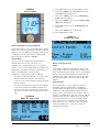
Figure 18 Change Setpoint ...................................22
Figure 19 Comfort Range .....................................22
Figure 20 MULTI-TEC Status Screen .....................23
Figure 21 Comfort Range Setup ............................23
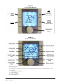
Figure 22 th-Tune Buttons Overview ......................24
Figure 23 th-Tune Icons Overview .........................24
Table 1 Electrical Specifications –
W**AAP Series ..................................... 17
Table 2 Electrical Specifications –
W**LAP Series .....................................18
Manual 2100-678
Page 2 of 24

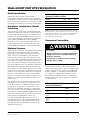
GENERAL INFORMATION
Free Cooling Unit System
This Bard Free Cooling Unit System is composed of
MULTI-TEC wall-mounted air conditioners matched
with an LC6000 lead/lag controller or Bard th-Tune
single unit controller. If only one wall-mounted air
conditioner is being used, it can be matched with
either the LC6000 lead/lag controller or a th-Tune
single unit controller. If more than one wall mount
is installed, the LC6000 lead/lag controller must be
matched with the air conditioning units. The wall
mounts are specifically engineered for telecom/motor
control center rooms.
NOTE: The LC6000 lead/lag controller (or th-Tune
single unit controller) and MULTI-TEC wall-
mount units are designed specifically to work
together. These controllers cannot run other
Bard models or other brands of systems, nor
can other controllers run the MULTI-TEC wall-
mount units. They are a complete system, and
must be used together.
Wall-Mount Air Conditioner Units
The
MULTI-TEC
units operate on VAC power.
The
units will supply 100% of rated cooling airflow in free
cooling mode with ability to exhaust the same amount
through the unit itself without any additional relief
openings in the shelter.
Each of these units are fully charged with refrigerant
and may have optional auxiliary heat.
Controller
A th-Tune single unit controller (Bard P/N 8403-
088) can be used in place of the LC6000 controller
when only one MULTI-TEC wall-mount air conditioner
is being controlled. If using a th-Tune stand-alone
controller instead of the LC6000 controller, the alarm
logging and remote communication capabilities of
the LC6000 controller will not be available. A TEC-
EYE
TM
hand-held diagnostic tool is required to program
the wall-mount unit for th-Tune single unit controller
operation. The th-Tune controller and TEC-EYE
diagnostic tool are available as a kit (Bard P/N 8620-
264).
General
The equipment covered in this manual is to be installed
by trained, experienced service and installation
technicians.
The refrigerant system is completely assembled and
charged. All internal wiring is complete.
The unit is designed for use with or without duct work.
Flanges are provided for attaching the supply and return
ducts.
These instructions explain the recommended method
to install the air cooled self-contained unit and the
electrical wiring connections to the unit.
These instructions and any instructions packaged with
any separate equipment required to make up the entire
air conditioning system should be carefully read before
beginning the installation. Note particularly any tags
and/or labels attached to the equipment.
While these instructions are intended as a general
recommended guide, they do not supersede any national
and/or local codes in any way. Authorities having
jurisdiction should be consulted before the installation
is made. See Additional Publications below for
information on codes and standards.
Sizing of systems for proposed installation should be
based on heat loss and heat gain calculations made
according to methods of Air Conditioning Contractors of
America (ACCA). The supply flange should be installed
in accordance with the Standards of the National
Fire Protection Association for the Installation of Air
Conditioning and Ventilating Systems of Other Than
Residence Type, NFPA No. 90A, and Residence Type
Warm Air Heating and Air Conditioning Systems, NFPA
No. 90B. Where local regulations are at a variance with
instructions, installer should adhere to local codes.
Shipping Damage
Upon receipt of equipment, the cartons should be
checked for external signs of shipping damage. If
damage is found, the receiving party must contact
the last carrier immediately, preferably in writing,
requesting inspection by the carrier’s agent.
These units must remain in upright position at all
times.
Additional Publications
These publications can help when installing the
furnace. They can usually be found at the local library
or purchased directly from the publisher. Be sure to
consult the current edition of each standard.
National Electrical Code ......................ANSI/NFPA 70
Standard for the Installation of Air Conditioning
and Ventilating Systems ...................ANSI/NFPA 90A
Standard for Warm Air Heating
and Air Conditioning Systems ............ANSI/NFPA 90B
Load Calculation for Residential Winter
and Summer Air Conditioning ............. ACCA Manual J
For more information, contact these publishers:
Air Conditioning Contractors of America (ACCA)
1712 New Hampshire Ave. N.W.
Washington, DC 20009
Telephone: (202) 483-9370 Fax: (202) 234-4721
Manual 2100-678
Page 3 of 24

American National Standards Institute (ANSI)
11 West Street, 13th Floor
New York, NY 10036
Telephone: (212) 642-4900 Fax: (212) 302-1286
American Society of Heating, Refrigeration and Air
Conditioning Engineers, Inc. (ASHRAE)
1791 Tullie Circle, N.E.
Atlanta, GA 30329-2305
Telephone: (404) 636-8400 Fax: (404) 321-5478
National Fire Protection Association (NFPA)
Batterymarch Park
P. O. Box 9101
Quincy, MA 02269-9901
Telephone: (800) 344-3555 Fax: (617) 984-7057
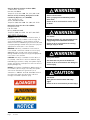
ANSI Z535.5 Definitions:
DANGER: Indicate[s] a hazardous situation which, if
not avoided, will result in death or serious injury. The
signal word “DANGER” is to be limited to the most
extreme situations. DANGER [signs] should not be used
for property damage hazards unless personal injury risk
appropriate to these levels is also involved.
WARNING: Indicate[s] a hazardous situation which,
if not avoided, could result in death or serious injury.
WARNING [signs] should not be used for property
damage hazards unless personal injury risk appropriate
to this level is also involved.
CAUTION: Indicate[s] a hazardous situation which, if
not avoided, could result in minor or moderate injury.
CAUTION [signs] without a safety alert symbol may be
used to alert against unsafe practices that can result in
property damage only.
NOTICE: [this header is] preferred to address practices
not related to personal injury. The safety alert symbol
shall not be used with this signal word. As an
alternative to “NOTICE” the word “CAUTION” without
the safety alert symbol may be used to indicate a
message not related to personal injury.
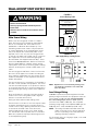
!
WARNING
Electric shock hazard.
Have a properly trained individual perform
these tasks.
Failure to do so could result in electric shock
or death.
!
WARNING
Fire hazard.
Maintain minimum 1/4" clearance between the
supply ange and combustible materials.
Failure to do so could result in re causing
damage, injury or death.
!
CAUTION
Cut hazard.
Wear gloves to avoid contact with sharp
edges.
Failure to do so could result in personal injury.
!
WARNING
Heavy item hazard.
Use more than one person to handle unit.
Failure to do so could result in unit damage or
serious injury.
Manual 2100-678
Page 4 of 24

LIST OF NECESSARY MATERIALS/TOOLS
Additional hardware and miscellaneous supplies are needed for installation. These items are field supplied and must
be sourced before installation. This list also includes tools needed for installation.
LIST OF MATERIALS/TOOLS
• Personal protective equipment/safety devices/anti-
static wrist straps
• Supply and return grilles
• Field-fabricated sleeves (if necessary)
• Fasteners sufficient for mounting the units such as
5/16” diameter anchor/lag bolts
• 7/8” diameter washers
• Fasteners appropriate for the shelter wall
construction to attach the controller to the wall
• Commercial grade outdoor silicone sealant
• Miscellaneous hand and power tools and jobsite or
shop materials
• Lifting equipment with the necessary capacity and
rigging to safely move/install the systems
• Electrical supplies
- Various size circuit breakers for the shelter AC
breaker box (see Tables 1 and 2 on pages 17
and 18)
- High-voltage wire of various gauges
(see Tables 1 and 2)
- Communication wire: 3-wire, 20 gauge
shielded cable
- Miscellaneous electrical supplies including
rigid/flexible conduit and fittings, junction
boxes, wire connectors and supports
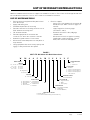
FIGURE 1
MULTI-TEC Wall-Mount Unit Model Nomenclature
CONTROL MODULES
E – LAC
C – LAC & CCH
COIL OPTIONS
X – Standard
1 – Phenolic Coated Evaporator
2 – Phenolic Coated Condenser
3 – Phenolic Coated Evaporator
and Condenser
P – PLC Logic Board
W 36 A A P A 10 5 X X X X E
MODEL SERIES
REVISION
KW
A – Right Hand
L – Left Hand
FILTER OPTIONS
X – 1" Throwaway (Standard)
W – 1" Washable
P – 2" Pleated (MERV 8)
SUPPLY AIR OUTLET
X – Front (Standard)
COLOR OPTIONS
X – Beige (Standard)
1 – White
4 – Buckeye Gray
18 – 1½ Ton
24 – 2 Ton
30 – 2½ Ton
36 – 3 Ton
CAPACITY
42 – 3½ Ton
48 – 4 Ton
60 – 5 Ton
72 – 6 Ton
VENTILATION OPTIONS
B – Blank-off Plate
5 – Economizer: Default Enthalpy Convert to DB Only
A – 230/208/60/1
B – 230/208/60/3
C – 460/60/3
D – 240/220/50/1
VOLTS & PHASE
E – 240/220/50/3
or 220/200/50/3
F – 415/380/50/3
Q – 575/60/3
Manual 2100-678
Page 5 of 24

WALL-MOUNT UNIT SITE PREPARATION
Model Identification
Identify the specific model using the model
nomenclature information found in Figure 1 and the
model/serial tag found on the unit on the opposite side
of the control and access panels. See Figure 2 on page
8 for dimensions and critical installation requirements.
New Shelter Installation vs. Retrofit
Installation
These installation instructions cover both new shelter
installations and retrofit installations. Each installation
is unique and may require special accomodations and
modifications. Although Bard Manufacturing follows a
long-established tradition of manufacturing equipment
using industry standard dimensions for building
penetration, it is occasionally necessary to move or
enlarge supply and return openings when replacing
non-standardized equipment in a retrofit application.
Minimum Clearance
Wall-mount air conditioners are available in both right-
hand access models and left-hand access models.
Right-hand access models have the heat strip access
panel, external circuit breakers access panel and
internal controls access panel on the right side of the
unit. Left-hand access models are a mirror image of the
right-hand access models, and allow two wall-mount
units to be placed in relatively close proximity and yet
still allow complete access for maintenance and repair.
On side-by-side installations, maintain a minimum of
20" clearance on control side to allow access to control
panel and heat strips, and to allow proper airflow to the
outdoor coil. For installations where units are installed
with both control panels facing each other (inward),
maintain a minimum of 36" clearance to allow access.
Additional clearance may be required to meet local or
national codes.
Care should be taken to ensure that the recirculation
and obstruction of condenser discharge air does not
occur. Recirculation of condenser discharge air can
be from either a single unit or multiple units. Any
object such as shrubbery, a building or a large object
can cause obstructions to the condenser discharge air.
Recirculation or reduced airflow caused by obstructions
will result in reduced capacity, possible unit pressure
safety lockouts and reduced unit service life.
For units with blow through condensers, such as
these wall-mount units, it is recommended there be
a minimum distance of 10' between the front of the
unit and any barrier or 20' between the fronts of two
opposing (facing) units.
The unit itself is suitable for 0" clearance, but the
supply air duct flange and the first 3' of supply air duct
require a minimum of 1/4" clearance to combustible
material. However, it is generally recommended that
a 1" clearance is used for ease of installation and
maintaining the required clearance to combustible
material. See Figures 4A-D on pages 9-12 for details
on opening sizes.
Clearance to Combustibles
NOTE: For side-by-side installation of two units there must be
20" between units. This can be reduced to 15" by using a W**L
model (left side compressor and controls) for the left unit and
W**A (right side compressor and controls) for right unit.
See Specifications Sheet S3532.
Minimum Clearances Required to
Combustible Materials
MODELS
SUPPLY AIR DUCT
FIRST 3'
CABINET
W18A, L
W24A, L
0" 0"
W30A, L
W36A, L
1/4" 0"
W42A, L
W48A, L
W60A, L
W72A, L
1/4" 0"
Clearances Required for Service Access and
Adequate Condenser Airflow
MODELS
LEFT
SIDE
RIGHT
SIDE
DISCHARGE
SIDE
W18A, W24A, W30A, W36A 15" 20" 10'
W18L, W24L, W30L, W36L 20" 15" 10'
W42A, W48A, W60A, W72A 20" 20" 10'
W42L, W48L, W60L, W72L 20" 20" 10'
!
WARNING
Fire hazard.
Maintain minimum 1/4" clearance between the
supply air duct and combustible materials in
the rst 3' of ducting.
Failure to do so could result in re causing
damage, injury or death.
Manual 2100-678
Page 6 of 24

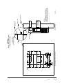
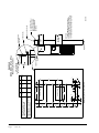
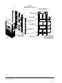
FIGURE 2
Dimensions of Basic Unit for Architectural and Installation Requirements (Nominal)
MODEL
WIDTH
(W)
DEPTH
(D)
HEIGHT
(H)
SUPPLY RETURN
A B C B E F G I J K L M N O P Q R S T
W18*A
W24*A
33.300 17.125 74.563 7.88 19.88 11.88 19.88 35.00 10.88 29.75 20.56 30.75 32.06 33.25 31.00 2.63 34.13 26.06 10.55 4.19 12.00 9.00
W30*A
W36*A
38.200 17.125 74.563 7.88 27.88 13.88 27.88 40.00 10.88 29.75 17.93 30.75 32.75 33.25 31.00 2.75 39.13 26.75 9.14 4.19 12.00 9.00
W42*A
W48*A
42.075 22.432 84.875 9.88 29.88 15.88 29.88 43.88 13.56 31.66 30.00 32.68 26.94 34.69 32.43 3.37 43.00 23.88 10.00 1.44 16.00 1.88
W60*A
W72*A
42.075 22.432 93.000 9.88 29.88 15.88 29.88 43.88 13.56 37.00 30.00 40.81 35.06 42.81 40.56 3.37 43.00 31.00 10.00 1.44 16.00 10.00
All dimensions are in inches. Dimensional drawings are not to scale.
W**A
RIGHT
UNIT
W**L
LEFT
UNIT
Ventilation Air
Condenser
Front View
Filter Access Panel
Air Outlet
Standard
flush vent
door for non-
ERV/CRV
Econ.
models
1
F
G
W
5.88
Electric
Heat
MIS-3889
Electrical
Entrances
Optional
Supply Air Opening
Side Wall
Mounting
(Built In)
Shipping
Location
Brackets
Return Air Opening
Top Rain
Flashing
Bottom Installation
Bracket
Back View
B
P
M
O
E
R
S
S
S
S
S
T
.44
N
Q
L
Low Voltage
Electrical
Entrance
Rain Hood
Entrance
Disconnect
4° Pitch
Built In
Heater
Cond.
Access Panel
(Lockable)
Inlet
Air
Panel
Access
C. Breaker/
High Voltage
Electrical
Drain
Side View
1.250
2.13
I
D
J
C
H
A
K
7.00
Hood for ECON
models only
MIS-3889
1.250
I
A
C
K
2.13
H
J
N
Q
P
M
L
O
E
.44
W
5.88
F
G
R
S
S
S
S
S
T
D
B
1
Drain
Air
Entrance
Filter Access Panel
Heat
High Voltage
Front View
Air Outlet
Supply Air Opening
Return Air Opening
Disconnect
Electric
Inlet
Side View
Top Rain
Cond.
Electrical
Back View
Condenser
Bracket
Installation
Bottom
Brackets
Mounting
Side Wall
Location
Shipping
Flashing
Entrances
Electrical
Optional
Econ. models
(Built In)
Heater
Access
Panel
Ventilation Air
Entrance
Electrical
vent door for
Standard flush
Low Voltage
non-ERV/CRV
(Lockable)
Access Panel
C. Breaker/
Built In
Rain Hood
4° Pitch
MIS-3890
7.000
Hood for
ECON models
only
MIS-3890
Manual 2100-678
Page 7 of 24

6. Position unit in opening and secure with fasteners
sufficient for the application such as 5/16" lag/
anchor/carriage bolts; use 7/8" diameter flat washers
on the lag bolts. It is recommended that a bead
of silicone caulking be placed behind the side
mounting flanges.
7. Secure optional rain flashing to wall and caulk
across entire length of top (see Figures 4A-D).
8. For additional mounting rigidity, the return air
and supply air frames or collars can be drilled
and screwed or welded to the structural wall itself
(depending upon wall construction). Be sure to
observe required clearance if combustible wall.
9. A plastic drain hose extends from the drain pan at
the top of the unit down to the unit base. There are
openings in the unit base for the drain hose to pass
through. In the event the drain hose is connected
to a drain system of some type, it must be an open
or vented type system to assure proper drainage.
10. Install outdoor temperature/humidity sensor (see
Figure 3). Remove grommet from base and sensor.
Discard shipping bracket. Place sensor extension
through hole in base under condenser fan and
secure to base with screw.
Mounting the Units
NOTE: It may be best to spot some electrical knockouts
(such as those located on the back of the wall-
mount unit) before units are mounted and access is
unavailable or limited (see Figure 2 to locate pre-
punched knockouts).
Two holes for the supply and return air openings must
be cut through the wall as shown in Figures 4A-D on
pages 9-12. On wood frame walls, the wall construction
must be strong and rigid enough to carry the weight
of the unit without transmitting any unit vibration. All
walls must be thoroughly inspected to insure that they
are capable of carrying the weight of the installed unit.
In retrofit (unit replacement) installations, the openings
cut for the original equipment may not line up exactly
with needs of this installation. Modifications may need
to be made, such as increasing or decreasing the size
of the wall cutouts. The existing bolt placement may
not line up in which case the original bolts would need
to be removed or cut away.
1. These units are secured by wall mounting flanges
which secure the unit to the outside wall surface at
both sides. A bottom mounting bracket, attached
to skid for shipping, is provided for ease of
installation, but is not required.
2. The unit itself is suitable for 0" clearance, but the
supply air duct flange and the first 3' of supply
air duct require a minimum of 1/4" clearance to
combustible material. However, it is generally
recommended that a 1" clearance is used for
ease of installation and maintaining the required
clearance to combustible material. See Figures
4A-D for details on opening sizes.
3. Locate and mark lag bolt locations and location for
optional bottom mounting bracket, if desired (see
Figures 4A-D).
4. Mount bottom mounting bracket (if used).
5. If desired, hook top rain flashing (attached to front-
right of supply flange for shipping) under back
bend of top.
WALL-MOUNT UNIT INSTALLATION
FIGURE 3
Outdoor Sensor Installation
!
WARNING
Heavy item hazard.
Use more than one person to handle unit.
Failure to do so could result in unit damage or
serious injury.
Manual 2100-678
Page 8 of 24

FIGURE 4A
W18A, W18L, W24A, W24L
Mounting Instructions
12"
12"
12"
12"
12"
20"
20"
8"
20
1
2
"
12"
3
13
16
"
2"
2"
7
1
16
" 7
1
16
"
5"
1"
3"
4"
Typ.
3
1
8
"
4"
Typ.
7
8
"
9"
NOTES:
WALL STRUCTURE
ENTIRE LENGTH OF TOP.
TOP
WALL
OF CAULKING ALONG
PANEL
FOAM AIR SEAL
DUCT
RAIN FLASHING
HEATER ACCESS
MIS-3157 A
Wall Opening and Hole Location View Right Side View
RETURN AIR
TOP FLASHING AT TIME OF INSTALLATION.
OPENING
THE SIDE MOUNTING FLANGES AND UNDER
SEAL WITH BEAD
IT IS RECOMMENDED THAT A BEAD OF
SILICONE CAULKING BE PLACED BEHIND
SUPPLY AIR
SUPPLIED
Return Opening
Supply Opening
J**A UNIT SHOWN, J**L UNIT
CONTROLS AND HEATER ACCESS
IS ON OPPOSITE (LEFT) SIDE.
Manual 2100-678
Page 9 of 24

FIGURE 4B
W30A, W30L, W36A, W36L
Mounting Instructions
2
C
D
C
12"
12"
12"
12"
12"
B
28"
14"
4
11
16
"
4
11
16
"
4"
Typ.
"
1
8
A
7
8
"
7
8
"
4"
Typ.
3
7
8
"
E
9
1
16
"
4
7
8
"
RETURN AIR
SILICONE CAULKING BE PLACED BEHIND
SUPPLIED
NOTES:
ENTIRE LENGTH OF TOP.
THE SIDE MOUNTING FLANGES AND UNDER
1/4" CLEARANCE ON ALL
DUCT
OF CAULKING ALONG
PANEL
FOAM AIR SEAL
WALL STRUCTURE
FOUR SIDES OF SUPPLY
AIR DUCT IS REQUIRED
FROM COMBUSTABLE
MATERIALS
RAIN FLASHING
TOP
SUPPLY AIR
OPENING
Right Side View
HEATER ACCESS
TOP FLASHING AT TIME OF INSTALLATION.
SEAL WITH BEAD
IT IS RECOMMENDED THAT A BEAD OF
WALL
Wall Opening and Hole Location View
17 5/8
4 5/8 16 7/8
8 3/8
A
9 7/829 7/8
Return Opening
4 7/16
3 11/16
1/4" MIN. CLEARANCE FROM
28 3/8
ED
5 3/8
B
COMBUSTIBLE MATERIALS
C
RECOMMENDED 1" CLEARANCE FROM
REQUIRED DIMENSIONS TO MAINTAIN
COMBUSTIBLE MATERIALS
REQUIRED DIMENSIONS TO MAINTAIN
Supply Opening
W**A UNIT SHOWN, W**L UNIT
CONTROLS AND HEATER ACCESS
IS ON OPPOSITE (LEFT) SIDE.
MIS-3820
Manual 2100-678
Page 10 of 24

FIGURE 4C
W42A, W42L, W48A, W48L
Mounting Instructions
D
16"
16"
16"
16"
16"
1
7
8
"
6
1
2
" 6
1
2
"
2
1
8
"
7
8
"
1"
3"
4"
Typ.
4"
Typ.
6
1
2
"
30"
E
16"
A CC
3
1
8
"
B
Wall Opening and Hole Location View
RETURN AIR
1
REQUIRED DIMENSIONS TO MAINTAIN
1/4" MIN. CLEARANCE FROM
COMBUSTIBLE MATERIALS
REQUIRED DIMENSIONS TO MAINTAIN
29
DUCT
COMBUSTIBLE MATERIALS
A B C DE
30 1/2
10 1/2
6 1/4 1 1/4 29 3/4
32 12 5 1/2
2
NOTES:
WALL STRUCTURE
1
SUPPLY AIR
IT IS RECOMMENDED THAT A BEAD OF
OPENING
Right Side View
RAIN FLASHING
SILICONE CAULKING BE PLACED BEHIND
RECOMMENDED 1" CLEARANCE FROM
THE SIDE MOUNTING FLANGES AND UNDER
TOP FLASHING AT TIME OF INSTALLATION.
TOP.
PANEL
HEATER ACCESS
FOUR SIDES OF SUPPLY
AIR DUCT IS REQUIRED
FROM COMBUSTABLE
WALL
1/4" CLEARANCE ON ALL
MATERIALS
Supply Opening
FOAM AIR SEAL
SUPPLIED
SEAL WITH BEAD
OF CAULKING ALONG
ENTIRE LENGTH OF
TOP
1
Return Opening
MIS-416 E
Dimension is 21" on 95" tall units.
2
Dimension is 10" on T48H1 & T60H1.
2
Dimension is 6" on T48H1 & T60H1.
3
3
Manual 2100-678
Page 11 of 24

FIGURE 4D
W60A, W60L, W72A, W72L
Mounting Instructions
D
16"
16"
16"
16"
16"
2
"6
8
" 5
8
9
7
"
1"
3"
Typ.
1
4"
4"
Typ.
6
1
2
"
30"
E
16"
A CC
"
7
8
3
B
"
8
7
1
1
2
"6
1 1/430 1/2
1/4" CLEARANCE ON ALL
SUPPLIED
FOAM AIR SEAL
A
Supply Opening
SILICONE CAULKING BE PLACED BEHIND
DUCT
FOUR SIDES OF SUPPLY
FROM COMBUSTABLE
1/4" MIN. CLEARANCE FROM
COMBUSTIBLE MATERIALS
REQUIRED DIMENSIONS TO MAINTAIN
OPENING
COMBUSTIBLE MATERIALS
B D E
PANEL
AIR DUCT IS REQUIRED
32
10 1/2
Right Side View
SUPPLY AIR
RECOMMENDED 1" CLEARANCE FROM
MIS-3789
RAIN FLASHING
REQUIRED DIMENSIONS TO MAINTAIN
12
TOP.
MATERIALS
5 1/2
WALL STRUCTURE
2
6 1/4
29
29 3/4
IT IS RECOMMENDED THAT A BEAD OF
THE SIDE MOUNTING FLANGES AND UNDER
WALL
C
Wall Opening and Hole Location View
NOTES:
TOP FLASHING AT TIME OF INSTALLATION.
HEATER ACCESS
RETURN AIR
SEAL WITH BEAD
OF CAULKING ALONG
ENTIRE LENGTH OF
TOP
Return Opening
Manual 2100-678
Page 12 of 24

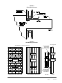
FIGURE 5
Electric Heat Clearance
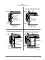
FIGURE 6
Wall Mounting Instructions
DUCT
OPENING
RETURN AIR
SUPPLY AIR
WOOD FRAME WALL INSTALLATION
OPENING
WALL BEFORE
MOUNT ON UNIT
OPENING
BEFORE INSTALLATION
BOTTOM MOUNTING
CONCRETE BLOCK WALL INSTALLATION
BRACKET. MOUNT ON
OPENING
WOOD OR STEEL SIDING
OPENING
INSTALLING UNIT.
RETURN AIR
WALL STRUCTURE
RETURN AIR
SUPPLY AIR
FACTORY SUPPLIED
RAIN FLASHING.
SUPPLY AIR
MIS-548 A
SIDE VIEW
See FIGURE 2 – Mounting Instructions
Manual 2100-678
Page 13 of 24

FIGURE 7
Wall Mounting Instructions
I
A
C
K
E + 1.000
B
1.000
SUPPLY DUCT
OVER FRAME
INTERIOR FINISHED WALL
ALL AROUND DUCT
FRAMING MATERIAL
EXTERIOR FINISH WALL
OPENING
FOR ACTUAL DIMENSIONS.
2 x 4'S, 2 x 6'S &/OR
STRUCTURAL STEEL
ATTACH TO TOP
1.000" CLEARANCE
1.000" CLEARANCE
PLATE OF WALL
C
SEE UNIT DIMENSIONS, FIGURE 1.2,
OPENING
RETURN DUCT
2 x 6
ATTACH TO BOTTOM
OVER FRAME
PLATE OF WALL
L
THIS STRUCTURAL MEMBER
LOCATED TO MATCH STUD
SPACING FOR REST OF WALL.
A SECOND MEMBER MAY BE
REQUIRED FOR SOME WALLS.
MIS-549 B
ALL AROUND DUCT
Manual 2100-678
Page 14 of 24

FIGURE 8
Common Wall Mounting Installations
RAFTERS
RAFTERS
RAFTERS
RAFTERS
FALSE WALL
OUTSIDE
WALL
NO DUCT
SUPPLY AIR
GRILLE
DUCTED SUPPLY
RETURN AT UNIT
WALL
RAISED FLOOR
RETURN AIR
LOWERED
GRILLE
RETURN AIR
WALL
CEILING SURFACE
SPACE
RETURN AI R
RETURN AIR GRILLE
WALL
OUTSIDE
SUPPLY AIR DUCT
SUPPLY AIR DUCT
SUPPLY AIR DUCT
RETURN AIR
OPENING W/ GRILLE
OUTSIDE
FALSE WALL INSTALLATION
CEILING
RAIN
FLASHING
RAIN
FLASHING
SUPPLY DUCT MAY BE LOCATED IN AN ATTIC
OR BELOW CEILING RAFTERS AS SHOWN
FINISHED CEILING
WALL
CLOSET WALL
SURFACE
SLEEVE
SUPPLY DUCT MAY BE LOCATED IN AN ATTIC OR
BELOW CEILING RAFTERS AS SHOWN
OUTSIDE
WALL SLEEVE
SUPPLY DUCT MAY BE LOCATED IN AN ATTIC
OR BELOW CEILING RAFTERS AS SHOWN
FINISHED CEILING SURFACE
RAIN
FLASHING
RAIN
FLASHING
CLOSET INSTALLATION
FINISHED
MIS-550 C
FREE AIR FLOW
FINISHED CEILING SURFACE
SUPPLY AIR DUCT
W/GRILLE
WALL SLEEVE
RETURN AIR
OPENING W/GRILLE
WALL SLEEVE
WALL SLEEVE
Manual 2100-678
Page 15 of 24

WALL-MOUNT UNIT SUPPLY WIRING
Main Power Wiring
Refer to the unit rating plate or Table 1 or Table 2
(page 18) for wire sizing information and maximum
fuse or circuit breaker size. Each outdoor unit is
marked with a “Minimum Circuit Ampacity”. The
field wiring used must be sized to carry that amount
of current. Depending on the installed KW of electric
heat, there may be two or three field power circuits
required. If this is the case, the unit rating plate will
so indicate. All models are suitable only for connection
with copper wire. Each unit and/or wiring diagram
will be marked “Use Copper Conductors Only”. These
instructions must be adhered to. Refer to the National
Electrical Code (NEC) for complete current carrying
capacity data on the various insulation grades of wiring
material. All wiring must conform to NEC and all local
codes.
The unit rating plate and Tables 1 and 2 list fuse and
wire sizes (75°C copper) for all models including the
most commonly used heater sizes. Also shown are the
number of field power circuits required for the various
models with heaters.
The unit rating plate lists a maximum circuit breaker or
fuse that is to be used with the equipment. The correct
size must be used for proper circuit protection and also
to assure that there will be no nuisance tripping due to
the momentary high starting current of the compressor
motor.
Route all field wires to the right of the wire shield as
shown in the circuit routing label found in Figure 9
(and also on the wall-mount units).
See Figure 10 to reference VAC landing points.
The disconnect access door on this unit may be locked
to prevent unauthorized access to the disconnect. To
convert for the locking capability, bend the tab located
in the bottom left-hand corner of the disconnect
opening under the disconnect access panel straight
out. This tab will now line up with the slot in the door.
When shut, a padlock may be placed through the hole
in the tab preventing entry.
FIGURE 9
Circuit Routing Label
FIGURE 10
VAC Supply Wiring Landing Points
NOTE: Right-hand access model wiring landing points
are shown here; left-hand access models will
mirror this image.
Field
Wiring
Factory
Wiring
2.500
5.000
REV. DATE DESCRIPTION ECN NO DRN CHK APR
A 3/17/2014 ADDED FRENCH VERSION 11182 BD SD RP
A
WIRING ROUTING LABEL
7961-393
1:4
3/17/2014
DAY
SD RP
NOTICE / AVIS
ROUTE ALL HIGH VOLTAGE FIELD
WIRES TO THE RIGHT OF THE WIRE
SHIELD AS SHOWN
ACHEMINER LES FILS HAUTE
TENSION SUR LA DROITE VERS LA
PROTECTION, COMME INDIQUÉ
CIRCUIT BREAKER
/DISJONCTEUR
WIRE SHIELD /
PROTECTION
COMPRESSOR
CONTACTOR /
CONTACTEUR DU
COMPRESSEUR
MATERIAL : OUTDOOR VINYL
BACKGROUND COLOR : WHITE / SAFETY BLUE
PRINTING COLOR : BLACK 1/8" LETTERING
SIZE : 2.500 X 5.000
FORMAT : ROLL
7961-393
WHITE 3/16" LETTERING
7961-393
A
RP
3/17/2014
DRAWN BYSCALE
DISTRIBUTION
DWG.
CHECKED APPROVED
NO. NO.
DATE
PART
NAME
MAT'L
Bard Mfg. Co.
Bryan, Ohio
PART
1 2 3 4 5
Low Voltage Wiring
230/208V 1 phase and 3 phase equipment use dual
primary voltage transformers. All equipment leaves the
factory wired on 240V tap. It is very important that
the correct voltage tap is used. For 208V operation,
reconnect from 240V to 208V tap. The acceptable
operating voltage range for the 240 and 208V taps are:
240V Tap (253 – 216) and 208 Tap (220 – 197).
NOTE: The voltage should be measured at the field
power connection point in the unit and while
the unit is operating at full load (maximum
amperage operating condition.
For low voltage wiring, an 18 gauge copper, color-coded
cable is recommended.
!
WARNING
Electric shock hazard.
Have a properly trained individual perform
these tasks.
Failure to do so could result in electric shock
or death.
Manual 2100-678
Page 16 of 24

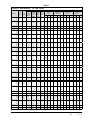
TABLE 1
Electrical Specifications – W**AAP Series
MODEL
Rated
Volts
&
Phase
No. Field
Power
Circuits
Single Circuit Multiple Circuit
Minimum
Circuit
Ampacity
Maximum
External
Fuse or
Ckt. Brkr.
Field
Power
Wire
Size
Ground
Wire
Minimum
Circuit
Ampacity
Maximum
External Fuse or
Ckt. Breaker
Field Power
Wire Size
Ground
Wire Size
Ckt. A Ckt. B Ckt. C Ckt. A Ckt. B Ckt. C Ckt. A Ckt. B Ckt. C Ckt. A Ckt. B Ckt. C
W18AAPA00, A0Z
A05
A08
A10
230/208-1
1
1
1
1
16
30
46
56
20
30
50
60
12
10
8
6
12
10
10
10
W24AAPA00, A0Z
A04
A05
A08
A10
230/208-1
1
1
1
1
1
21
25
30
46
56
30
30
30
50
60
10
10
10
8
6
10
10
10
10
10
W24AAPB00, B0Z
B06
230/208-3
1
1
15
22
20
25
12
10
12
10
W24AAPC00, C0Z
C06
460-3
1
1
9
11
15
15
14
14
14
14
W30AAPA00, A0Z
A05
A08
A10
A15
230/208-1
1
1
1
1
1 or 2
26
32
47
58
84
35
35
50
60
90
8
8
8
6
4
10
10
10
10
8 58 26 60 30 6 10 10 10
W30AAPB00, B0Z
B06
B09
B15
230/208-3
1
1
1
1
19
24
33
51
20
25
35
60
12
10
8
6
12
10
10
10
W30AAPC00, C0Z
C06
C09
C12
C15
460-3
1
1
1
1
1
9
12
17
21
26
15
15
20
25
30
14
14
12
10
10
14
14
12
10
10
W36AAPA00, A0Z
A05
A08
A10
A15
230/208-1
1
1
1
1
1 or 2
29
32
47
58
84
35
35
50
60
90
8
8
8
6
4
10
10
10
10
8 58 26 60 30 6 10 10 10
W36AAPB00, B0Z
B06
B09
B15
230/208-3
1
1
1
1
23
24
33
51
30
30
35
60
10
10
8
6
10
10
10
10
W36AAPC00, C0Z
C06
C09
C12
C15
460-3
1
1
1
1
1
11
12
17
21
26
15
15
20
25
30
14
14
12
10
10
14
14
12
10
10
W42AAPA00, A0Z
A05
A10
A15
A20
230/208-1
1
1
1
1 or 2
1 or 2
32
32
58
84
110
50
50
60
90
125
8
8
6
4
2
10
10
10
8
6
58
58
26
52
60
60
30
60
6
6
10
6
10
10
10
10
W42AAPB00, B0Z
B06
B09
B15
B18
230/208-3
1
1
1
1
1
25
25
33
51
60
35
35
35
60
60
8
8
8
6
6
10
10
10
10
10
W42AAPC00, C0Z
C09
C15
460-3
1
1
1
12
17
26
15
20
30
14
12
10
14
12
10
W48AAPA00, A0Z
A05
A10
A15
A20
230/208-1
1
1
1
1 or 2
1 or 2
34
34
58
84
110
50
50
60
90
125
8
8
6
4
2
10
10
10
8
6
58
58
26
52
60
60
30
60
6
6
10
6
10
10
10
10
W48AAPB00, B0Z
B06
B09
B15
B18
230/208-3
1
1
1
1
1
26
26
33
51
60
35
35
35
60
60
8
8
8
6
6
10
10
10
10
10
W48AAPC00, C0Z
C09
C15
460-3
1
1
1
12
17
26
15
20
30
14
12
10
14
12
10
W48AAPQ00, Q0Z
Q15
575-3
1
1
12
24
15
25
14
10
14
10
W60AAPA00, A0Z
A05
A10
A15
A20
230/208-1
1
1
1
1 or 2
1 or 2
38
38
60
86
112
60
60
60
90
125
8
8
6
3
2
10
10
10
8
6
60
60
26
52
60
60
30
60
6
6
10
6
10
10
10
10
W60AAPB00, B0Z
B06
B09
B15
B18
230/208-3
1
1
1
1
2
27
27
35
53
N/A
40
40
40
60
N/A
8
8
8
6
N/A
10
10
10
10
N/A 35 28 40 30 8 10 10 10
W60AAPC00, C0Z
C09
C15
460-3
1
1
1
14
18
27
20
20
30
12
12
10
12
12
10
W60AAPQ00, Q0Z
Q15
575-3
1
1
13
24
20
25
12
12
12
12
W72AAPA00, A0Z
A05
A10
A15
A20
230/208-1
1
1
1 or 2
1 or 2
1 or 3
58
58
62
88
114
60
60
70
90
125
6
6
6
3
2
10
10
8
8
6
58
58
58
26
52
52 52
60
60
60
30
60
60 60
6
6
6
10
6
6 6
10
10
10
10
10
10 10
W72AAPB00, B0Z
B06
B09
B15
B18
230/208-3
1
1
1
1
2
40
40
40
55
N/A
60
60
60
60
N/A
8
8
8
6
N/A
10
10
10
10
N/A 40 28 60 30 8 10 10 10
W72AAPC00, C0Z
C09
C15
460-3
1
1
1
18
18
27
25
25
30
10
10
10
10
10
10
W72AAPQ00, Q0Z
Q15
575-3
1
1
14
24
20
25
12
10
12
10
See footnotes under TABLE 1.2 on page 18
Manual 2100-678
Page 17 of 24

TABLE 2
Maximum size of the time delay fuse or circuit breaker for protection of field wiring conductors.
Based on 75°C copper wire. All wiring must conform to the National Electrical Code and all local codes.
These “Minimum Circuit Ampacity” values are to be used for sizing the field power conductors. Refer to the National Electrical code (latest version), Article 310 for power conductor
sizing.
CAUTION: When more than one field power circuit is run through one conduit, the conductors must be derated. Pay special attention to Note 8 of Table 310 regarding Ampacity
Adjustment Factors when more than three current carrying conductors are in a raceway.
IMPORTANT: While this electrical data is presented as a guide, it is important to electrically connect properly sized fuses and conductor wires in accordance with the National
Electrical Code and all local codes.
Electrical Specifications – W**LAP Series
MODEL
Rated
Volts &
Phase
No.
Field
Power
Circuits
Single Circuit Dual Circuit
Minimum
Circuit
Ampacity
Maximum
External
Fuse or Ckt.
Brkr.
Field
Power
Wire Size
Ground
Wire
Minimum
Circuit
Ampacity
Maximum
External Fuse or
Ckt. Breaker
Field Power
Wire Size
Ground
Wire Size
Ckt. A Ckt. B Ckt. A Ckt. B Ckt. A Ckt. B Ckt. A Ckt. B
W18LAPA00,A0Z
A05
A08
A10
230/208-1
1
1
1
1
16
30
46
56
20
30
50
60
12
10
8
6
12
10
10
10
W24LAPA00, A0Z
A05
A08
A10
230/208-1
1
1
1
1
21
30
46
56
30
30
50
60
10
10
8
6
10
10
10
10
W24LAPB00, B0Z
B06
230/208-3
1
1
15
22
20
25
12
10
12
10
W24LAPC00, C0Z
C06
460-3
1
1
9
11
15
15
14
14
14
14
W30LAPA00, A0Z
A05
A08
A10
A15
230/208-1
1
1
1
1
1 or 2
26
32
47
58
84
35
35
50
60
90
8
8
8
6
4
10
10
10
10
8 58 26 60 30 6 10 10 10
W30LAPB00, B0Z
B09
B15
230/208-3
1
1
1
19
33
51
20
35
60
12
8
6
12
10
10
W30LAPC00, C0Z
C09
C15
460-3
1
1
1
9
17
26
15
20
30
14
12
10
14
12
10
W36LAPA00, A0Z
A05
A10
A15
230/208-1
1
1
1
1 or 2
29
32
58
84
35
35
60
90
8
8
6
4
10
10
10
8 58 26 60 30 6 10 10 10
W36LAPB00, B0Z
B09
B15
230/208-3
1
1
1
23
33
51
30
35
60
10
8
6
10
10
10
W36LAPC00, C0Z
C09
C15
460-3
1
1
1
11
17
26
15
20
30
14
12
10
14
12
10
W42LAPA00, A0Z
A05
A10
A15
230/208-1
1
1
1
1 or 2
32
32
58
84
50
50
60
90
8
8
6
4
10
10
10
8 58 26 60 30 6 10 10 10
W42LAPB00, B0Z
B06
B09
B15
230/208-3
1
1
1
1
25
25
33
51
35
35
35
60
8
8
8
6
10
10
10
10
W42LAPC00, C0Z
C09
C15
460-3
1
1
1
12
17
26
15
20
30
14
12
10
14
12
10
W48LAPA00, A0Z
A05
A10
A15
230/208-1
1
1
1
1 or 2
34
34
58
84
50
50
60
90
8
8
6
4
10
10
10
8 58 26 60 30 6 10 10 10
W48LAPB00, B0Z
B06
B09
B15
230/208-3
1
1
1
1
26
26
33
51
35
35
35
60
8
8
8
6
10
10
10
10
W48LAPC00, C0Z
C09
C15
460-3
1
1
1
12
17
26
15
20
30
14
12
10
14
12
10
W48LAPQ00, Q0Z
Q15
575-3
1
1
12
24
15
25
14
10
14
10
W60LAPA00, A0Z
A05
A10
A15
230/208-1
1
1
1
1 or 2
38
38
60
86
60
60
60
90
8
8
6
3
10
10
10
8 60 26 60 30 6 10 10 10
W60LAPB00, B0Z
B06
B09
B15
230/208-3
1
1
1
1
27
27
35
53
40
40
40
60
8
8
8
6
10
10
10
10
W60LAPC00, C0Z
C09
C15
460-3
1
1
1
14
18
27
20
20
30
12
12
10
12
12
10
W60LAPQ00, Q0Z
Q15
575-3
1
1
13
24
20
25
12
12
12
12
W72LAPA00, A0Z
A05
A10
A15
230/208-1
1
1
1 or 2
1 or 2
58
58
62
88
60
60
70
90
6
6
6
3
10
10
8
8
58
58
26
52
60
60
30
60
6
6
10
6
10
10
10
10
W72LAPB00, B0Z
B06
B09
B15
230/208-3
1
1
1
1
40
40
40
55
60
60
60
60
8
8
8
6
10
10
10
10
W72LAPC00, C0Z
C09
C15
460-3
1
1
1
18
18
27
25
25
30
10
10
10
10
10
10
W72LAPQ00, Q0Z
Q15
575-3
1
1
14
24
20
25
12
10
12
10
Manual 2100-678
Page 18 of 24

WALL-MOUNT UNIT PRELIMINARY START-UP
Running in Stand Alone (Orphan) Mode
With the AC breakers turned on, each MULTI-TEC
wall-mount unit has the capability to run without the
LC6000 controller or th-Tune single unit controller
attached—this feature is called stand alone or orphan
mode. This keeps the shelter between 60°F and 77°F
(factory default settings) by the use of the factory-
installed return air sensor in each wall-mount unit. The
blower runs continuously in stand alone mode.
The wall-mount unit can be turned on and off with
the TEC-EYE hand-held diagnostic tool. When ON is
chosen, the wall unit will heat or cool. The blower will
continue to run when OFF is chosen. If the wall unit is
turned OFF by the TEC-EYE while in stand alone mode
and power is interrupted, when repowered the blower
will not run until the wall unit is turned back ON by the
TEC-EYE.
To turn the unit on or off with TEC-EYE:
1. Connect the TEC-EYE diagnostic tool to the control
board located in the unit.
2. Press MENU key to go to the Main Menu screen.
3. Press UP or DOWN keys and ENTER key to enter
USER password 2000.
4. Press UP or DOWN keys to scroll to On/Off; press
ENTER key.
5. Press UP or DOWN keys to change value from On
to Off or from Off to On.
6. Press ESCAPE key several times to return to Main
Menu screen.
To ensure units will go into stand alone mode,
disconnect the plug marked R-T-/R+T+/GND on the
control board located in the wall-mount unit. Be sure to
reconnect the plug before operating the wall-mount unit
as part of the Bard Free Cooling Unit System.
Additionally, should the MULTI-TEC wall-mount
unit lose communication with the th-Tune stand-
alone controller (such as during maintenance), it will
continue to serve the shelter’s needs until a repair can
be made.
Manual 2100-678
Page 19 of 24

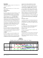
The Bard th-Tune single unit controller can be used in
place of the LC-6000 controller when only one MULTI-
TEC wall-mount air conditioner is being controlled.
If using a th-TUNE single unit controller instead of
the PLC controller, the alarm logging and remote
communications capabilities of the LC6000 controller
will not be available.
For optimum temperature sensor performance, the th-
Tune controller should be mounted on an interior wall
and away from any heat sources, sunlight, windows,
air vents, air circulation obstructions and/or any other
cause of erratic or false temperature sensing.
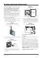
Mounting th-Tune Controller to Wall
1. Before performing any operations on the controller,
disconnect all power to the wall unit.
2. Separate the the front from the rear of the th-Tune
using a screwdriver (see Figure 11).
FIGURE 11
Separate Front of th-Tune from Rear
3. Disconnect the 4-pin connector from the front part
as shown in Figure 12.
FIGURE 12
Disconnect 4-Pin Connector
4. To remove cover A1 (Figure 13), unscrew screw,
press the point of attachment and separate cover
from base.
FIGURE 13
Remove Cover
A1
Remove this screw
Press here
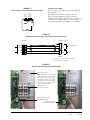
Power and Communications Wiring
Power Wiring
For the power wiring, use standard 18 gauge twisted
pair wiring.
Power wires from the th-Tune connect to a special
terminal block located next to the control board on
the wall unit control panel. This terminal block will be
labeled, “pAD Single Unit Controller” (see Figure 17).
When wiring power to the th-Tune from the wall unit,
ensure that G0 from the wall unit terminal is wired to
the GND terminal on the th-Tune power terminal block,
and G from the wall unit terminal is wired to the 24V
terminal on the th-Tune power terminal block. Failure
to wire these correctly will result in damage to the PLC
and th-Tune controller.
See Figures 15 and 16 for guidance with connecting
the power and communications wires.
5. Drill the mounting holes in the wall (see Figure
14), then insert the plugs and screws supplied,
making sure that the electrical wires pass through
hole in base. The th-Tune may also be installed
on a 2 x 4 handi box to allow for wiring to be in
conduit.
E
5.16"
3.29"
3.38"
FIGURE 14
th-Tune Base Dimensions
Manual 2100-678
Page 20 of 24
TH-TUNE CONTROLLER INSTALLATION
Page is loading ...
Page is loading ...
Page is loading ...
Page is loading ...
-
 1
1
-
 2
2
-
 3
3
-
 4
4
-
 5
5
-
 6
6
-
 7
7
-
 8
8
-
 9
9
-
 10
10
-
 11
11
-
 12
12
-
 13
13
-
 14
14
-
 15
15
-
 16
16
-
 17
17
-
 18
18
-
 19
19
-
 20
20
-
 21
21
-
 22
22
-
 23
23
-
 24
24


Bard MULTI-TEC W42AAPA Installation Instructions Manual
- Type
- Installation Instructions Manual
Ask a question and I''ll find the answer in the document
Finding information in a document is now easier with AI
Related papers
-
Bard MULTI-TEC W42AAPA Service Instructions Manual
-
-
-
-
Bard W36AA-C Installation Instructions Manual
-
-
-
Bard W24L2 User manual
-
Bard W36AB-C Series Installation Instructions Manual
-
Bard W38H1-B Installation Instructions Manual
Other documents
-
Jones Stephens A04006 Installation guide
-
Pro-Ject Wallmount it 1 Product information
-
-
-
 Hontech HT-A05 User manual
-
 Hontech HT-C06 User manual
-
LG LXN0446QC.ANONE Owner's manual
-
-
-
3D Connexion mD4000-b User manual

