Wacker Neuson PS45503 User manual

Type
User manual

This manual is also suitable for

Operator’s Manual
Pump
PS 3-Phase Pumps
5000190294 04 0719
5000190294
EN
Copyright
notice
© Copyright 2019 by Wacker Neuson Production Americas LLC
All rights, including copying and distribution rights, are reserved.
This publication may be photocopied by the original purchaser of the machine. Any
other type of reproduction is prohibited without express written permission from
Wacker Neuson Production Americas LLC.
Any type of reproduction or distribution not authorized by Wacker Neuson Production
Americas LLC represents an infringement of valid copyrights. Violators will be
prosecuted.
Trademarks
All trademarks referenced in this manual are the property of their respective owners.
Manufacturer
Wacker Neuson Production Americas LLC
N92W15000 Anthony Avenue
Menomonee Falls, WI 53051 U.S.A.
Tel: (262) 255-0500 · Fax: (262) 255-0550 · Tel: (800) 770-0957
www.wackerneuson.com
Original
instructions
This Operator’s Manual presents the original instructions. The original language of this
Operator’s Manual is American English.
wc_tx004643en.fm 3
CALIFORNIA Proposition 65 Warning
WARNING
The engine exhaust from this product contains chemicals known to the State of
California to cause cancer, birth defects, or other reproductive harm.
WARNING
Diesel engine exhaust and some of its constituents are known to the State of
California to cause cancer, birth defects, and other reproductive harm.
WARNING
Cancer and Reproductive Harm -
www.P65Warnings.ca.gov.
WARNING
Batteries, battery posts, terminals and related accessories contain lead and lead
compounds, and other chemicals known to the State of California to cause cancer
and birth defects or other reproductive harm. WASH HANDS AFTER HANDLING.
CALIFORNIA Proposition 65 Warning Proposition 65 Warning
4 wc_tx004643en.fm
This page is intentionally left blank.
wc_tx000001gb electric.fm
3
PS 3-Phase Pump Foreword
Foreword
This manual provides information and procedures to safely operate and maintain
this Wacker Neuson model. For your own safety and protection from injury,
carefully read, understand and observe the safety instructions described in this
manual.
Keep this manual or a copy of it with the machine. If you lose this manual or need
an additional copy, please contact Wacker Neuson Corporation. This machine is
built with user safety in mind; however, it can present hazards if improperly
operated and serviced. Follow operating instructions carefully! If you have
questions about operating or servicing this equipment, please contact Wacker
Neuson Corporation.
The information contained in this manual was based on machines in production at
the time of publication. Wacker Neuson Corporation reserves the right to change
any portion of this information without notice.
All rights, especially copying and distribution rights, are reserved.
Copyright July 30, 2019 by Wacker Neuson Corporation.
No part of this publication may be reproduced in any form or by any means,
electronic or mechanical, including photocopying, without express written
permission from Wacker Neuson Corporation.
Any type of reproduction or distribution not authorized by Wacker Neuson
Corporation represents an infringement of valid copyrights and will be prosecuted.
We expressly reserve the right to make technical modifications, even without due
notice, which aim at improving our machines or their safety standards.
wc_tx000001gb
4
Foreword PS 3-Phase Pump
This page is intentionally left blank.
wc_bo5000190294_04TOC.fm
5
PS 3-Phase Pump Table of Contents
CALIFORNIA Proposition 65 Warning 3
Foreword 3
1 Safety Information 7
1.1 Signal Words Used in this Manual ................................................................ 7
1.2 Operating and Electrical Safety ..................................................................... 8
1.3 Label Meanings ............................................................................................. 8
2 Operation 9
2.1 Components .................................................................................................. 9
2.2 Prior to Operation ........................................................................................ 10
2.3 Installation ................................................................................................... 10
2.4 Critical Pressure .......................................................................................... 11
2.5 Preparing for installation .............................................................................. 11
2.6 Checks to Make Before Installation ............................................................. 12
2.7 Precautions During Installation .................................................................... 12
2.8 Electrical Wiring ........................................................................................... 14
2.9 Cable Assembly .......................................................................................... 14
2.10 Connecting the Power Supply ..................................................................... 15
2.11 Wiring Diagram ............................................................................................ 16
2.12 Before Operation ......................................................................................... 16
2.13 Trial Operation ............................................................................................. 17
2.14 Operating current ........................................................................................ 17
2.15 Operating voltage ........................................................................................ 17
2.16 Vibration ..................................................................................................... 18
2.17 Operation ..................................................................................................... 18
2.18 Motor Protector ............................................................................................ 19
2.19 Water Level During Operation ..................................................................... 20
3 Maintenance 21
3.1 Periodic Maintenance Schedule .................................................................. 21
3.2 Maintenance and Inspection ....................................................................... 22
3.3 Storage ........................................................................................................ 22
3.4 Lubricant Inspection and Changing Procedures ......................................... 23
3.5 Changing Lubricant ..................................................................................... 24
3.6 Replacement Parts ...................................................................................... 24
3.7 Disassembly and Reassembly .................................................................... 25
3.8 2 / 3 / 5 / 7.5 HP Components ..................................................................... 26
6
Table of Contents PS 3-Phase Pump
3.9 10 HP and 15 HP Components ................................................................... 29
3.10 10 HP and 15 HP Components Description ................................................ 30
4 Troubleshooting 32
5 Technical Data 33
5.1 Standard Specifications ............................................................................... 33
5.2 Operating Specifications ............................................................................. 33
6 AEM Safety Manual 37
wc_si000044gb.fm
7
PS 3-Phase Pump Safety Information
1 Safety Information
1.1 Signal Words Used in this Manual
This manual contains DANGER, WARNING, CAUTION, NOTICE,
and NOTE signal words which must be followed to reduce the
possibility of personal injury, damage to the equipment, or improper
service.
NOTICE: Used without the safety alert symbol, NOTICE indicates a
situation which, if not avoided, could result in property damage.
Note: A Note contains additional information important to a procedure.
This is the safety alert symbol. It is used to alert you to potential personal hazards.
Obey all safety messages that follow this symbol.
DANGER
DANGER indicates a hazardous situation which, if not avoided, will result in death
or serious injury.
To avoid death or serious injury from this type of hazard, obey all safety mes-
sages that follow this signal word.
WARNING
WARNING indicates a hazardous situation which, if not avoided, could result in
death or serious injury.
To avoid possible death or serious injury from this type of hazard, obey all
safety messages that follow this signal word.
CAUTION!
CAUTION indicates a hazardous situation which, if not avoided, could result in
minor or moderate injury.
To avoid possible minor or moderate injury from this type of hazard, obey all
safety messages that follow this signal word.
wc_si000044gb.fm
8
Safety Information PS 3-Phase Pump
1.2 Operating and Electrical Safety
This pump has not been investigated for use in swimming pool areas.
An acceptable motor-control switch shall be provided at the time of
installation according to local codes and regulations.
1.3 Label Meanings
WARNING
Electric shock hazard.
To reduce risk of electric shock, connect only to a properly grounded, ground-
ing-type receptacle.
To reduce risk of electric shock, follow instructions in this manual for proper
installation.
CAUTION!
Electric shock hazard. This pump may automatically restart.
Prior to working on the pump or control panel, all supply circuits must be discon-
nected.
Do not remove cord and strain relief.
A nameplate listing the model number, item number, revi-
sion number, and serial number is attached to each unit.
Please record the information found on this nameplate so it
will be available should the nameplate become lost or dam-
aged. When ordering parts or requesting service informa-
tion, you will always be asked to specify the model number,
item number, revision number, and serial number of the
unit.
California Proposition 65 Warning
Cancer and Reproductive Harm -
www.P65Warnings.ca.gov.
Cancer and Reproductive Harm
www.P65Warnings.ca.gov
Cáncer y daño reproductivo
www.P65Warnings.ca.gov
Cancer ou malformations
congénitales
www.P65Warnings.ca.gov
WARNING
AVERTISSEMENT
ADVERTENCIA
5100045462
wc_tx0003911gb.fm
9
PS 3-Phase Pump Operation
2 Operation
2.1 Components
wc_gr000327
7
1
2
8
9
10
11
12
13
14
6
5
4
3
wc_tx0003911gb.fm
10
Operation PS 3-Phase Pump
Note: This diagram shows the parts layout of a typical PS (Three-Phase) model. The external appear-
ance and the internal construction may vary slightly, depending on your particular model.
2.2 Prior to Operation
When the pump is delivered, first perform the following inspection
checks:
While unpacking, inspect the product for damage during ship-
ment, and make sure all bolts and nuts are tightened properly.
Check the model number to make sure it is the product that was
ordered. Be certain it is the correct voltage and frequency.
Note: If there is any problem with the product as shipped, contact
your nearest dealer or Wacker Neuson representative at once.
2.3 Installation
If the pump is used to drain a swimming pool, the pump must be
connected to a Ground Fault Interruptor (GFI).
If the pump is used in fountains, the pump must be connected to a
Ground Fault Interruptor (GFI).
The pump must not be used when people are in the water.
Leakage of pump lubricants may cause pollution of water.
Proper plug must be provided according to local codes and standards.
Refer to wiring diagram.
The supply voltage should be within ± 5% of the rated voltage.
Ref. Description Ref. Description
1 Discharge outlet 8 Lifting handle
2 Coupling 9 Mechanical seal
3 Oil housing 10 Oil plug
4 Lubricant 11 Sleeve
5 Impeller 12 Volute
6 Suction cover 13 Strainer
7 Cable assembly 14 Plate
CAUTION!
Personal injury hazard. Failure to observe this caution can lead to electrical shock,
current leakage, fire, water leakage, or other problems.
Do not operate this product under any conditions other than those for which it is
specified.
WARNING
wc_tx0003911gb.fm
11
PS 3-Phase Pump Operation
DO NOT use in water temperatures outside the range of 0–40°C (32–
104°F), which can lead to failure, electrical leakage or shock.
The pump should be used only for pumping plain water. The pump
should not be used to pump fluids such as oil, salt water, or organic
solvents.
The pump must never be used to pump explosive liquids and should
never be operated in an area where explosive elements might be
present.
The pump must not be used in a partially disassembled state.
Note: Consult your local dealer or Wacker Neuson representative
before using with any liquids other than those indicated in this
document.
2.4 Critical Pressure
Do not use the pump in an area where the water pressure exceeds the
values given below, as it may damage the pump, or cause a short or
electrical shock.
2.5 Preparing for installation
Before installing the pump at a work site, you will need to have the
following tools and instruments ready:
Insulation resistance tester (megohmmeter)
AC voltmeter
AC ammeter (clamp-on type)
Bolt and nut tighteners
Power supply connection tools (screwdriver or box wrench)
Note: Please also read the instructions that come with each of the test
instruments.
Model Critical Pressure
PS2 1503
PS2 2203
PS2 3703
PS4 3703
PS4 5503
PS3 1503
PS3 2203
PS3 3703
PS3 5503
0.5 MPa (71 PSI)
– discharge pressure during use
= critical pressure
PS4 7503HH
PS4 11003HH
PS4 7503HF
PS4 11003HF
critical pressure = 0.5 MPa (71 PSI)
CAUTION
wc_tx0003911gb.fm
12
Operation PS 3-Phase Pump
2.6 Checks to Make Before Installation
With the megohmmeter, measure the insulation resistance between
each of the power wires and grounding wire to verify the insulation
resistance of the motor.
Reference insulation resistance: 20M or greater
Note: The reference insulation resistance (20M
or greater) is the
value when the pump is new or has been repaired. For the reference
value after installation, see Maintenance and Inspection.
2.7 Precautions During Installation
2.7.1 The pump is supplied with a threaded discharge fitting. Tighten hose
coupling or discharge pipe securely and with proper gaskets.
When installing the pump, be mindful of the pump’s center of gravity
and weight. If the pump is not suspended properly, the pump may fall
and break, which may lead to injury.
When installing or moving the pump, do not suspend the pump by the
cable assembly. Doing so will damage the cable, which may cause a
short, electrical shock, or fire.
When transporting the pump manually, be sure to have a sufficient
number of people to carry out the task. To prevent back injury when
lifting, bend your knees without bending your back.
2.7.2 Handle the pump carefully. Do not drop it or expose it to strong
impacts. When suspending the pump to raise or to lower it, attach a
wire rope (a) or a chain to the pump’s lifting handle.
Note: For proper procedures for handling the cable assembly, refer to
“Electrical Wiring” in this manual.
Do not operate the pump dry. Doing so will prevent the pump from
attaining its full potential and may also damage the pump and lead to
a short and electrical shock.
In order to properly discharge water, provide adequate piping to the
area where the pump is mounted. Improper piping may lead to water
leakage or other malfunctions.
2.7.3 Install the pump only in an area that can maintain a proper water level.
Note: For details on the water level necessary for pump operation,
refer to “Water Level During Operation” in Operation.
WARNING
CAUTION
CAUTION
wc_tx0003911gb.fm
13
PS 3-Phase Pump Operation
2.7.4 When using a hose to provide piping to the pump, observe the
following:
Use the shortest possible length of discharge hose and minimize the
number of bends. Verify that the end of the hose (discharge side) is
lifted above the water surface (b). If the end of the hose is submerged
in water, it may cause the water to flow back (c) when the pump has
been stopped. If the end of the hose is located at a level that is lower
than that of the source water surface, water may continue to flow out
even after the pump has been stopped.
Note: Appropriate piping materials must be provided by the user.
Piping materials are not included with the product.
If an excessive amount of sediment is drawn into the pump, it may
cause the pump to wear, which can lead to current leakage or electrical
shock.
2.7.5 The pump must be placed upright during operation. If there is a risk
that the pump could be buried under the sediment, place the pump on
a base made up of materials such as concrete blocks.
2.7.6 If used in a permanent installation, where the pump is not readily
accessible after installation, please contact Wacker Neuson for a
duplicate nameplate to be installed at the wellhead or on the control
box so that it will be readily visible.
wc_gr000330
wc_gr000329
b
c
wc_gr000328
a
wc_tx0003911gb.fm
14
Operation PS 3-Phase Pump
2.8 Electrical Wiring
Always make sure the pump is equipped with the specified overload
protectors and fuses or breakers, so as to prevent electrical shock
from a current leak or pump malfunction.
Operate within the capacity of the power supply and wiring.
2.9 Cable Assembly
If it is necessary to extend the cable assembly, use a core size equal
to or larger than the original. This is necessary not only to avoid a
performance drop, but to prevent cable overheating which can result in
fire, electrical leakage or electrical shock.
If a cable with cut insulation or other damage is submerged in the
water, there is a danger of damage to the pump, electrical leakage,
electrical shock, or fire.
Be careful not to let the cable assembly be cut or become twisted. This
may result in damage to the pump, electrical leakage, electrical shock,
or fire.
If it is necessary to submerge the connection wires of the cable
assembly in water, first seal the wires completely in a molded
protective sleeve, to prevent electrical leakage, electrical shock, or fire.
Do not allow the cable assembly wires or power supply plug to become
wet.
Make sure the cable does not become excessively bent or twisted, and
does not rub against a structure in a way that might damage it.
If used in a deep-well installation, the cable assembly should be
secured every 6 m (20 ft.).
WARNING
Personal injury hazard. Incorrect wiring can lead to current leakage, electrical
shock or fire.
Electrical wiring should be connected by a qualified person in accordance with all appli-
cable regulations. Failure to observe this precaution not only risks breaking the law but
is extremely dangerous.
WARNING
Electrical shock hazard. Failure to ground the pump properly can lead to electrical
shock from a current leak or pump malfunction.
Do not attach the grounding wire to a gas pipe, water pipe, lightning arrester or
telephone grounding wire.
CAUTION
wc_tx0003911gb.fm
15
PS 3-Phase Pump Operation
2.10 Connecting the Power Supply
Before connecting leads to the terminal strip, make certain the power
supply is turned off (circuit breaker, etc.), to avoid electrical shock,
shorting, or unexpected starting of the pump, leading to injury.
2.10.1 Tighten the ends of the cable assembly securely against the terminal
board.
2.10.2 The figure shows how to connect the cable assembly properly.
Wire Colors
B Black R Red Y Yellow Or Orange
G Green T Tan Br Brown Pr Purple
L Blue V Violet Cl Clear Sh Shield
P Pink W White Gr Gray LL Light blue
WARNING
U
V
W
G
R
W
B
G
wc_gr000331
wc_tx0003911gb.fm
16
Operation PS 3-Phase Pump
2.11 Wiring Diagram
Direct-on-LIne Starting
NOTICE: If connected to a circuit protected by a fuse, use a time-
delay fuse with this pump.
2.12 Before Operation
Improper voltage and frequency of the power supply will prevent the
pump from attaining its full potential, and may also lead to current
leakage, electrical shock, or fire.
2.12.1 Once again, check the nameplate of the pump to verify that its voltage
and frequency are correct.
2.12.2 Check the wiring, power supply voltage, the capacity of the ground
leakage circuit breaker, and the insulation resistance of the motor.
Insulation resistance reference value = 20MW min.
Note: The insulation reference value of 20MW min. is based on a new
or repaired pump. For reference values for a pump that has already
been installed, refer to Maintenance and Inspection in this manual.
Ref. Description Ref. Description
1 Coil 2 Circle thermal protector
Wire Colors
B Black R Red Y Yellow Or Orange
G Green T Tan Br Brown Pr Purple
L Blue V Violet Cl Clear Sh Shield
P Pink W White Gr Gray LL Light blue
CAUTION
wc_tx0003911gb.fm
17
PS 3-Phase Pump Operation
2.12.3 Adjust the setting of the overload protector (i.e. circuit breaker) to the
pump’s rated current.
Note: Verify the rated current on the pump’s nameplate.
2.12.4 When using a generator, as much as possible avoid operating the
pump in conjunction with other types of equipment.
2.13 Trial Operation
NEVER start the pump while it is suspended, as the pump may jerk
and cause a serious accident involving injury.
NEVER start the pump where people are present, as they may suffer
electrical shock from current leakage.
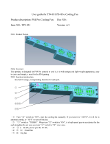
Be sure to check the pump’s direction of rotation when the pump is
exposed to atmosphere (a). Utilize a hoist to stabilize the pump on a
level surface while performing this check. Operating the pump in
reverse while it is submerged in water will damage the pump, which
may lead to current leakage, electrical shock, or fire.
2.13.1 The impeller will rotate counterclockwise (b), as viewed from the
bottom of the pump. Operate the pump for a short time (1 to 2 seconds)
to check the rotational direction of the impeller.
Before changing the connections for reverse rotation, make sure that
the power supply (i.e. circuit breaker) is properly disconnected and that
the impeller has stopped completely. Failure to observe this may lead
to serious accidents, including electrical shock, short, or injury.
To reverse the rotation, the following countermeasure must be taken.
COUNTERMEASURE: Interchange two of the three wires designated
U, V and W respectively (c), or follow control system manufacturer's
instructions to utilize rotary field control and phase inverter function of
the control system supplied with the pump.
2.13.2 Operate the pump for a short time (3 to 10 minutes) and perform the
following checks.
2.14 Operating current
Using an AC ammeter (clamp), measure the current at the phases U,
V, and W that are connected to the terminal board.
COUNTERMEASURE: Because an overload condition may be
present at the motor if the operating current exceeds the rated current,
refer to Section Installation in this manual for procedures on reverting
the motor to the correct state.
2.15 Operating voltage
Use an AC voltmeter (tester) to measure the voltage at the terminal
board.
Power supply voltage tolerance = within ±5% of the rated voltage
WARNING
CAUTION
WARNING
wc_tx0003911gb.fm
18
Operation PS 3-Phase Pump
COUNTERMEASURE: If the power supply voltage deviates from the
tolerance value, the deviation may be caused by the capacity of the
power supply or the extension cable that is used. Refer to Section
Electrical Wiring in this manual to provide correct voltage.
2.16 Vibration
If the pump generates a considerable amount of vibration, noise, or
smell, disconnect the power supply immediately and contact the dealer
where you purchased the equipment, or the Wacker Neuson sales
office in your area.
2.17 Operation
The pump may be extremely hot during operation. To prevent burns,
do not touch the pump with bare hands.
Do not insert your finger or a stick into the pump’s inlet opening. Doing
so may cause injury, electrical shock, short, or fire.
When the pump is not used for a long time, make sure that the power
supply (such as a breaker) is properly disconnected. If the wiring
insulation deteriorates with the power supply connected, it may cause
current leakage, electrical shock, or fire.
Pay attention to the water level during the pump operation. The pump
will become damaged if it is allowed to operate dry.
Note: Refer to “Water Level During Operation” at the end of this
section.
The pump is equipped with an internal motor protective device (circle
thermal protector).
CAUTION
U
V
W
G
wc_gr000333
cba
CAUTION
  • Page 1 1
  • Page 2 2
  • Page 3 3
  • Page 4 4
  • Page 5 5
  • Page 6 6
  • Page 7 7
  • Page 8 8
  • Page 9 9
  • Page 10 10
  • Page 11 11
  • Page 12 12
  • Page 13 13
  • Page 14 14
  • Page 15 15
  • Page 16 16
  • Page 17 17
  • Page 18 18
  • Page 19 19
  • Page 20 20
  • Page 21 21
  • Page 22 22
  • Page 23 23
  • Page 24 24
  • Page 25 25
  • Page 26 26
  • Page 27 27
  • Page 28 28
  • Page 29 29
  • Page 30 30
  • Page 31 31
  • Page 32 32
  • Page 33 33
  • Page 34 34
  • Page 35 35
  • Page 36 36
  • Page 37 37
  • Page 38 38
  • Page 39 39
  • Page 40 40
  • Page 41 41
  • Page 42 42
  • Page 43 43
  • Page 44 44
  • Page 45 45
  • Page 46 46
  • Page 47 47
  • Page 48 48
  • Page 49 49
  • Page 50 50
  • Page 51 51
  • Page 52 52
  • Page 53 53
  • Page 54 54
  • Page 55 55
  • Page 56 56
  • Page 57 57
  • Page 58 58

Wacker Neuson PS45503 User manual

Type
User manual
This manual is also suitable for

Ask a question and I''ll find the answer in the document

Finding information in a document is now easier with AI