Page is loading ...

VAPOR
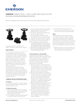
Thermally
Responsive
Fluid
BULB
CAPILLARY
TUBING
SPRING
BELLOWS
Thermally
Responsive
Fluid
VALVE PLUG SEATS
DIRECT ACTING
VALVE PLUG SEATS
Temp.
Below
Set Point
Temp.
Above
Set Point
REVERSE ACTING
VALVE
PLUG
VALVE
PLUG
VALVE
PLUG
VALVE
PLUG
IS-P-595DB
Instructions for Installing
#11 Regulator
Double Seat - Balanced Valve - Bronze (Type DB)
or Stainless Steel Trim (Type DS)
WARNING
!
Read this Manual BEFORE using this equipment.
Failure to read and follow all safety and use information
can result in death, serious personal injury, property
damage, or damage to the equipment.
Keep this Manual for future reference.
Valve Description
The Powers #11 Double Seat Balanced Valve Regulator
(Bronze or Stainless Steel trim) is a self-actuating control valve
which automatically controls high temperature fluids at high
pressures without the use of external power. Adjust the set
point and the rugged self-operating #11 Regulator controls the
flow of heating or cooling medium (water or steam) to maintain
a constant temperature.
The instrument has a vapor pressure thermal system containing
a thermally responsive fluid. This thermal system rapidly senses
temperature changes at the bulb and accordingly positions the
valve plug, to regulate the flow of the heating or cooling medium
to maintain a desired temperature. The thermal system features
a two-ply brass bellows with six reinforcing ribs on the bellows
head and thick capillary tubing walls to ensure long operating life.
The Powers #11 DS and DB Regulators feature
• A double seated valve for handling high capacities
• A valve stem of highly polished corrosion resistant grade
316L stainless steel to decrease friction and reduce
hysteresis
• An adjusting nut mounted on ball bearings and a set point
adjusting rod to ease set point adjustments
• A set point reference scale to aid temperature adjustments
Operation
A bulb is connected to a bellows containing a thermally respon-
sive fluid. The bulb is inserted into fluid you are trying to control
(process fluid) to sense its temperature. The Regulator set point
is adjusted to allow sufficient flow of heating or cooling medium
(water or steam) through the valve to keep the process fluid at
the desired temperature.
Direct Acting (heating application)
(A) When the temperature of the process fluid drops below
the set point, the temperature of the thermally responsive fluid
decreases, which decreases the vapor pressure in the bulb/
bellows. The force of the resulting vapor pressure is less than
the spring force, so the bellows contract and the spring extends,
which raises the valve plug up from its seat. This increases the
flow of the heating medium (water or steam), which raises the
temperature of the process fluid.
(B) As the process fluid temperature increases toward or beyond
the desired set point, the temperature of the thermally responsive
fluid in the bulb increases, which causes the vapor pressure to
increase. This expands the bellows, compresses the spring, and
moves the valve plug down and closer to its seat, to reduce or
stop the flow of the heating medium.
Table of Contents
Valve Description....................................1
Operation .........................................1
Applications........................................2
Specifications ......................................2
Sizing and Selection .................................3
Water Capacities ....................................3
Steam Capacities ...................................4
Product Identification.................................5
Installation .........................................5
Maintenance . . . . . . . . . . . . . . . . . . . . . . . . . . . . . . . . . . . . . . . 6
Preventive Maintenance ..............................9
Troubleshooting.....................................9
Parts ............................................10
Dimensions .......................................13
Accessories.......................................15
Temp. Ranges/Bulb Sizes ............................15
Order Code.......................................17
Warranty Information ................................16
(A)
(C)
(B)
(D)

2
Powers #11 Balanced Valve Regulators are used to automatically
control hot or cold fluids at pressures up to 125 psi. The self-ac-
tuated regulator can easily be installed in any convenient location.
Among its applications are: hot water systems, fuel oil heaters,
heat exchangers, air drying rooms, and many industrial process-
es. Below are two typical applications.
Balanced valve regulators are well suited to heating applications
where the steam inlet pressure is under 125 psig and good shut-
off is not required.
Applications
Specifications
Valve Sizes:
1/2" to 1-1/2" (NPT)
PHYSICAL SPECS
Valve Plug Travel See Tables on page 13
Effective Bellows Area 7.8 sq. in (50.3 cm2)
Body Material Bronze
Body Rating ANSI Class 250
Connections Double Female Union w/NPT Threads
Style Double Seat
Maximum Body Temperature: 400°F (204°C)
OPERATING SPECS
Temperature Range See order code on page 15
Controlled Medium Steam or Water
Max. Differential Pressure See Tables on page 4
Max. Allowable Overheat Temp. 25°F (14°C) above temp. range
Max. Well Safe Pressure See Tables on page 11
Max. Body Pressure 250psi (17/24 kPa)
Shipping Weight See Table on page 10
Flow Characteristics Linear
Shutoff Class Rating ANSI Class II
Leakage 0.5% rated valve capacity
(C) When the temperature of the process fluid rises toward or
above the set point, the temperature of the thermally responsive
fluid increases, which increases vapor pressure in the bulb/bel-
lows. The resulting force of the vapor pressure is greater than the
spring force, so the spring contracts and the bellows expand to
push the valve plug downward, away from its seat. This increas-
es the flow of the cooling medium, which lowers the temperature
of the process fluid.
(D) As the process fluid temperature decreases toward or below
the desired set point, the temperature of the thermally responsive
fluid decreases, causing the vapor pressure to decrease. This
contracts the bellows and expands the spring to pull the valve
plug up towards its seat, to reduce or stop the flow of the cool-
ing medium.
Heat Exchanger Application (Cooling)
#11 Indicating Regulator
Double Seat
REVERSE ACTING
HEAT EXCHANGER
From
Process
Pump
Bulb in Well
Cooled Liquid
Cold Water Supply
Cooling Water Discharge
Quench Tank Application (Heating)
#11 Regulator
Double Seat DS
DIRECT ACTING
Bulb in Well
Steam

3
Proper sizing of the Regulator is essential for correct system
operation. An undersized Regulator will not allow sufficient flow
at maximum load. An oversized Regulator may cycle and will not
utilize the full valve stroke for efficient modulation of flow. This
results in poor control and shortened valve life (quicker deteriora-
tion of valve plug and seat). For these reasons, the correct sizing
of the Regulator for actual expected conditions is considered
essential for good control.
NOTE: For best valve performance, select a bulb that contains
your process set point in the upper third of its temperature range
(see page 16).
Size the #11 Regulator for actual rather than maximum condi-
tions. Do Not size according to piping conditions; piping systems
are designed for different criteria than process controls. Refer to
Powers document AE-1—“Valve Selection and Sizing”—for fur-
ther recommendations.
Maximum Operating Pressure Differential (differential for
fluid flow): In order for the process medium to flow, a pressure
drop must exist across the valve. “Pressure differential” is the dif-
ference in valve pressure between the inlet and outlet under flow
conditions. The greater the differential, the greater the flow at any
given plug position.
Though the regulator should be sized for actual conditions, you
need to know the available differential at maximum flow. For
optimum control, take as much differential as possible across the
valve.
Sizing and Selection
Maximum Water Capacities
Use a pressure drop of at least 25% of inlet pressure when sizing valves for water applications.
CAUTION
!
Do not exceed maximum pressure differentials for given valve sizes. The maximum differential is the pressure
the valve has against it at shutoff. Too large a differential can cause valve chatter and/or prevent shutoff.
Water Capacities --- GPM
VALVE SIZE AVAILABLE SIZING PRESSURE DIFFERENTIAL --- PSI Maximum ∆P - PSI
Cv 2 4 6 8 10 15 20 25 30 40 50 60 80 100 125 Bronze SS
1" 13.5 19 27 33 38 43 52 60 68 74 85 95 105 121 135 151 50 150
1-1/4" 22 31 44 54 62 70 85 98 110 120 139 156 170 197 220 246 50 150
1-1/2" 28 40 56 69 79 89 108 125 140 153 177 198 217 250 280 313 50 150
2" 53 75 106 130 150 168 205 237 265 290 335 375 411 474 530 593 50 125
Water Capacities --- L/S
VALVE SIZE AVAILABLE SIZING PRESSURE DIFFERENTIAL --- KPA Maximum ∆P - kPa
7 15 30 45 60 75 100 125 150 200 250 350 450 550 650 750 Bronze SS
1" 0.9 1.3 1.8 2.2 2.5 2.8 3.2 3.6 4 4.6 5.1 6.1 6.9 7.6 8.3 8.9 345 1034
1-1/4" 1.4 2 2.9 3.5 4.1 4.6 5.3 5.9 6.5 7.5 8.4 9.9 11 12 13 14 345 1034
1-1/2" 1.8 2.6 3.7 4.5 5.2 5.8 6.7 7.5 8.2 9.5 11 13 14 16 17 18 345 1034
2" 3.4 4.9 7 8.5 9.9 11 13 14 16 18 20 24 27 30 32 35 345 1034

4
CAUTION
!
Caution: Do not exceed maximum pressure differentials for the given valve sizes.
The maximum differential is the pressure the valve has against it at shutoff.
Too large a differential can cause valve chatter and/or prevent shutoff.
Steam Capacities
Use a pressure drop of 50% of absolute inlet pressure (gauge pressure + 15 psi) for steam applications.
Inlet Pressure - PSIG
2 5 10 15 25 50
VALVE SIZE AVAILABLE SIZING PRESSURE DIFFERENTIAL --- PSI
1 2 1 2 3 5 2 4 6 8 10 2 5 10 15 2 5 10 15 20 10 15 20 32.5
1" 161 225 176 245 296 372 276 382 457 516 563 304 468 630 732 353 547 747 881 958 980 1174 1326 1572
1-1/4" 263 366 286 400 483 606 450 623 746 841 917 495 762 1027 1192 575 891 1217 1436 1562 1596 1914 2161 2563
1-1/2" 335 466 364 509 614 771 573 792 949 1070 1167 630 970 1307 1517 732 1134 1549 1828 1987 2032 2436 2750 3261
2" 634 882 690 963 1163 1460 1084 1500 1796 2026 2209 1193 1836 2474 2872 1385 2147 2932 3459 3762 3846 4611 5206 6173
Inlet Pressure - kPa
15 30 70 15100 175 350
VALVE SIZE AVAILABLE SIZING PRESSURE DIFFERENTIAL --- PSI
5 15 5 10 15 30 5 10 15 35 70 10 25 50 100 10 25 50 100 140 10 50 150 250
1" 63 107 67 94 114 156 77 108 131 194 258 117 181 248 324 137 214 296 397 448 176 385 627 753
1-1/4" 103 174 109 153 185 254 125 175 213 315 420 190 295 404 529 224 349 482 647 730 287 627 1021 1228
1-1/2" 131 221 139 194 236 323 159 223 271 401 534 242 375 514 673 285 444 613 823 930 365 799 1300 1562
2" 247 418 263 368 446 612 301 422 513 760 1012 459 711 972 1274 539 841 1161 1558 1760 692 1512 2460 2957
Inlet Pressure - PSIG
VALVE
SIZE
75 100 125 150 175 200 Maximum ∆P - PSI
AVAILABLE SIZING PRESSURE DIFFERENTIAL --- PSI
Bronze SS
Size 10 25 35 45 10 25 35 57.5 70 82.5 95 107.5 50 150
1" 1167 1761 2015 2187 1328 2027 2338 2801 110 120 139 156 50 150
1-1/4" 1902 2870 3284 3564 2164 3303 3811 4565 140 153 177 198 50 150
1-1/2" 2420 3653 4180 4535 2754 4203 4850 5809 265 290 335 375 50 125
2" 4581 6915 7912 8585 5213 7956 9181 10995 134408 158819 18231 20642 50 150
Always use Stainless Steel trim above 50 psg inlet pressure
Inlet Pressure - kPa
VALVE
SIZE
500 100700 850 1000 1200 1400
AVAILABLE SIZING PRESSURE DIFFERENTIAL --- PSI Maximum ∆P - kPa
75 175 250 301 70 175 250 401 476 551 651 751
Bronze SS
1" 525 791 910 971 611 932 1084 1294 1537 1779 2102 2425 345 1034
1-1/4" 856 1289 1483 1583 995 1519 1767 2109 2504 2899 3425 3952 345 1034
1-1/2" 1089 1640 1887 2015 1267 1933 2249 2685 3187 3689 4359 5029 345 1034
2" 2061 3105 3573 3814 2398 3659 4257 5082 6033 6984 8252 9520 345 1034
Always use Stainless Steel trim above 350 kPa inlet pressure
Steam Capacities --- KG./HR.

5
Product Identification
A red label should be on the front face of the thermal system.
Figure 1.
This label contains information required to properly maintain,
service and order parts for this product. If there is no label, look
for a white label on the inside of the thermal system legs (Figure
2A) or the valve body vertical yoke (Figure 2B).
When replacing the original thermal assembly or valve body,
secure the old red label onto the valve or thermal system or ink
the number onto the body.
Installation
Tools Needed
• Straight slot screwdriver • 5/16” open end wrench
• 3/8” open end wrench • 7/16” open end wrench
• 13/16” open end wrench • 1-3/8” open end wrench
Position Valve
1. To insure proper system operation, thoroughly flush all piping
and valves to rid them of all scale, dirt and debris.
2. Select valve location with sufficient clearance to allow mainte-
nance. Install valve in line. The direction of the arrows on the
valve body must match the direction of the water or steam
flow.
For best results, we recommend installing the valve in a
horizontal line, and in the upright position with bellows head
above valve. The valve may also be installed in any position
within 90° of upright.
Install Bulb
3. Figure 3a shows proper bulb orientation. Figure 3b shows
the special bulb needed for upwards vertical positioning.
4. Figure 4. For any position, fully immerse the bulb in the flow
of the medium.
These instructions are for D style bulbs - for installation of other
styles, refer to tag attached to bulb.
5. Without a well: Remove bushing from the bulb and screw it
into the tank. Insert the thermostatic bulb through the bush-
ing and tighten the union nut.
With a well: Do not use bushing. Screw well into tank, insert
bulb directly into well, and tighten union nut.
Adjust Capillary Tubing
6. Coil the extra capillary, and position away from regulator
operation where it is subjected to room temperature only.
Adjust set point
All regulators are factory set to control near mid-range operating
temperature.
7. When adjusting the set point, make certain the heating medi-
um is flowing through the valve and is at the operating pres-
sure of the system.
8. Figure 5. Make all set point temperature changes by inserting
the temperature adjustment rod into one of the holes of the
adjusting nut assembly. (Use the temperature adjustment set-
ting scale only for reference)
To Raise the set point:
Turn rod left to right
(counterclockwise from top).
To Lower the set point:
Turn rod right to left
(clockwise from top).
2B. Valve Body Label
2A. Thermal System Label
WARNING
!
DO NOT kink, cut, sever or file the tubing. DO NOT discon-
nect tubing from bulb or bellows assembly. This can render
the thermal system inoperable and result in severe process
overheating.
5. Adjusting Set Point
WORD "TOP" ON FLAT SURFACE FACING UP
HEAD END
TOP
Standard Bulb
Downward Vertical (left)
or
Horizontal (below)
Only
Special Bulb
Upward Vertical
Only (right)
3A. Bulb Orientation
3
B. Special Bulb
Correct: Bulb in flow of medium
Incorrect: Bulb not in flow of medium
4. Bulb Positions

6
Maintenance
DA: To only replace the valve plug
1. Before disassembly, the bulb must be cooled 30°F (16°C)
below the lowest point on the thermal system range, and flow
through the valve must be stopped.
2. Figure 5. Relieve all pressure on the spring by turning adjust-
ing nut assembly [31] fully right to left (clockwise from top).
3. Figure 6A. 1" to 2" valves: Use 1-3/8" wrench to loosen lock
nut [11]. Then, use 1-3/8" wrench to unscrew bonnet [20]
from valve body [26]. DO NOT ALLOW the regulator top to
rotate.
Lift up regulator top.
5. Remove stem retainer [22] and replace poppet assembly [24]
6. 1” to 2” valves: Install a new gasket [21] between bonnet and
valve body.
7. Replace bonnet and stem into valve body.
8. With valve plug firmly seated, screw stem extension [4] to the
dimension shown in Figure 15 and tighten into place with hex
nut [12].
9. Assemble in reverse order.
9. Lift off yoke and bridge
Piston Plate
Assembly
3/8" Nut
Spring
5/16" Nut
8. Remove Piston Plate/Spring
7. Remove Housing and Thermal System
Body
Stem Head Retainer
Regulator & Yoke
Double Seated
Poppet Assembly
6A. (DA, 1" to 2" ) lift off regulator from valve body
DA/RA: To fully disassemble regulator from valve
1. Before disassembly, the bulb must be cooled 30°F (16°C)
below the lowest point on the thermal system range, and flow
through the valve must be stopped.
2. Figure 5. Relieve all pressure on the spring by turning adjust-
ing nut assembly [31] fully right to left (clockwise from top).
3. Figure 7. Remove housing bolts [6] and nuts [7] and tem-
perature adjustment setting scale [8] and lift off thermal sys-
tem [1] (housing, bellows, capillary, and bulb).
4. Figure 8. Using one 3/8" wrench and one 5/16" wrench,
carefully loosen and remove piston plate assembly [2,3] from
the stem extension [4].
Lift off spring [19].
5. Figure 9. Use 1-3/8" wrench to unscrew lock nut [11] and lift
off the yoke and bridge assembly [9].
Follow steps 1-5, To fully disassemble regulator from valve.
DA: To replace packing

7
Maintenance, cont.
To replace packing
6. Figure 10A.1" to 2": Loosen and remove bonnet [20] from
valve body [26].
7. Carefully pull out poppet [24] and stem assembly [30].
Check the stem. It must have a polished surface that is free
of roughness and pitting. Replace any parts if necessary.
8. Figure 13. Remove packing gland [14], and all packing com-
ponents [15a-15e].
9. Clean packing chamber, taking care not to scratch seating
surfaces. Be sure chamber is free of dirt and grease.
10. 1” to 2” valves: Install a new gasket [21] between bonnet
and valve body. Replace bonnet [20] and stem [30] into valve
body.
NOTE: You must replace the bonnet and stem before
attempting to insert the packing. Otherwise, you may tear the
packing rings.
11. For standard packing kits, install the parts as shown in Figure
13.
Slide part(s) [15e], followed by [15d] and [15c] over the stem.
Gently push them into the packing chamber.
NOTE: Some kits do not include all the listed packing parts
(see page 12), but the order for part installation is the same.
12. For EP V-rings, lubricate the rings first.
Slide each V-ring [15b] over the stem and carefully push it
into the packing chamber.
13. Place the packing gland spacer [15a] on top of the bonnet.
14. Thread the packing gland assembly [14] into the bonnet.
Tighten the gland assembly against the spacer.
15. With valve plug firmly seated (stem in full down position)
screw stem extension [4] to the dimension shown in Figure
15 and tighten into place with hex nut [12].
16. Assemble the remaining parts in reverse order.
RA: To replace the valve plug / replace the packing
Follow steps 1-5, To fully disassemble regulator from valve.
1. Figure 11. Use a 5/16" wrench on the flats of the stem exten-
sion [4] and a 7/16" wrench on the hex nut [12] to loosen
and remove them.
2. Figure 12A. 1” to 2” valves: Loosen and remove valve cap.
Check the stem. It must have a polished surface that is free of
roughness and pitting. Replace any parts if necessary.
3. Unscrew plug from the stem retainer and replace.
4. Figure 13. Remove packing gland [14], and all packing
components [15a-15e].
9. lift off yoke and bridge
Yoke and Bridge
Locknut
Double
Seated
Poppet
Assembly
Stem Head
Retainer
Bonnet
Body
10A,. (DA, 1" to 2") remove bonnet from valve
Stem
Body
Poppet Assembly
Anti Spin Sleeve
Stem Head Retainer
Valve Cap
12A. (RA, 1" to 2" ) remove valve cap
13. packing components
Packing Kit
(15a-e)
Packing Gland
Spacer
Bonnet
Packing
Gland

8
5. Clean packing chamber, taking care not to scratch seating
surfaces. Be sure chamber is free of dirt and grease.
6. Insert plug and stem in valve body.
NOTE: You must replace the plug and stem before attempt-
ing to insert the packing. Otherwise, you may tear the
packing rings.
7. 1” to 2” valves: Screw valve cap into place and tighten.
2-1/2” to 4" valves: Install a new gasket [21] between the
bottom cap and body. Hold the bottom cap in place and
secure with the four cap screws.
8. For standard packing kits, install the parts as shown in
Figure 13.
Slide part(s) [15e], followed by [15d] and [15c] over the stem.
Gently push them into the packing chamber.
NOTE: Some kits do not include all the listed packing parts
(see page 12), but the order for part installation is the same.
9. For EP V-rings, lubricate the rings first.
Slide each V-ring [15b] over the stem and carefully push it
into the packing chamber.
10. Place the packing gland spacer [15a] on top of the bonnet.
11. Thread the packing gland assembly [14] into the bonnet.
Tighten the gland assembly against the spacer.
12. Figure 14. With poppet firmly seated (see chart below for
position), screw stem extension to the dimension given and
tighten into place with hex nut.
13. Assemble in reverse order.
Top of Stem
Extension
Top of
Bonnet
Hex Nut
SEE TABLE BELOW
14. Stem extension dimensions
Stem Setting Dimension
(See Above)
Valve
Action
Valve Size
1"- 2"
DA
(Stem DOWN)
10-1/8" (+1/32, -0)
[257mm (+.79, -0)]
RA
(Stem UP)
10-11/32" (+0,-1/32)
[263mm (+0, -.79)]
Testing the Thermal System
If the valve is not responding to temperature change, test the
thermal system.
1. Stop the flow of fluid through the line.
2. DA: Raise the temperature of the bulb above the set point
temperature by placing it in a container of hot water. This will
cause the plug to fully seat.
RA: Raise the temperature of the bulb above the set point
temperature by placing it in a container of hot water.
This will cause the plug to fully open.
3. Figure 15. With the valve plug in the desired position, use a
felt tip pen to mark the position of the packing gland assem-
bly on the stem.
4. DA: Place the bulb in a pan of cool water. Cool the bulb 30°F
(16°C) below set point so the valve is fully open.
RA: Place the bulb in a pan of cool water. Cool the bulb to or
beyond the set point so the valve plug is seated.
5. Use the pen to mark the new position of the packing gland
assembly on the stem.
6. The distance between the marks is the valve plug travel.
This should correspond with the Travel value in the Valve
Dimensions table on page 14. No movement or only partial
movement indicates the thermal system is defective and
should be replaced with a new system.
Distance between two
marks = Valve Travel
13. valve travel measurement
WARNING
!
Failure of the #11's thermal system will cause a heating valve
to full open and a cooling valve to full close. If either of these
valve states results in an unsafe process condition, a high-lim-
it shutdown device, such as a Powers Aqua Sentry, should
be used.

9
WARNING
!
Failure of the thermal system will result in a constant rise in
temperature (or constant high temperature) of the fluid which
you are trying to control.
Preventive Maintenance
Once every three months, inspect the Regulator as follows:
1. Visually check for leaks from the valve body joints, piping-to-
valve connections, packing and stem areas
2. Visually check for excessive corrosion on the regulator,
including the bellows, capillary, bulb, thermal system legs,
bridge, and yoke. Also check for excessive corrosion on the
valve body.
3. Perform the instructions in Testing the Thermal System
Less than full valve travel may indicate a leak in the bellows,
capillary, or bulb, or other problems. This may result in exces-
sive temperature in the process.
4. Test the temperature adjusting nut assembly for freedom of
movement (see Adjust Set Point for instructions).
5. Remove bulb from the process fluid and check for excessive
corrosion, or erosion that may weaken the bulb and/or cause
thermal system failure.
Troubleshooting
• Erratic temperature control (valve cycles too hot/cold)
1. Valve sized incorrectly. Verify valve selection.
2. Regulator is controlling at incorrect set point. Refer to Adjust
Set Point.
3. Bulb is poorly positioned and/or oriented, and will not control
the actual temperature of the heating/cooling medium. Refer
to Install Bulb.
4. Incorrect type of bulb is being used. See Table on page 15.
5. The valve stem is sticking. Lubricate the stem.
6. The valve stem is bent. Refer to Maintenance for disassembly
instructions and replace.
7. Packing gland assembly too tight. Loosen packing gland nut.
8. Faulty or incorrect steam traps. Replace with correct steam
trap.
9. Very wet steam. Install a high pressure steam trap just ahead
of the valve to drain off condensate that collects in the steam
line.
• Regulator does not shut off
1. Pressure differential is greater than allowable pressure drop.
Refer to Water Capacities and Steam Capacities tables.
2. Plug and/or seat is worn. Refer to Maintenance. Replace seat
and/or valve body plug.
3. Foreign material between the plug and seat. Refer to
Maintenance. Clean.
4. Bulb is poorly positioned and/or oriented, and will not control
the actual temperature of the heating/cooling medium. Refer
to Install Bulb.
5. Incorrect type of bulb is being used. See Table on page 15.
6. Valve sized incorrectly, causing wire drawing and leakage.
Refer to Sizing Information.
7. Packing gland assembly is too tight, locking valve stem.
Loosen packing gland assembly and lubricate if desired.
8. Bent valve stem; need to replace. Refer to Maintenance for
disassembly instructions.
9. Thermal system failure. Refer to Testing the Thermal System.
10. Temperature adjusting nut assembly raised too high. Refer to
Adjust Set Point.
• Regulator controlling at too low a temperature
1. Temperature adjusting nut assembly raised too high. Refer to
Adjust Set Point.
2. Pressure differential is greater than allowable pressure drop.
Refer to Water Capacities and Steam Capacities tables.
• Valve "chatters"
1. Regulator installed with the flow of the control medium in
reverse of arrow direction on valve body.
2. Pressure differential too high, refer Water Capacities and
Steam Capacities tables for correct range.
3. Trapped condensate in line. Install a steam trap just ahead
of the regulator to drain off condensate that collects in the
steam line.
• Constant rise in process fluid temperature
1. DA (Heating Valve): A constant rise in temperature may
indicate the thermal system is leaking charge and/or the valve
has failed in a partially or fully open position. This would allow
a constant flow of heating medium, which would overheat the
fluid which you are trying to control.
2. RA (Cooling Valve): A constant rise in temperature may
indicate the thermal system is leaking charge, and or the
valve has failed in a partially or fully closed position. This
would slow or stop the flow of cooling medium which would
overheat the fluid which you are trying to control.

10
1e
1d
1c
17
1f
15c
14
15e
15d
15b
15a
1b
1a
3
18
2
19
4
6
7
31
12
13
20
30
11
8
5
15
9
10
Parts

11
Parts

12
Parts
VALVE PARTS DIRECT ACTING
ITEM DESCRIPTION 1" 1-1/4" 1-1/2" 2" QTY MATERIAL
20-30 Valve Assembly Refer to Order Code 1
20 Bonnet 594 499 594 499 594 468 594 456 1 Brass
21 O-ring 084 008 084 008 084 009 084 010 1 Silicone
Gasket (non asbestos) — — — — 1 Gasketing
Gasket (non asbestos) — — — — 2 Material*
22 Stem Head Retainer 603 012 603 012 603 012 — 1 Brass
Stem Head Retainer — — — 612 100 1 416 SS
23 Spacer Bushing (DB) 609019C 609 019 609019A 609019C 1 Brass
Spacer Bushing (DS) 609019C 609019C 609019C 609019A 1 Brass
23 Valve Stop Sleeve (DB) — — — — 1 Brass
Valve Stop Sleeve (DS) — — — — 1 Brass
24 Poppet Assy (DB) 603 003 604 003 605 003 594 354 1 (See Specs)
Poppet Assy (DS) 591 948 591 949 591 950 591 951 1 (See Specs)
26 Body/Seat Assy (DB) 594 509 594 494 594 482 594 461 1 (See Specs)
Body/Seat Assy (DS) 594 511 594 496 594 483 594 463 1 (See Specs)
27 Union Tail Piece 609 003 610 003 611 003 — 2 Brass
Union Tail Piece — — — 590 233 2 Bronze
28 Union Nut 609 004 610 004 611 004 590 234 2 Bronze
28 Screw — — — — 4 SS
Screw — — — — 8 SS
29 Valve Cap — — — — 1 (See Specs)
29a Blind Cap — — — — 1 Iron
29b Top Cap — — — — 1 Iron
30 Stem Assembly 594816E 594816E 594816E 594817A 1
VALVE PARTS REVERSE ACTING
ITEM DESCRIPTION 1" 1-1/4" 1-1/2" 2" QTY MATERIAL
20-30 Valve Assembly Refer to Order Code 1
20 Bonnet 594 499 594 499 594 468 594 456 1 Brass
21 O-ring 084 008 084 008 084 009 084 010 2 Silicone
21 Gasket — — — — 2 *
22 Stem Head Retainer 603 012 603 012 603 012 — 1 Brass
Stem Head Retainer — — — 612 100 1 416 SS
23 Valve Stop Sleeve (DB) 601 090 601 091 601 093 590 328 1 Brass
Valve Stop Sleeve (DS) 601 090 601 091 601 092 590 329 1 Brass
23a Anti- Spin Sleeve (DB) — — — — 1 Zn pltd Steel
Anti- Spin Sleeve (DS) — — — — 1 SS
23b Dowel Pin — — — — 1 Cd pltd Steel
23c Screw (1/4-20-x 1/4) — — — — 1 Steel
24 Poppet Assy (DB) 603 003 604 003 605 003 594 354 1
Poppet Assy (DS) 591 948 591 949 591 950 591 951 1
26 Body/Seat Assy (DB) 594 510 594 495 594 482 594 462 1
Body/Seat Assy (DS) 594 512 594 497 594 485 594 464 1
27 Union Tail Piece 609 003 610 003 611 003 — 2 Brass
Union Tail Piece — — — 590 233 2 Bronze
28 Union Nut 609 004 610 004 611 004 590 234 2 Bronze
28 Screw — — — — 4 SS
Screw — — — — 8 SS
29 Valve Cap 591 781 591 781 594 472 594 466 1 Brass
29a Blind Cap — — — — 1 Iron
29b Top Cap — — — — 1 Iron
30 Stem Assembly 594816E 594816E 594816E 594817A 1
1", 1-1/4", 1-1/2" & 2" REVERSE ACTING
1", 1-1/4", 1-1/2" & 2" DIRECT ACTING
30
20
27
28
26 24
29
26
28
27
30
20
22
24
23
22
21
21
23
1", 1-1/4", 1-1/2" & 2" REVERSE ACTING
1", 1-1/4", 1-1/2" & 2" DIRECT ACTING
30
20
27
28
26 24
29
26
28
27
30
20
22
24
23
22
21
21
23

13
Dimensions
ACTUAL WEIGHT (LBS.)
ENDS SIZE ACTION C */c ** (IN) D */d ** (IN) E (IN) TRAVEL (IN) NON INDIC. INDICATING
Double
Union
1”
DA 3 3/8 2 1/8 6 3/4 3/16 22 24
RA 3 3/8 2 3/4 6 3/4 1/4 22 24
1-1/4”
DA 3 5/8 2 1/2 7 1/4 24 26
RA 3 5/8 3 7 1/4 24 26
1-1/2”
DA 3 3/4 2 5/8 8 1/4 26 28
RA 3 3/4 3 1/4 8 1/4 26 28
2”
DA 4 7/8 3 5/8 9 5/8 3/8 36 39
RA 4 7/8 4 3/8 9 5/8 5/16 36 39
ACTUAL WEIGHT (KG.)
ENDS SIZE ACTION C */c ** (MM) D */d ** (MM) E (MM) TRAVEL
(MM)
NON INDIC. INDICATING
Double
Union
1”
DA 86 54 171 5 10 11
RA 86 70 171 6 10 11
1-1/4”
DA 92 64 178 6 11 12
RA 92 76 178 6 11 12
1-1/2”
DA 95 67 203 6 12 13
RA 95 83 203 6 12 13
2”
DA 124 92 244 10 16 18
RA 124 111 244 8 16 18
Valve Dimensions
Optional Indicating Style Head
D
11-5/8"
[296mm]
C
5" DIA.
[127mm]
CAPILLARY TUBING
8' [2.4m]
15' [4.6m]
30' [9.1m]
E
4-1/8
[108]
3-5/8" DIA
[87]
*DA **RA

14
J
A
A
A
BB
BB
BB
D Style Bulbs
J Style Bulbs
JD Style Bulbs
NPT Pipe Thread
NPT Pipe Thread
1" NPT Pipe Thread
F
G
H
K
(outer dim. of taper)
S Style Wells
J
A
A
A
BB
BB
BB
D Style Bulbs
J Style Bulbs
JD Style Bulbs
NPT Pipe Thread
NPT Pipe Thread
1" NPT Pipe Thread
F
G
H
K
(outer dim. of taper)
S Style Wells
J
A
A
A
BB
BB
BB
D Style Bulbs
J Style Bulbs
JD Style Bulbs
NPT Pipe Thread
NPT Pipe Thread
1" NPT Pipe Thread
F
G
H
K
(outer dim. of taper)
S Style Wells
Bulb Dimensions
MAX. PRESSURE - PSI
BULB SIZE MATERIAL A (IN) B (IN) SHOCK NON-SHOCK
D
Fixed Union
(& V-Vertical
Fixed Union)
1 x 9
Copper 15/16 8 175 250
347 Stainless 15/16 8 1/16 500 725
1 x 20
Copper 15/16 19 7/8 175 250
347 Stainless 15/16 19 13/16 500 725
J Plain Bulb*
1 x 9 347 Stainless 15/16 8 3/4 – –
1 x 20 347 Stainless 15/16 20 1/2 – –
JD Adjustable
1 x 9 347 Stainless 15/16 8 3/4 500 725
1 x 20 347 Stainless 15/16 20 1/2 500 725
MAX. PRESSURE - PSI
BULB SIZE MATERIAL A (IN) B (IN) SHOCK NON-SHOCK
D
Fixed Union
(& V-Vertical
Fixed Union)
1 x 9
Copper 24 203 4445 6350
347 Stainless 24 205 12700 18415
1 x 20
Copper 24 505 4445 6350
347 Stainless 24 503 12700 18415
J Plain Bulb*
1 x 9 347 Stainless 24 222 – –
Teflon Coated 24 222 – –
1 x 20 347 Stainless 24 521 – –
JD Adjustable
1 x 9 347 Stainless 24 222 12700 18415
1 x 20 347 Stainless 24 521 12700 18415
Well Dimensions
WELL PRESSURE - PSI
BULB SIZE WELL KIT # WELL MATERIAL F (IN) G (IN) H (IN) J (IN) K (IN) SHOCK NON-SHOCK
1 x 9
709 193 Chrome Plated Copper 15/16 13/16 9 1/16 1 1.11 175 250
808 478 316L Stainless Steel 1 1/16 13/16 8 11/16 1 1/64 1.11 450 675
1 x 20
709 075 Chrome Plated Copper 15/16 13/16 21 1/16 1 1.11 175 250
808 475 316L Stainless Steel 1 1/16 13/16 20 3/8 1 1/64 1.11 450 675
WELL PRESSURE - kPa
BULB SIZE WELL KIT # WELL MATERIAL F (MM) G (MM) H (MM) J (MM) K (MM) SHOCK NON-SHOCK
1 x 9
709 193 Chrome Plated Copper 24 21 230 25 28 1207 1724
808 478 316L Stainless Steel 27 21 221 26 28 3103 4654
1 x 20
709-075 Chrome Plated Copper 24 21 533 25 28 1207 1724
808-475 316L Stainless Steel 27 21 518 26 28 3103 4654

15
Accessories
KIT# MATERIAL VALVE SIZE STEM SIZE USAGE PARTS LUBRICANT
591 927 Teflon V-ring 1/2" – 2" 1/4"
Effective from 200°F-400°F S
team: 50 - 200 psi
15A, 15B, 15C,
15D, 15E
None
594 220 EP V-ring 1/2" – 2" 1/4"
Effective from 0°F-300°F
Steam: 50psi maximum
Water: up to maximum PSI valve rating
15A, 15B, 15C,
15D, 15E
Silicone required for installation
(optional for service)
594 289 TFE Split Ring 1/2" – 2" 1/4"
For replacement only
Effective from 40°F-366°F
15B, 15D
Silicone
Part #087 126
Temperature Ranges/Bulb Sizes
For ordering thermal systems, refer to order code, the Powers #11 Product Specification Brochure, or call Powers.
BULB
SIZE
BULB TEMP. RANGE ORDER
CODE
SINGLE OR DOUBLE SEAT VALVES 1/2” TO 2”
HEATING DA COOLINNG RA
1" x 20"
10–70°F (-12–21°C) 0-60°F (-18-16C) 01
55–115°F (13–46°C) 45-105°F (7-41°C) 02
80–145°F (29–63°C) 70-130°F (21-54°C) 03
90-150°F (32-66°C) 04
1" x 9"
110–170°F (43–77°C) 110-150°F (43-66°C) 05
130–190°F (54–88°C) - 06
140–200°F (60–93°C) 120-180°F (49-82°C) 07
170–230°F (77–110°C) 150-210°F (66-99°C) 08
200–250°F (93–121°C) 185-245°F (85-118°C) 09
230–290°F (110–143°C) 220-280°F (104-138°C) 10
270–330°F (132–166°C) 255-315°F (124-157°C) 11

IS-P-595DB 1942 EDP# 6509035 © 2019 Powers
USA: T: (800) 669-5430 • F: (847) 229-0526 • PowersControls.com
Canada: T: (905) 332-4090 • F: (905) 332-7068 • PowersControls.ca
Latin America: T: ((52) 55-4122-0138 • PowersControls.com
The Seller warrants that the equipment manufactured by it and covered by this order or contract is free from defects in material and workmanship and, without charge, equip-
ment found to be defective in material or workmanship will be repaired, or at Seller’s option replaced F.O.B. original point of shipment, if written notice of failure is received
by Seller within one (1) year after date of shipment (unless specically noted elsewhere), provided said equipment has been properly installed, operated in accordance with
the Seller’s instructions, and provided such defects are not due to abuse or decomposition by chemical or galvanic action. THIS EXPRESS WARRANTY IS IN LIEU OF AND
EXCLUDES ALL OTHER WARRANTIES, GUARANTEES, OR REPRESENTATIONS, EXPRESS OF IMPLIED. THERE ARE NO IMPLIED WARRANTIES OF MERCHANT-
ABILITY OR OF FITNESS FOR A PARTICULAR PURPOSE. The Seller assumes no responsibility for repairs made on the Seller’s equipment unless done by the Seller’s
authorized personnel, or by written authority from the Seller. The Seller makes no guarantee with respect to material not manufactured by it.
Order Code
595-
Valves Type
Double Seat Bronze Trim ..........................DB
Double Seat Stainless Trim .........................DS
Valve Sizes
1" ...........................................100
1-1/4" . . . . . . . . . . . . . . . . . . . . . . . . . . . . . . . . . . . . . . . . .125
1-1/2" . . . . . . . . . . . . . . . . . . . . . . . . . . . . . . . . . . . . . . . . .150
2" ...........................................200
Applications
Heating ......................................... H
Cooling ......................................... C
Bulb/Capillary Material & Length
Copper 8' . . . . . . . . . . . . . . . . . . . . . . . . . . . . . . . . . . . . . C08
Copper 15' .................................... C15
Copper 30' .................................... C30
Stainless Steel 8' ............................... S08
Stainless Steel 15' .............................. S15
Stainless Steel 30' .............................. S30
Bulb Size
Fixed Union...................................... D
No Pipe Fittings (N/A Copper).........................J
Adj. Union (N/A in H head) .......................... A
Fixed Union (D Type) Vertical .........................V
Head Assembly
Non-indicating.................................... N
Indicating.........................................I
Range/Bulb Size ..................................#
See chart on page 15
Select Range with Set Point in
UPPER THIRD for best performance.
Valve Assembly Thermal System Assembly
/