LG DLG3744W Owner's manual
- Category
- Electric laundry dryers
- Type
- Owner's manual
Page is loading ...

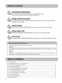
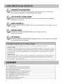
OUTSTANDING PERFORMANCE
Not to mention unmatched big capacity, you can benefit from good
time efficiency, quiet operation and energy saving system.
DOUBLE-COATEDSTEELDRUM
It is coated with one metal coating and the other polymer coating in order to guarantee high
durability and the long life.
ARTISTIC DESIGN
Modern front panel look and big crystal-clear glass door make your house look stylish.
DIGITAL FABRICCARE
Multi-level temperature control heater takes a better care on your valued clothes.
EASYOF USE
A whole selection of user-friendly functions always make you comfortable with dryer operation.
Your dryer provides sensor drying and time drying programs.
Sensor Dry
The dryer senses the dampness of the laundry and automatically determines the heat level and operation time. You might
see a sudden increase or decrease in operation time if the sensor determines more or less drying is required. This is not a
malfunction.
Time Dry
Use TIME DRY to select heat level and drying time manually. This can be used if clothes are not as dry as you like them
at the end of the cycle. Use TIME DRY for heavy and bulky items and thick work.
PART 1. SPECIFICATIONS ................................................................................................................................................................................................................. 3
PART 2. iMPORTANT WARRANTY AND SAFETY iNSTRUCTiONS ............................................................................................................................................... 4
PART 3. INmAL STEPS FOR iNSTALLING YOUR DRYER ............................................................................................................................................................ 11
PART 4. ACCESSORIES INSTALLATION ........................................................................................................................................................................................ 17
PART 5. ELECTRICAL REQUIREMENTS FOR ELECTRIC DRYERS .............................................................................................................................................. 19
PART 6. ELECTRICAL REQUIREMENTS FOR GAS DRYERS ......................................................................................................................................................... 23
PART 7. GAS REQUIREMENTS AND INSTRUCTIONS .................................................................................................................................................................... 24
PART 8. EXHAUST REQUIREMENTS AND MAINTENANCE ........................................................................................................................................................... 25
PART 9. OPERATING YOUR DRYER ................................................................................................................................................................................................ 27
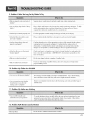
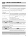
PART 10. TROUBLESHOOTING GUIDE ............................................................................................................................................................................................ 33
LG DRYER LIMITED WARRANTY ...................................................................................................................................................................................................... 36
2

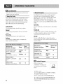
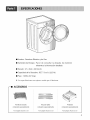
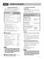
m Type : Electric and Gas Dryer
m Rating : Please refer to the rating label regarding detailed information.
m Size : 27 x 29.9 x 38.7(inch)
m Capacity : IEC 7.3 cu.ft. (22.5 Ib)
m Weight : 126 Ibs (57.2 kg)
÷ Specifications are subject to change by manufacturer.
,--m ACCESSORIES
Dryer Rack
Purchased Separately
Stacking Kit
Purchased Separately
:_ l)es_gn of pedesmL_ i,_ sul_ject to
change widtout manafatttrers notice.
Pedestal
Purchased Separately
See page 28,[br instructions. See page I5,[br instructions. Seepage I6 ,[br instructions.
J
3

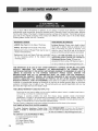
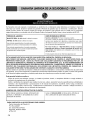
SEEKINGWARRANTYSERVICE
The warranty for your dryer is located at the end of this manual. Warranty Service is
available by contacting your nearest LG Service Center. If this product is installed and
operated according to the instructions in this manual, LG will repair or replace any parts
defective in material or workmanship throughout the warranty period, beginning with the
date of purchase.
WARNING!
For your safety, the recommendations in this manual must be followed. To reduce the risk
of fire or explosion, electric shock or to prevent property damage, personal injury, or death
when using your appliance follow basic precautions.
Warranty Restriction: If the dryer is subjected to other than single family use, all warranty
coverage is effective for only 90 days.
You will need the complete model and serial number when requesting warranty service, proof of
purchase date is required.
Use the space below to record the model number and serial number of your new LG dryer.
Model Number.
Serial Number.
Date of Purchase
_I_ Staple your receipt here for convenience when contacting service.

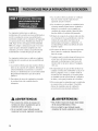
READALLINSTRUCTIONSBEFOREUSE
WARNING For yoursafety,theinformationinthis manualmustbefollowedto minimizetheriskoffire
orexplosion,electricshock,ortopreventpropertydamage,personalinjury,orlossof life.
YourSafety and the safety of others are very important,
We have provided many important safety messages in this manual and on your appliance.
Always read and obey all safety messages.
Thisis the safety alert symbol.
Thissymbol alerts you to potential hazards that can kill or hurt you and others.
All safety messages will follow the safety alert symbol and either the word DANGERor WARNING.
These words mean:
A DANGER Youcan be killed or seriously injured if you don't Immediately follow instructions.
,A WARNINGYoucan be killed orseriously injured ifyou don't follow instructions.
All safety messages will tell you what the potential hazard is, tell you how the reduce the
chance of injury, and tell you what can happen if the instructions are not followed.
r BASICSAFETYPRECAUTIONS
A WARNING
To reduce the risk of fire, electric shock or injuryto persons when usingyour
appliance, follow basic precautions, including the following :
• Read all instructions before using the dryer.
• Before use, the dryer must be properly installed
as described in this manual.
• Do not place items exposed to cooking oils in
your dryer. Items contaminated with cooking oils
may contribute to a chemical reaction that could
cause a load to catch fire.
Do not dry articles that have been previously
cleaned in, washed in, soaked in, or spotted with
gasoline, dry-cleaning solvents, other flammable
or explosive substances as they give off vapors
that could ignite or explode.
• Do not reach into the dryer if the drum is moving.
• Do not repair or replace any part of the dryer or
attempt any servicing unless specifically
recommended in this Use and Care Guide or in
published user-repair instructions that you
understand and have the skills to carry out.
• Do not tamper with controls.
• Beforethedryer is removedfromserviceor discarded,
removethe doortothedryingcompartment.
• Do not allow children to play on or in the dryer.
Close supervision of children is necessary when
the dryer is used near children.
• Do not use fabric softeners or products to
eliminate static unless recommended by the
manufacturer of the fabric softener or product.
• Do not use heat to dry articles containing foam
rubber or similarly textured rubber-like materials.
• Keep area around the exhaust opening and
adjacent surrounding areas free from the
accumulation of lint, dust, and dirt.
• The interior of the dryer and exhaust vent should
be cleaned periodically by qualified service
personnel.
• Do not install or store the dryer where it will be
exposed to the weather.
• Do not reach into the dryer while parts are
moving.
• Always checkthe insideof thedryerfor foreignobjects
• Clean lint screen before or after each load.
SAVETHESEINSTRUCTIONS

READALLINSTRUCTIONSBEFOREUSE
A WARNING For your safety, the information in this manual must befollowed to minimize the risk of
fire or explosion,electric shock, orto prevent propertydamage, personal injury, or loss
oflife.
• Do not store or use gasoline or other
flammable vapors and liquids in the vicinity
of this appliance or any other appliance.
• Installation and service must be performed
by a qualified installer, service agency, or
the gas supplier.
BASICSAFETYPRECAUTIONS
WARNING Toreduce the risk of fire, electric shock or injury topersons when using your
appliance, follow basic precautions, includingthe following"
GROUNDING INSTRUCTIONS
This appliance must be grounded.
In the event of malfunction or breakdown,
grounding will reduce the risk of electric shock
by providing a path of least resistance for
electric current. This appliance must be
equipped with a cord having an equipment-
grounding conductor and a grounding plug.
The plug must be plugged into an appropriate
outlet that is properly installed and grounded
in accordance with all local codes and
ordinances.
WARNING - Improper connection of the
equipment- rounding conductor can result in a
risk of electric shock. Check with a qualified
electrician or service person if you are in doubt
as to whether the appliance is properly
grounded.
Do not modify the plug provided with the
appliance.
If it will not fit the outlet, have a proper outlet
installed by a qualified electrician.
This appliance must be connected to a
grounded metal, permanent wiring system or an
equipment-grounding conductor must be run
with the circuit conductors and connected to the
equipment-grounding terminal or lead on the
appliance.
5

READALLINSTRUCTIONSBEFOREUSE
fire or explosion,electricshock, orto prevent propertydamage, personal injury, or loss
of life.
WHATTODOIF YOUSMELLGAS
1. Do not try to light a match or cigarette, or
turn on any gas or electrical appliance.
2. Do not touch any electrical switches.
Do not use any phone in your building.
3. Clear the room, building, or area of all
occupants.
4. Immediately call your gas supplier from a
neighbor's phone. Follow the gas supplier's
phone. Follow the gas supplier's
instructions carefully.
5. If you cannot reach your gas supplier, call
the fire department.
CALIFORNIASAFEDRINKINGWATERANDTOXICENFORCEMENTACT
This act requires the governor of California to publish a list of substances known to the state
to cause cancer, birth defects, or other reproductive harm and requires businesses to warn
customers of potential exposure to such substances.
Gas appliances can cause minor exposure to four of these substances, namely benzene,
carbon monxide, formaldehyde, and soot, caused primarily by the incomplete combustion of
natural gas or LP fuels.
Properly adjusted dryers will minimize incomplete combustion. Exposure to these substances
can be minimized further by properly venting the dryer to the outdoors.
7

READALLINSTRUCTIONSBEFOREUSE
X_ WARNING For your safety,the information in this manual must be followed tominimize the risk of
fire or explosion,electric shock, or to preventproperty damage, personal injury, or loss
of life.
SAFETYINSTRUCTIONFORINSTALLATION
appliance, follow basic precautions,including the f0110wing:
• Properly ground dryer to conform with
all governing codes and ordinances.
Follow details in the installation
instructions.
Electrical shock can result if the dryer is not
properly grounded.
• Before use, the dryer must be properly
installed as described in this manual.
Electrical shock can result if the dryer is not
properly grounded.
• Install and store the dryer where it will
not be exposed to temperatures below
freezing or exposed to the weather.
All repairs and servicing must be performed
by an authorized servicer unless specifically
recommended in this Owner's Guide.
Use only authorized factory parts.
Failure to follow this warning can cause
serious injury,fire, electrical shock or death.
• Do not install the washer in humid
spaces to reduce the risk of electric
shock.
Failure to follow this warning can cause
serious injury,fire, electrical shock or death.
• Connect to a properly rated, protected,
and sized power circuit to avoid
electrical overload.
Improper power circuit can melt, creating
electrical shock and/or fire hazard.
• Remove all packing items and dispose
of all shipping materials properly.
Failure to do so can result in death,
explosion, fire or burns.
• Place dryer at least 18 in. above the floor
for a garage installation.
Failure to do so can result in death,
explosion, fire or burns.
8

READALLINSTRUCTIONSBEFOREUSE
WARNING Foryour safety, the information in this manual must be followed to minimize the risk of
of life.
SAFETYINSTRUCTIONFORINSTALLATION(cont,)
Exhaust/Ducting:
• Gas dryers MUST be exhausted to the
outside.
Failure to follow these instructions can result
in fire or death.
• The dryer exhaust system must be
exhausted to the outside of the dwelling.
The dryer is not exhausted outdoors, some
fine lint and large amounts of moisture will
be expelled into the laundry area. An
accumulation of lint in any area of the home
can create a health and fire hazard.
• Use only rigid metal or flexible metal 4in.
Diameter ductwork inside the dryer
cabinet or for exhausting to the outside.
Use of plastic or other combustible ductwork
can cause a fire. Punctured ductwork can
cause a fire if it collapses or becomes
otherwise restricted in use or during
installation.
• Ductwork is not provided with the dryer,
and you should obtain the necessary
ductwork locally. The end cap should
have hinged dampers to prevent back
draft when the dryer is not in use.
Failure to follow these instructions can resul
in fire or death.
The exhaust duct must be 4 in. (10 cm)
in diameter with no obstructions. The
exhaust duct should be kept as short as
possible. Make sure to clean any old
ducts before installing your new dryer.
Failure to follow these instructions can result
in fire or death.
• Rigid or semi rigid metal ducting is
recommended for use between the dryer
and the wall. In special installations when
it is impossible to make a connection
with the above recommendations, a UL-
listed flexible metal transition duct may
be used between the dryer and wall
connection only. The use of this ducting
will affect drying time.
Failure to follow these instructions can result
in fire or death.
DO NOT use sheet metal screws or other
fasteners which extend into the duct that
could catch lint and reduce the efficiency
of the exhaust system. Secure all joints
with duct tape. 'I]U For complete details,
follow the Installation Instructions.
Failure to follow these instructions can result
in fire or death.
9

READALLINSTRUCTIONSBEFOREUSE
A WARNING F0ry0ur safety,the information in this manual must be followed to minimize the risk of
fire orexplosion,electric shock, or to prevent pr0perty damage, personal injury, 0r 10ss
0f life.
SAFETYINSTRUCTIONFORCONNECTINGELECTRICITY
A WARNING Toreduce the risk of fire, electric shock or injury to personswhen using the appliance,
follow basic precautions, includingthe following :
• Do not, under any circumstances, cut or
remove the ground prong from the power
cord.
To prevent personal injury or damage to the
dryer, the electrical power cord must be
plugged into a properly grounded
• For personal safety, this dryer must be
properly grounded.
Failure to do so can result in electrical shock
or injury
• Refer to the installation instructions in
this manual for specific electrical
requirements for your model.
Failure to follow these instructions can
create electrical shock and/or a fire hazard.
• This dryer must be plugged into a
properly grounded outlet.
Electrical shock can result if the dryer is not
properly grounded.
• Have the wall outlet and circuit checked
by a qualified electrician to make sure
the outlet is properly grounded.
This will prevent shock hazard and assure
stability during operating.
The dryer should always be plugged into
its own individual electrical outlet which
has a voltage rating that matches the
rating plate.
This provides the best performance and also
prevents overloading house wiring circuits
which could cause a fire hazard from
overheated wires.
• Never unplug your dryer by pulling on
the power cord. Always grip plug firmly
and pull straight out from the outlet.
The power cord can be cut by any
movement of the core, resulting in electrical
shock.
• Repair or replace immediately all power
cords that have become frayed or
otherwise damaged. Do not use a cord
that shows cracks or abrasion damage
along its length or at either end.
These power cord can melt, creating
electrical shock and/or fire hazard.
• When installing or moving the dryer, be
careful not to pinch, crush, or damage
the power cord.
This will prevent injury and damage to the
dryer from fire and electrical shock.
10

The following instructions will help guide you through the initial steps of setting up your dryer for use.
Please note that every section of this manual provides important information regarding the preparation and
use of your dryer, and it is important that you review this entire manual before proceeding with any
installation or use. More detailed instructions concerning electrical connections, gas connections, and
exhaust requirements are provided in other parts of this manual.
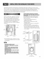
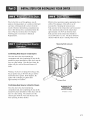
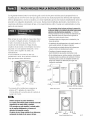
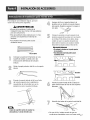
Choose a location with a solid floor for your dryer.
Place the dryer at least eighteen inches above the
floor for a garage installation. After placing the
dryer in the desired location, please make sure that
it has the required clearances shown below. If you
are installing your dryer in a manufactured or
mobile home, please refer to STEP 9 for additional
instructions.
38.7"
(98.3 cm)
/
49.8"
(126.4 cm)
27"
(68.6 cm)
* Most installations require a minimum 572 inches.
(14 cm) clearance behind the dryer for the exhaust
vent with elbow.
Leveling legs should be secured.
All four legs are stably placed on a solid and
even floor.
If dryer is not level, laundry may not tumble
properly and sensor will not detect accurate
humidity information.
When leveling, please be cautious not to injure
your fingers and toes.
If you install the dryer on the optional pedstal,
it is nessary to level with the pedestal leveling
legs.
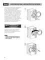
Certain minimum clearances are required
above, behind, and to the sides of the unit, as
shown below. Those required mininmm clearances
are set forth in the picture below. Please keep the
following instructions in mind when installing in a
closet or recessed area:
• Consider allowing additional clearance for
installation and servicing.
• Wall, door and floor molding may necessitate
additional clearances.
• An additional inch of clearance is recommended to
minimize noise transfer.
• Consider space needed for companion appliances.
• For closet installations, the picture below shows the
nlininmm required ventilation openings t_r the door.
A louvered door with comparable ventilation openings
is also acceptable.
3" /
(310 cm_)
2#*
(7.6cm) ......................................................
Closet Door
ventilation
hole
ventilation
hole
(2.54 cm) (76.1 cm) (2.54 cm)
Closet-side View
O"_ 27"
(0 cm) (68.6 cm)
Closet-flont View
(0 cm)
11

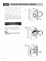
Once in position, adjust the leveling legs of the dryer
until it is level from left to right and front to back.
The leveling legs must remain firmly on the floor
and the dryer should not rock. The maximum slope
of the dryer from left to right or front to back should
not exceed 2.5 cm (1 inch). If the dryer is not level,
and if the slope exceeds 2.5 cm (1 inch), a load may
not tumble properly and internal sensors may
malfunction. Note: Other sections of this manual
also provide important information concerning the
placement of and clearances for your dryer. Please
review this entire manual before proceeding with any
installation.
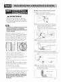
The door on your dryer can be installed to open
either to the left or the right. Follow these
instructions to reverse the direction in which your
door opens:
i I i
Door and latch should be aligned at the center
when closed.
12

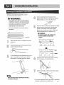
WARNING!
• Use a heavy metal vent.
• Do not use plastic or thin foil duct.
• Clean old ducts before installing this dryer.
• Failure to follow these instructions can
result in death or fire.
The exhaust must be vented tothe outside.
Improper taping and incorrect installation wil!
cause dryer malfunction,
In addition to the following warnings, please refer
to manual section on Exhaust Requirements and
Maintenance. Warning: The dryer must be vented
to the outdoors. Please follow the instructions (and
all others in this manual) very carefully. Failure to
follow these instructions can result in death or fire.
• Do not use plastic or thin foil duct.
• Use 4" (10.2 cm) diameter rigid or semi-rigid
metal duct (NOTE! Venting materials are not
supplied with the dryer, and you should obtain the
venting materials necessary for proper installation)
• Position the dryer such that the exhaust duct run is
as short as possible.
• Clean old ducts' before installing this' dryer
• The male end of each section of exhaust duct must
point away from the dryer.
• Use as few elbow joints as possible.
• Use duct tape on all duct joints.
• Insulate ductwork that runs through unheated
areas in order to reduce condensation and lint
build-up on pipe walls.
• PLEASE BE AWARE THAT FAILURE TO
EXHAUST THE DRYER CORRECTLY WiLL
VOiD THE DRYER'S WARRANTY.
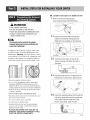
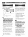
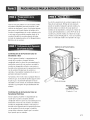
• ALTERNATE EXHAUST DIRECTIONS
]. Remove screw and exhaust duct.
(Use exhaust kit part #3911 EZ9131X.)
Detach and remove the knockout that
matches the desired venting direction
(Right side not available on Gas Dryers)
PORTION A _%
Knockout Q
\
2-2.
f
\
Connect a short piece of duct to the
blower housing and attach the duct to
the base.
3-1. Insert the male end of a 4" elbow into the
female end of a short duct. Tape the joint.
DUCT
TAPE
3-2. Insert this assembly elbow first through the
hole in the dryer and push the female end
of the elbow onto the male end of the
blower output shaft. Tape the joint.
13

s
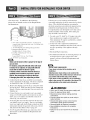
(Ga: dryer only). In addition to the following,
please refer to manual section on Gas Requirements
and Instructions.
1. New stainless steel flexible connector. Use this type of
connector only if allowed by local codes. Use Design AGA
Certified Connector.
2. 1/8" NPT Pipe Plug (tUr checking inlet gas pressure)
3. Equipment Shut-Off Valve
Installed within 6' (1.8 m) of dryer.
4. Iron Pipe. Shorter than 20' (6.1 m)
Use 3/8" pipe.
Longer than 20' (6.1 m) - Use 1/2" pipe.
5.3/8" N.P.T. Gas Connection.
Make sure the burner orifice is proper for the type of
For instance, using LPGwith LNGorifice will result
in death, fire or explosion. Or using LNGwith LPG
nozzle will not allow the burner to ignite.
If needed, orifice conversion should be done by a
qualified service technician and mark or put the
label of the current type of orifice onthe dryer.
If changing the orifice, also adjust the gas valve.
I. Confirln that the type of gas available in your laundry
room is appropriate IBr the dryer. The dryer is prepared
3 T_ o *
IBr Natural Gas with a, 18 NPT _as connection.
2. Remove the shipping cap fiom the gas connection at the
back of the dryer. Make sure that you don't damage the
threads of the gas connection pipe when you remove the
shipping cap.
3. Connect the dryer to your laundry room's gas supply
using a new flexible stainless steel connector (as noted
below, use a new stainless steel flexible connector if
allowed by your local codes).
4. Securely tighten all connections between the dryer and
your laundry room's gas supply. Turn on your laundry
room's gas supply and check all pipe connections (both
internal and external) for gas leaks with a non-corrosive
leak detection fluid. Refer to Part 7 (page 20)
5. For LP (Liquefied Petroleum) gas connection, refer to
this manual's section entitled Gas Requirements and
Instructions.
14
Following are several warnings and instructions
concerning makiug the electrical connection for electric
dryers. More detailed iutbrmatiou concerning the
electrical connection is provided in the manual section
entitled Electrical Requirements for Electric Dryer.
It is important that you thoroughly review that section
and the remainder of this manual, belBre taking any
steps to install or use this dryer.
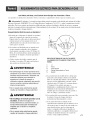
1. Use only a new UL listed No. 10 (copper wire only)
three conductor power supply cord kit rated 240
Volts (minimum) 30 Amperes and labeled as suitable
l_r use in a clothes dryer.
2. A four-wire cord is required for manufactured
(mobile) home installations and where local codes do
not allow grounding of this appliance through
neutral.
3. Electrical Plug Connections.
4. For additional instruction on connecting the dryer to
an electrical power source, please refer to this
manual's section on Electrical Requirements and
Electric Dryer.
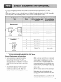
Burner input requirements
if yourhouse islocated at the elevationsup to
10,000 feet.
Adjustingburner input settingiSnot neededat this
elevationbecause AGAcertifies this dryerwill not have
any problemwith the BTUrating at this altitude.
if yourhouseisabove 10,ooo feet,you are requiredto
adjusta four percent (4%) reduction ofthe burner BTU
rating indicatedon the model/serial rating
WARNING!
• Use a new UL listed 30 amp power supply cord
• Use a UL approved strain relief
• Disconnect power before making electrical
connections
• Connect neutral wire (white or center wire) to
center terminal
• Ground wire (green or bare wire) must be
connected to green ground connector
• Securely tighten all electrical connections
• See installation instructions for complete
instructions
• Failure to do so can result in fire or electrical
shock

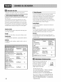
Prior to the first use of this appliance, use all-
purpose cleaning products or a solution of detergent
and watei; with damp cloth to remove from the
inside of the dryer drum/drying compartment any
dust or dirt that may have accumulated inside the
dryer. Plug-in your dryer after reviewing the
following parts on your dryer's Electrical
Requirements.
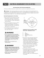
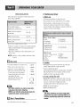
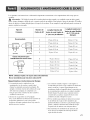
Effective dryer operation requires appropriate dryer
airflow. The adequacy of the airflow can be
measured by evaluating the static pressure.
Static pressure in the exhaust duct can be measured
with a manometer, placed on the exhaust duct
approximately 2 ft. (60.9 cm) from the dryer.
Static pressure in the exhaust duct should not
exceed 5/8 inches (1.5 cm). The dryer should be
checked while the dryer is running with no load.
Measuring Static pressure
Confirming Heat Source in Gas Dryers
Close the door to the dryer drum/drying
compartment and, after completing all steps in this
manual for proper installation of this dryer, start the
dryer on a heat setting. After the dryer starts, the
igniter will glow red and the main burner will
ignite.
Manometer
Warning: If all air is not purged from the gas line,
the gas igniter may go off before the gas and the
main burner have ignited. If this happens, the
igniter will re-attempt gas ignition alter
approximately two minutes.
Exhaust Duct
Confirming Heat Source in Electric Dryers
Close the door to the dryer drum/drying
compartment and, alter completing all steps in this
manual for proper installation of this dryer, start the
dryer on a heat setting. The exhaust air or the
exhaust pipe should be warm alter the dryer has
been operating for three minutes.
MAXIMUM STATIC
PRESSURE IN
WATER COLUMN
518 inches (1.5 cm)

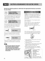
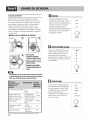
The following instructions are applicable to
installations of the dryer in a manufactured or
mobile home. Any installation in a manufactured or
mobile home must comply with the Manut:actured
Home Construction and Safety Standards Title 24
CFR, Part 32-80 or Standard CAN/CSAOZ240 MH
and local codes and ordinances. If you are
uncertain whether your proposed installation will
comply with these standards, please contact a
service and installation professional for assistance.
The following instructions apply to any installation
of the dryer in a manufactured or mobile home:
1) The electrical connection for an electric dryer
must be a 4-wire connection. More detailed
information concerning the electrical connection
is provided at the manual section entitled
Electrical Requirements for Electric Dryer
2) To reduce the risk of combustion and fire, the
dryer must be vented to the outside.
3)
4)
5)
6)
7)
8)
9)
Electric dryers may be vented to the outside
using the back, left, right, or bottom panel.
Gas dryers may be vented to the outside using the
back, left, or bottom panel. Gas dryers may not
be vented to the outside using the right side panel
because of the burner housing.
The dryer exhaust duct must be affixed securely
to the manufactured or mobile home structure,
the exhaust duct must be made of a material that
will resist fire and combustion, and it is
recommended that you use a rigid or flexible
metal pipe.
DO NOT connect the exhaust duct with any other
duct, vent, chimney, or other exhaust duct.
Make sure the dryer has adequate access to
outside fresh air to ensure proper operation. The
opening for outside fresh air must be at least 25
in_(163 cm:).
It is important that the clearance of the duct from
any combustible construction be at least 2 inches
(5 cm), and, when venting the dryer to the
outdoors, the dryer can be installed with a
clearance of 1 inch at the sides and back of the
dryer.
Please be aware that venting materials are not
supplied with the dryer. You should obtain the
venting materials necessary for proper
installation.
• DO NOT connect exhaust ducts with
metal screws or fasteners that extend
into the ducL
• Failure to do so can result in death,
explosion, or fire.
WARNING!
• DO NOT vent the exhaust duct under the
manufactured or mobile home.
• Failure to do so can result in death,
explosion, or fire.
16

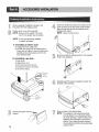
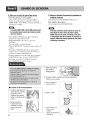
To ensure safe and secure installation, please
observe the instructions below.
WARNING!
• The weight of the dryer and the height of
installation makes the stacking procedure
too risky for one person. This procedure
should be performed by 2 or more
experienced service personnel.
• Incorrect installation can cause serious
accidents.
Fq_]_, ,_
6__ J
Stacking kit
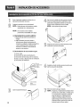
Place washer firmly on a stable, even and
solid floor.
Secure stacking kit side bracket to the
washer with a screw on the back of bracket.
Repeat Steps 2, 3, 4 for the other side.
Place the dryer on top of the washer by fitting
legs as shown in the picture. Avoid finger
injuries - be careful not to pinch fingers
between the washer and dryer. Slide dryer
slowly backwards to the stopper of kit.
• Donotstacka washeronthetopofthedryer.
• Incorrectinstallationcancauseserious
accidents.
Peel protective paper off the tape from the
stacking kit side bracket.
Fit the stacking kit side bracket firmly to the
side of top plate by attaching the double-
sided tape to top plate as picture shows.
Clean the surface before attaching the brackets
Insert the front rail. Push the front rail back
to the stoppers of side stacking kit.
Attach both sides of the front kit with screws.
_
• Do not use stacking kit with a gas dryer in potentially
unstable conditions like a mobile home.
17

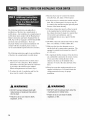
Remove pedestal, installation hardware, and
instructions from the shipping carton.
Position dryer on top of the pedestal.
NOTE : Because of the weight of the dryer
two or more people may be needed.
NOTE • If dryer was previously installed,
uninstall it as follows:
A. Uninstalling an electric dryer:
1) Unplug the power supply cord,
2) Pull the dryer away from the wall enough to
loosen the vent clamp. Loosen the clamp and
carefully remove the exhaust vent from the
dryer exhaust outlet.
B. Uninstalling a gas dryer:
1) Shut off gas.
2) Unplug power cord.
3) Disconnect gas line from dryer.
4) Pull away and loosen vent clamp.
5) Disconnect venting.
Attach the double-faced tape of the bracket to the
dryer as shown so the bent parts of the brackets
align with the edge and can be attached to the
pedestal with screws.
NOTE : Attach the bottom first.
I
Be sure to press the adhesive parts of the brackets
firmly to the appliance.
for dryer
for washer/
combo
combo
Install the eight (8) screws (supplied) to attach the
brackets to the pedestal.
18
Remove the paper from the
bracket.
Move the dryer to the desired place.
NOTE • The appliance and pedestal assembly
must be placed on a solid and level floor
for proper operation. Adjust the legs of the
appliance and pedestal by turning with a
wrench. Then, adjust the Iocknut toward
the pedestal while holding the pedestal leg
using a wrench.

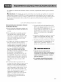
The following are additional instructions regarding electrical connections and requirements for electric dryers.
Warning: The wiring and grounding must conform to the latest edition of the National Electrical Code,
ANSI/NFPA 70 and all applicable local regulations. Please contact a qualified electrician to check your home's
wiring and fuses to ensure that your home has adequate electrical power to operate the dryer. Failure to do so can
result in fire or electrical shock.
120V/240V, 60 Hertz, 3-Wire Installation
Instructions for Grounding of your Electric
Dryer:
a) This dryer must be connected to a grounded
metal, permanent wiring system or an
equipment-grounding conductor must be run
with the circuit conductors and connected to the
equipment-grounding terminal or lead on the
dryer.
b) The dryer has its own terminal block that must
be connected to a separate 60 Hertz single
phase AC circuit, fused at 30 Amperes (the
circuit must be fused on both sides of the line).
ELECTRICAL SERVICE FOR THE DRYER
SHOULD BE OF MAXIMUM RATE
VOLTAGE LISTED ON THE NAMEPLATE.
DO NOT CONNECT DRYER TO 110, 115,
OR 120 VOLT CIRCUIT. Heating elements are
available for field installation in dryers which
are to be connected to electrical service of
different voltage than that listed on nameplate.
c) If branch circuit to dryer is fifteen feet (4.50 m)
or less in length, use U.L. (Underwriters
Laboratories) listed No. 10 A.W.G. wire (copper
wire only), or as required by local codes. If over
fifteen feet (4.50 m), use U.L. (Underwriters
Laboratories) listed No. 8 A.W.G. wire (copper
wire only), or as required by local codes. Allow
sufficient slack in wiring so dryer can be moved
from its normal location when necessary.
d) The power cord (pigtail) connection between
wall receptacle and dryer terminal block IS NOT
supplied with dryer. Type of pigtail and gauge of
wire must conform to local codes and with
instructions mentioned on the following pages.
e) The method of wiring the dryer is optional and
subject to local code requirements. Refer to
examples on next page.
f) You must select the method by which to wire
your dryer according to local code and ordinance
requirements. Sample methods are included in
the following pages.
19

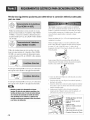
Review the following options to determine the appropriate electrical connection
for your home:
@
Use the instructions in this section if your home has
a 4-wire receptacle (NEMA type 14-30R) and you
will be using a UL listed, 1201240 volt minimum,
30 amp, dryer power supply cord.
Use the instructions in this section if your home has
a 3-wire receptacle (NEMA type 10-30R) and you
will be using a UL listed, 1201240 volt minimum,
30 amp, dryer power supply cord.
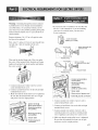
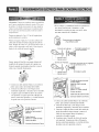
Warning : Grounding through the neutral conductor is
prohibited for (1) new branch-circuit installations, (2)
mobile homes, (3) recreational vehicles, and (4) areas
where local codes prohibit grounding through the
neutral conductor. Failure to do so can result in tire or
electrical shock.
Prepare nlininmm 5 ft (1.52 m) of length in order tk)r
dryer to be replaced.
First, peel 5 inches (12.7 cm) of covering material from
end. Strip 5 inches of ground wire insulation. After
cutting IV2inch (3.8 cm) from 3 other wires peel
insulation back 1 inch (2.5 cm). Make ends of 3 wires a
hook shape.
If this type is available at your home. you will be
connecting to a fused disconnect or circuit breaker
box.
If this type is available at your home. you will be
connecting to a fused disconnect or circuit breaker
box.
• Connect the power supply wire to the termina
block. Colored wire should be connected to
same color screw. Wire color indicated on
manual isconnected to the same color screw in
block. Otherwise,a short or excessive current
flow may result.
2O
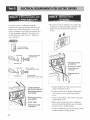
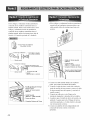
Then, put the hooked shape end of the wire under the
screw of the terminal block (hooked end facing to the
right) and pinch the hook together and screw tightly.
1. Connect neutral wire (white) of power cord to center
terminal block screw.
2. Connect red and black wires to the left and right
terminal block screws.
3. Connect ground wire (green) of power cord to external
ground screw and move neutral ground wire of
appliance and connect it to center screw.
4. Make sure that the strain relief screw is tightened.
Be sure that all terminal block nuts are on tight and
power cord is in right position.
Center terminal block
screw (silver)
Neutral grounding
wire (white)
Neutral wire
(white or center wire)
Strain relief
Green wire of power cord
External ground connector

Warning : Grounding through the neutral conductor
is prohibited for (1) new branch-circuit installations,
(2) mobile homes, (3) recreational vehicles, and (4)
areas where local codes prohibit grounding through the
neutral conductor. Failure to do so can result in fire or
electrical shock.
Prepare minimum 5 ft (1.52 m) of length in order
for dryer to be replaced.
First, strip 3 72 inches (8.9 cm) of outer sheath from
end and strip 1 inch of insulation from each
conductor. _
Then, put the hooked shape end of the wire under
the screw of the terminal block (hooked end facing
rightward) and pinch the hook together and tighten
the screw securely.
1. Connect neutral wire (white) of power cord to
center terminal block screw.
2. Connect red and black wires to the left and right
terminal block screws.
3. Make sure that the strain relief screw is tightened.
Be sure that all terminal block nuts are on tight
and power cord is in right position.
__ Neutral _rounding
_{_/_/;_ _ wire _wh re)
'_Z __,! Neutra, grounding
8_'"_% __ _ wire (wh,te)
_ LLL_Strainrelief
_" _\ I/_F- External ground
connector
• If your local codes or ordinances do not allow the
use of a 3-wire connection, or you are installing
your dryer in a mobile home, you must use a
4-wire connection.
( 4-wire receptacle
NEMAtype 14-30R)
-prona plua _ Spade terminals with
_pturned ends
d prong
_Neutral prong
4"prongplug _3/4 in. (1.9 cm)
pproved strain relief
d prong Ring terminals
rong
Center terminal block
screw (silver)
-- Neutral grounding
wire (white)
Neutral wire
(white or center wire)
Strain relief
Green wire of power cord
External ground connector
1. Connect neutral wire (white) of power cord to
center terminal block screw.
2. Connect red and black wires to the left and right
terminal block screws.
3. Connect ground wire (green) of power cord to
external ground screw and move neutral ground
wire of appliance and connect it to center screw.
4. Make sure that the strain relief screw is tightened.
Be sure that all terminal block nuts are on tight
and power cord is in right position.
21
Page is loading ...
Page is loading ...
Page is loading ...
Page is loading ...
Page is loading ...
Page is loading ...
Page is loading ...
Page is loading ...
Page is loading ...
Page is loading ...
Page is loading ...
Page is loading ...
Page is loading ...
Page is loading ...
Page is loading ...
Page is loading ...
Page is loading ...
Page is loading ...
Page is loading ...
Page is loading ...
Page is loading ...
Page is loading ...
Page is loading ...
Page is loading ...
Page is loading ...
Page is loading ...
Page is loading ...
Page is loading ...
Page is loading ...
Page is loading ...
Page is loading ...
Page is loading ...
Page is loading ...
Page is loading ...
Page is loading ...
Page is loading ...
Page is loading ...
Page is loading ...
Page is loading ...
Page is loading ...
Page is loading ...
Page is loading ...
Page is loading ...
Page is loading ...
Page is loading ...
Page is loading ...
Page is loading ...
Page is loading ...
Page is loading ...
Page is loading ...
Page is loading ...
-
 1
1
-
 2
2
-
 3
3
-
 4
4
-
 5
5
-
 6
6
-
 7
7
-
 8
8
-
 9
9
-
 10
10
-
 11
11
-
 12
12
-
 13
13
-
 14
14
-
 15
15
-
 16
16
-
 17
17
-
 18
18
-
 19
19
-
 20
20
-
 21
21
-
 22
22
-
 23
23
-
 24
24
-
 25
25
-
 26
26
-
 27
27
-
 28
28
-
 29
29
-
 30
30
-
 31
31
-
 32
32
-
 33
33
-
 34
34
-
 35
35
-
 36
36
-
 37
37
-
 38
38
-
 39
39
-
 40
40
-
 41
41
-
 42
42
-
 43
43
-
 44
44
-
 45
45
-
 46
46
-
 47
47
-
 48
48
-
 49
49
-
 50
50
-
 51
51
-
 52
52
-
 53
53
-
 54
54
-
 55
55
-
 56
56
-
 57
57
-
 58
58
-
 59
59
-
 60
60
-
 61
61
-
 62
62
-
 63
63
-
 64
64
-
 65
65
-
 66
66
-
 67
67
-
 68
68
-
 69
69
-
 70
70
-
 71
71
-
 72
72


LG DLG3744W Owner's manual
- Category
- Electric laundry dryers
- Type
- Owner's manual
Ask a question and I''ll find the answer in the document
Finding information in a document is now easier with AI
in other languages
Related papers
Other documents
-
GE DSXH47 User manual
-
Frigidaire FLCG7522AW User guide
-
-
Kenmore 41761722510 Installation guide
-
LG Electronics DLGX8101V Installation guide
-
-
Hotpoint NVL333EY0AA Owner's manual
-
-
-