
Not for
Reproduction
48kW & 62kW 3 Phase
Installation & Start-Up
Manual
Generator Systems
48000 & 62000Watt
3 Phase Generator System
Series 48000 & 62000
This generator is rated in accordance with UL (Underwriters Laboratories) 2200 (stationary engine generator assemblies) and CSA (Canadian Standards
Association) standard C22.2 No. 100-4 (motors and generators).
80014433 Rev A

Not for
Reproduction
2
Thank you for purchasing this quality-built GE generator. We are pleased that you’ve placed your confidence in the
GE brand. When operated and maintained according to the instructions in the operator’s manual, your generator will
provide many years of dependable service.
This manual contains safety information to make you aware of the hazards and risks associated with standby
generators and how to avoid them. This product is only for use as an optional generator system which provides an
alternate source of electric power and to serve loads such as heating, refrigeration systems, and communication
systems that, when stopped during any power outage, could cause discomfort or inconvenience. Only models equipped
with the MRS19 controller qualify for either an emergency standby or legally required standby system as defined by
NFPA 70 (NEC). For complete information on these types of installations, consult NFPA 70 and NFPA 110.
Save these original instructions for future reference.
This generator system requires professional installation before use. The installer should follow the instructions
completely.
Where to Find Us
You never have to look far to find support and service for your generator. Consult your Yellow Pages. There
are many GE authorized service dealers worldwide who provide quality service. You can also contact GE
Customer Service by phone at 888-575-8226 between 8:00 AM and 5:00 PM CT., or click on Find a Dealer at
www.standbygeneratorsystems.com, which provides a list of authorized dealers.
For Future Reference
Please fill out the information below and keep with your receipt to assist in unit identification for future purchase
issues.
Date of Purchase
Generator
Model Number
Model Revision
Serial Number

Not for
Reproduction
3 3
Table of Contents
Important Safety Instructions........................4
Installation ....................................7
Owner Responsibilities.........................................7
Installing Dealer/Contractor Responsibilities ........................7
Installation Checklist ..........................................8
Generator Placement ..........................................9
Exhaust Side of Generator ......................................9
Placement of Standby Generator to
REDUCE THE RISK OF CARBON MONOXIDE POISONING ............10
Other General Location Guidelines...............................11
Placement of Standby Generator to REDUCE THE RISK OF FIRE .......12
Concrete Slab (Required)
At the appropriate location, construct a concrete slab: . . . . . . . . . 14
Fuel Conversion .............................................18
Fuel Pressure ...............................................18
Power Loss ................................................18
Power Connections ..........................................19
Grounding the Generator ......................................22
Final Installation Considerations ................................22
Initial Start-up (No Load)......................................23
Controls ..................................... 24
Operation .................................... 24
Automatic Operation Sequence .................................24
Setting Exercise Timer ........................................24
Installation Inspection ........................................24

Not for
Reproduction
4
Save These Instructions
Important Safety Instructions
SAVE THESE INSTRUCTIONS - This manual contains
important instructions that should be followed during
installation and maintenance of the generator and
batteries.
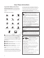
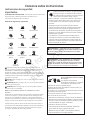
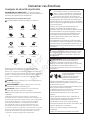
Safety Symbols and Meanings
The safety alert symbol indicates a potential personal
injury hazard. A signal word (DANGER, WARNING, or
CAUTION) is used with the alert symbol to designate a
degree or level of hazard seriousness. A safety symbol
may be used to represent the type of hazard. The signal
word NOTICE is used to address practices not related to
personal injury.
DANGER indicates a hazard which, if not avoided, will
result in death or serious injury.
WARNING indicates a hazard which, if not avoided,
could result in death or serious injury.
CAUTION indicates a hazard which, if not avoided,
could result in minor or moderate injury.
NOTICE addresses practices not related to personal
injury.
The manufacturer cannot possibly anticipate every
possible circumstance that might involve a hazard. The
warnings in this manual, and the tags and decals affixed
to the unit are, therefore, not all-inclusive. If you use a
procedure, work method or operating technique that
the manufacturer does not specifically recommend, you
must satisfy yourself that it is safe for you and others.
You must also make sure that the procedure, work
method or operating technique that you choose does not
render the generator system unsafe.
Fire
Toxic Fumes
Explosive Pressure
Rotating Fan Blade
Lift Hazard Read Manual
Exploding BatteryRotating Belt/Pulley
Chemical BurnAuto Start
Hot SurfaceRotating Parts
Electrical ShockExplosion
WARNING The engine exhaust from this product
contains chemicals known to the State of California
to cause cancer, birth defects, or other reproductive
harm.
WARNING Certain components in this product and
related accessories contain chemicals known to the
State of California to cause cancer, birth defects, or
other reproductive harm. Wash hands after handling.
WARNING Running engine gives off carbon
monoxide, an odorless, colorless, poison gas.
Breathing carbon monoxide could result
in death, serious injury, headache, fatigue,
dizziness, vomiting, confusion, seizures, nausea
or fainting.
• Operate this product ONLY outdoors in an area that
will not accumulate deadly exhaust gas.
• Keep exhaust gas away from any windows, doors,
ventailation intakes, soffit vents, crawl spaces, open
garage doors or other openings that can allow
exhaust gas to enter inside or be drawn into a
potentially occupied building or structure.
• Carbon monoxide detector(s) MUST be installed and
maintained indoors according to the manufacturer’s
instructions/recommendations. Smoke alarms cannot
detect carbon monoxide gas.
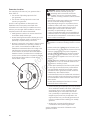
WARNING Storage batteries give off explosive
hydrogen gas during recharging.
Slightest spark will ignite
hydrogen and cause explosion,
resulting in death or serious
injury.
Battery electrolyte fluid contains acid and is
extremely caustic.
Contact with battery contents could cause severe
chemical burns.
A battery presents a risk of electrical shock and high
short circuit current.
• DO NOT dispose of battery in a fire. Recycle battery.
• DO NOT allow any open flame, spark, heat, or lit
cigarette during and for several minutes after
charging a battery.
• DO NOT open or mutilate the battery.
• Wear protective goggles, rubber apron, rubber boots
and rubber gloves.
• Remove watches, rings, or other metal objects.
• Use tools having insulated handles.

Not for
Reproduction
5
WARNING Generator produces hazardous
voltage.
Failure to properly ground generator could result
in electrocution.
Failure to isolate generator from utility power
could result in death or serious injury to electric
utility workers due to backfeed of electrical
energy.
• DO NOT touch bare wires or bare receptacles.
• DO NOT use generator with electrical cords which are
worn, frayed, bare or otherwise damaged.
• DO NOT handle generator or electrical cords while
standing in water, while barefoot, or while hands or
feet are wet.
• If you must work around a unit while it is operating,
stand on an insulated dry surface to reduce the risk of
a shock hazard.
• DO NOT allow unqualified persons or children to
operate or service generator.
• In case of an accident caused by electrical shock,
immediately shut down the source of electrical power
and contact the local authorities. Avoid direct contact
with the victim.
• Despite the safe design of the generator, operating
this equipment imprudently, neglecting its
maintenance or being careless could cause possible
injury or death.
• Remain alert at all times while working on this
equipment. Never work on the equipment when you
are physically or mentally fatigued.
• Before performing any maintenance on the
generator, disconnect the battery cable indicated by
a NEGATIVE, NEG or (-) first. When finished, reconnect
that cable last.
• After your system is installed, the generator may crank
and start without warning any time there is a power
failure. To prevent possible injury, always set the
generator’s system switch to OFF, remove the service
disconnect from the disconnect box AND remove the
15 Amp fuse BEFORE working on the equipment.
WARNING Propane and Natural Gas are extremely
flammable and explosive, which could
cause burns, fire or explosion resulting in
death or serious injury.
• Install the fuel supply system according to NFPA 37
and other applicable fuel-gas codes.
• Before placing the generator into service, the fuel
system lines must be properly purged and leak tested.
• NO leakage is permitted.
• DO NOT operate engine if smell of fuel is present or
other explosive conditions exist.
• DO NOT smoke around the generator. Wipe up any
oil spills immediately. Ensure that no combustible
materials are left in the generator compartment. Keep
the area near the generator clean and free of debris.
WARNING Exhaust heat/gases could ignite
combustibles or structures resulting in
death or serious injury.
Contact with muffler area could cause
burns resulting in serious injury.
• DO NOT touch hot parts and AVOID hot exhaust gases.
• Allow equipment to cool before touching.
• Exhaust outlet side of weatherproof enclosure must
have at least 5 ft. (1.5m) minimum clearance from any
structure, shrubs, trees or any kind of vegetation.
• Standby generator weatherproof enclosure must be
at least 5 ft. (1.5m) from windows, doors, any wall
opening, shrubs or vegetation over 12 inches (30.5 cm)
in height.
• Standby generator weatherproof enclosure must have
a minimum of 5 ft. (1.5 m) overhead clearance from
any structure, overhang, or trees.
• DO NOT place weatherproof enclosure under a deck
or other type of structure that may confine airflow.
• Use only flexible fuel line provided. Connect provided
fuel line to generator. DO NOT use with or substitute
any other flexible fuel line.
• Smoke detector(s) MUST be installed and maintained
indoors according to the manufacturer’s instructions/
recommendations. Carbon monoxide alarms cannot
detect smoke.
• Keep at least minimum distances shown in General
Location Guidelines to insure for proper generator
cooling and maintenance clearances.
WARNING Hazardous Voltage - Contact with power
lines could cause electric shock or burns,
resulting in death or serious injury.
Lifting Hazard / Heavy Object - Could
result in serious injury.
• If lifting or hoisting equipment is used, DO NOT contact
any power lines.
• DO NOT lift or move generator without assistance.

Not for
Reproduction
6
CAUTION Installing the 15A fuse could cause the
engine to start at any time without warning
resulting in minor or moderate injury.
• Observe that the 15 Amp fuse has been removed from
the control panel for shipping.
• DO NOT install this fuse until all plumbing and wiring
has been completed and inspected.
WARNING Moving parts could crush and cut.
Starter and other rotating parts
could entangle hands, hair, clothing,
or accessories resulting in serious
injury.
• NEVER operate generator without protective housings,
covers, or guards in place.
• DO NOT wear loose clothing, jewelry or anything that
could be caught in the starter or other rotating parts.
• Tie up long hair and remove jewelry.
• Before servicing, remove 15 Amp fuse from control
panel and disconnect Negative (NEG or -) battery
cable.
WARNING Hot pressurized coolant could cause
serious injury.
• DO NOT open radiator cap when hot.
• Before servicing, allow coolant to cool.
CAUTION Excessively high operating speeds could
result in minor injury and/or equipment damage.
Excessively low speeds impose a heavy load on
generator.
• DO NOT tamper with governed speed. Generator
supplies correct rated frequency and voltage when
running at governed speed.
• DO NOT modify generator in any way.
NOTICE Improper treatment of generator could
damage it and shorten its life.
• Use generator only for intended uses.
• If you have questions about intended use, contact
your authorized dealer.
• Operate generator only on level surfaces.
• Adequate, unobstructed flow of cooling and ventilating
air is critical for correct generator operation.
• The access panels/doors must be installed whenever
the unit is running.
• DO NOT expose generator to excessive moisture, dust,
dirt, or corrosive vapors.
• Remain alert at all times while working on this
equipment. Never work on the equipment when you
are physically or mentally fatigued.
• DO NOT start engine with air cleaner or air cleaner
cover removed.
• DO NOT insert any objects through cooling slots.
• DO NOT use the generator or any of its parts as a
step. Stepping on the unit could cause stress and
break parts. This may result in dangerous operating
conditions from leaking exhaust gases, fuel leakage,
oil leakage, etc.
• If connected devices overheat, turn them off and
disconnect them from generator.
• Shut off generator if:
-electrical output is lost;
-equipment sparks, smokes, or emits flames;
-unit vibrates excessively or makes unusal noises.
NOTICE Exceeding generators wattage/amperage
capacity could damage generator and/or electrical
devices connected to it.
• Start generator and let engine stabilize before
connecting electrical loads.

Not for
Reproduction
7
Installation
Equipment Description
This product is only for use as an optional generator
system which provides an alternate source of electric
power and to serve loads such as heating, refrigeration
systems, and communication systems that, when
stopped during any power outage, could cause
discomfort or inconvenience.
NOTICE Only models equipped with the MRS19 controller
qualify for either an emergency standby or legally
required standby system as defined by NFPA 70 (NEC).
For complete information on these types of installations,
consult NFPA 70 and NFPA 110.
• Emergency generator systems are intended to
automatically supply illumination, power, or both,
to designated areas and equipment in the event of
failure of the normal supply. Emergency systems
may also provide power for such functions as
ventilation where essential to maintain life, where
current interruption of the normal supply would
produce serious life safety or health hazards.
• Legally Required standby generator systems
are intended to automatically supply power to
selected loads in the event of failure of the normal
source which could create hazards or hamper
rescue or fire-fighting operations.
Every effort has been made to ensure that information
in this manual is accurate and current. However, we
reserve the right to change, alter, or otherwise improve
the product and this document at any time without prior
notice.
Only current licensed electrical and plumbing
professionals should attempt generator system
installations. Installations must strictly comply with
all applicable codes, industry standards laws and
regulations.
Owner Responsibilities
• Read and follow the instructions given in the
operator’s manual.
• Follow a regular schedule in maintaining, caring
for and using your generator, as specified in the
operator’s manual.
Installing Dealer/Contractor Responsibilities
• Read and observe the safety rules.
• Install only an UL approved transfer switch that is
compatible with the generator.
• Read and follow the instructions given in this
installation and start-up manual.
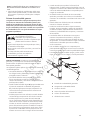
Unpacking Precautions
The unit is shipped ready for installation on a prepared
reinforced cement slab or engineered base. Avoid
damage from dropping, bumping, collision, etc. Store and
unpack carton with the proper side up, as noted on the
shipping carton.
Delivery Inspection
After removing the carton, carefully inspect the
generator for any damage that may have occurred
during shipment.
If loss or damage is noted at time of delivery, have the
person(s) making delivery note all damage on the freight
bill and affix his signature under the consignor’s memo of
loss or damage. If loss or damage is noted after delivery,
separate the damaged materials and contact the carrier
for claim procedures. Missing or damaged parts are
not warranted.
Shipment Contents
The generator system is supplied with:
• Fully-serviced coolant system
• Fully-serviced oil/lubricating system
• Flexible fuel hook-up hose
• Installation and Operator’s manual
• Spare access door keys
• Touch up paint
Not Supplied:
• Carbon monoxide detector(s)
• Smoke detector(s)
• Starting battery
• Reinforced concrete pad
• Connecting wire and conduit
• Fuel supply valves/plumbing
• Two 60” lengths of 2” Schedule 40 pipe (NOT
conduit)
• Crane, lifting straps, chains or cables
• Torque screwdriver, 5 to 50 inch-pound range
• Voltage/frequency meter
• Various special tools and equipment

Not for
Reproduction
8
Installation Checklist
Carbon Monoxide (CO) Detector
Carbon Monoxide (CO) detector installed and in working
order.
Smoke detector(s) installed and in working order.
Placement
Required permits have been obtained.
Generator placed in an area free from Carbon Monoxide
(CO) buildup. See Placement of Standby Generator to
Reduce the Risk of Carbon Monoxide Poisoning.
Generator placed in an area compliant to NFPA 37. See
Placement of Standby Generator to Reduce the Risk
of Fire.
Generator placed in an area free from water damage.
See Other General Location Guidelines.
Generator placed in an area free from utility and other
home systems. See Other General Location Guidelines.
Generator placed in a debris free zone. See Other
General Location Guidelines.
Generator placed on flat ground with provisions
for water drainage. See Other General Location
Guidelines.
Fuel
Generator is connected to fuel source with flexible fuel
line, has no fuel leaks and conforms to local codes. See
The Gaseous Fuel System.
Proper fuel pressure has been measured with all gas
appliances operating. See The Gaseous Fuel System.
Fuel system has been configured for the proper fuel
supply: Natural gas (NG) or liquefied petroleum ( LP). See
Fuel Conversion.
Fuel type: (circle one) NG LP
Fuel pipe size used: (circle one) 3/4” 1” 1-1/4” 1-1/2”
See NFPA 54, Chapter 6.
Fuel pressure at fuel inlet port with generator on and at
full load and all gas appliances turned on and operating
____________________.
Electrical
Generator neutral is connected to Automatic Transfer
Switch. See Generator AC Connection System.
Generator is grounded. See Grounding the Generator
and NFPA 70,NEC, Article 250.35B.
Generator is connected to the transfer switch with the
specified wiring. See Utility Circuit Connection and
Transfer Switch Communication.
Generator is connected to the transfer switch with
the specified wiring. #18AWG twisted pair wiring from
the generator control panel to the transfer switch is
installed in a separate conduit from high voltage wires
unless the insulation rating on all wiring is rated for
600V. See Transfer Switch Communication.
Dipswitches in most transfer switches must be set
to correspond to the wattage of the generator. See
Transfer Switch Operator/Installation Manual.
Operation
Cold weather kit is installed in temperatures below 30°F
(4°C). See Cold Weather Kit.
Correct battery type is installed and fully charged. See
Final Installation Considerations.
Generator engine oil level is at full mark. See Final
Installation Considerations.
Circuit breaker is in the ON position.
Utility was shut off to test the operation of generator
and transfer switch. Note any fault codes and make
corrections as required.
AC Voltage Output___________________________.
Frequency Output___________________________.
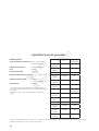
Owner Information
Name: ___________________________________________
Address: _________________________________________
Phone/e-mail: _____________________________________
Unit Information
Generator Model: __________________________________
Generator Serial Number: ___________________________
Installing Contractor Information
Name: ___________________________________________
Address: _________________________________________
Phone/FAX: _______________________________________
Electrician: _______________________________________
Signature: ________________________________________
Plumber: _________________________________________
Signature: _______________________________________
Inspector Information
Name: ___________________________________________
Address: _________________________________________
_________________________________________________
Title: _____________________________________________
Inspection Date: ___________________________________
This generator has been installed per the manufacturer’s
instructions:
Installing Contractor Signature: ___________________________
Date: _________________________________________________
Proper installation of the home generator requires the completion of the following tasks:

Not for
Reproduction
9
Before installing the generator, consult with the owner
and convey the following requirements, which must be
satisfied before the installation is complete.
There are two equally important safety concerns in
regards to carbon monoxide poisoning and fire. There
are also several general location guidelines that must
be met before the installation is considered complete.
Generator Placement
WARNING Running engine gives off carbon monoxide, an
odorless, colorless, poison gas.
Breathing carbon monoxide could result in death,
serious injury, headache, fatigue, dizziness, vomiting,
confusion, seizures, nausea or fainting.
• Operate this product ONLY outdoors in an area that will not
accumulate deadly exhaust gas.
• Keep exhaust gas away from any windows, doors,
ventailation intakes, soffit vents, crawl spaces, open garage
doors or other openings that can allow exhaust gas to
enter inside or be drawn into a potentially occupied building
or structure.
• Carbon monoxide detector(s) MUST be installed and
maintained indoors according to the manufacturer’s
instructions/recommendations. Smoke alarms cannot
detect carbon monoxide gas.
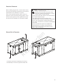
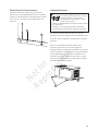
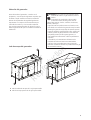
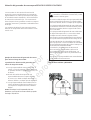
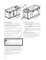
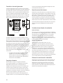
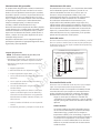
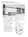
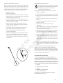
Exhaust Side of Generator
A Exhaust outlet side of weatherproof enclosure
B Weatherproof enclosure opposite exhaust side
A
A
B

Not for
Reproduction
10
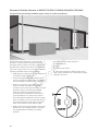
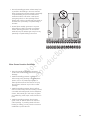
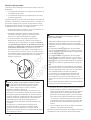
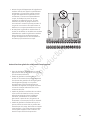
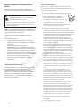
Placement of Standby Generator to REDUCE THE RISK OF CARBON MONOXIDE POISONING
The figure below demonstrates POTENTIAL points of entry for Carbon Monoxide Gas.
All fossil fuel burning equipment, such as standby
generators, contains carbon monoxide (CO) gas in
the engine exhaust. CO gas is odorless, colorless and
tasteless and is unlikely to be noticed until a person is
overcome. CO gas can kill you so it is required that the
following is included as part of the installation:
• Install generator outdoors in an area that will not
accumulate deadly exhaust gas.
• DO NOT install generator where exhaust gas
could accumulate and enter inside or be drawn
into a potentially occupied building or structure.
• By law it is required in many states to have a
Carbon Monoxide (CO) detector in operating
condition in homes and other structures occupied
by people. Carbon monoxide detector(s) (A)
MUST be installed and maintained indoors
according to the manufacturer’s instructions /
recommendations. A CO monitor is an electric
device that detects hazardous levels of CO. When
there is a buildup of CO, the monitor will alert the
occupants by flashing visual indicator light and
alarm. Smoke alarms cannot detect CO gas.
• Nearby structures may be exposed to the engine
exhaust from your standby generator and must
be considered when installing your standby
generator.
• Ensure exhaust gas is kept away from:
B overhead doors
C doors
D windows (not shown)
E other openings that can allow exhaust gas to
enter inside or be drawn into a potenially occupied
building or structure.
A
C
B B

Not for
Reproduction
11
• Direct the standby generator exhaust away from
or parallel to the building or structure. DO NOT
direct the generator exhaust towards a potentially
occupied building, structure, windows, doors,
ventilation intakes, soffit vents, crawl spaces,
open garage doors or other openings where
exhaust gas could accumulate and enter inside or
be drawn into a potentially occupied building or
structure.
• DO NOT place standby generator in any area
where leaves or debris normally accumulates.
Position standby generator in an area where
winds will carry the exhaust gas away from any
potentially occupied building or structure.
Other General Location Guidelines
• Place the standby generator in a prepared
location that is flat and has provisions for water
drainage.
• Install the standby generator in a location
where sump pump discharge, rain gutter down
spouts, roof run-off, landscape irrigation, or
water sprinklers will not flood the unit or spray
the enclosure and enter any air inlet or outlet
openings.
• Install the standby generator where it will not
affect or obstruct any services (including covered,
concealed and underground), such as telephone,
electric, fuel (natural gas / LPG vapor), irrigation,
air conditioning, cable, septic, sewer, well and so
forth.
• Install the standby generator where leaves,
grass, snow, etc will not obstruct air inlet and
outlet openings. If prevailing winds will cause
blowing or drifting, you may need to construct a
windbreak to protect the unit.

Not for
Reproduction
12
Placement of Standby Generator to REDUCE THE RISK OF FIRE
The National Fire Protection Association (NFPA)
standard NFPA 37 establishes criteria for minimizing
the hazard of fire during the installation and operation
of stationary combustion engines. NFPA 37 limits the
spacing of an enclosed generator from openings in
walls, structures and combustible materials outside the
enclosure.
The placement requirements provided are based on
compliance to NFPA 37 2010 section 4.1.4.
WARNING Exhaust heat/gases could ignite combustibles
or structures resulting in death or serious injury.
• Exhaust outlet side of weatherproof enclosure must have
at least 5 ft (1.5 m) minimum clearance from any structure,
shrubs, trees or any kind of vegetation.
• Standby generator weatherproof enclosure must be at least
5 ft (1.5 m) from windows, doors, any wall opening, shrubs
or vegetation over 12 inches (30.5 cm) in height.
• Standby generator weatherproof enclosure must have a
minimum of 5 feet (1.5 m) overhead clearance from any
structure, overhang or trees.
• DO NOT place weatherproof enclosure under a deck or
other type of structure that may confine airflow.
• USE ONLY flexible steel fuel line provided. Connect provided
fuel line to generator, DO NOT use with or substitute any
other flexible fuel line.
• Smoke detector(s) MUST be installed and maintained
indoors according to the manufacturer’s instructions/
recommendations. Carbon monoxide alarms cannot detect
smoke.
• DO NOT place weatherproof enclosure in manner other
than shown in illustrations.
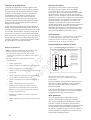
Examples of standby generator locations to reduce
the risk of fire:
Legend for Generator Locations to reduce the risk of
fire.
A Standby weatherproof enclosure must be at
least 5 ft (1.5 m) from windows, doors, any wall
opening, shrubs or vegetation over 12 inches (30.5
cm) in height.
B Exhaust outlet side of weatherproof enclosure
must have at least 5 ft (1.5 m) minimum clearance
from any structure, shrubs, trees or any kind of
vegetation.
C Standby weatherproof enclosure must have a
minimum of 5 feet (1.5 m) overhead clearance
from any structure, overhang or trees.
NOTICE DO NOT place weatherproof enclosure under
a deck or other type of covered structure that may
confine airflow.
Vertical and Horizontal Clearances
A
A
A
B
C

Not for
Reproduction
13
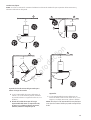
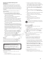
Legend for Generator Locations to reduce the risk of
fire.
A Standby weatherproof enclosure must be at
least 5 ft (1.5 m) from windows, doors, any wall
opening, shrubs or vegetation over 12 inches (30.5
cm) in height.
B Exhaust outlet side of weatherproof enclosure
must have at least 5 ft (1.5 m) minimum clearance
from any structure, shrubs, trees or any kind of
vegetation.
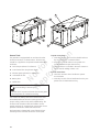
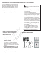
Typical Installations
NOTICE The figures below show the minimum installation distances allowed to structures and items listed in legend.
C Standby weatherproof enclosure must have a
minimum of 5 feet (1.5 m) overhead clearance from
any structure, overhang or trees.
NOTICE DO NOT place weatherproof enclosure under a
deck or other type of covered structure that may confine
airflow.
5 ft (1.5 m) min.
5 ft (1.5 m) min.
5 ft (1.5 m) min.
Standby
Standby
Standby
5 ft (1.5 m) min.
5 ft (1.5 m) min.
5 ft (1.5 m) min.
Exhaust
Exhaust
Exhaust
5 ft (1.5 m) min.
5 ft (1.5 m) min.
Standby
5 ft (1.5 m) min.
Exhaust
B
A
A
B
A
A
B
A
A
A
B

Not for
Reproduction
14
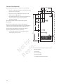
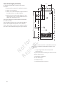
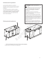
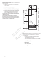
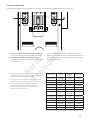
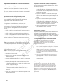
Concrete Slab (Required)
At the appropriate location, construct a concrete slab:
• 28 day compression strength of 3000 psi (200 MPa)
• Minimum 5” (13cm) thick
• Minimum 6” (15cm) wider than enclosure on all
sides (shown as D in figure)*
• Strengthen slab with No. 6 reinforcing bars (on 12”
(30.5cm) centers) or 8 ga. steel wire fabric
(6” (15cm) centers).
Avoid placing reinforcement in entrance stub-up area
(shown as B).
Attach unit to slab at four corner locations (A) with
minimum 5/16” diameter (8mm) (per local requirements)
masonry anchor bolts long enough to secure the unit.
The fuel inlet location (C),the concrete slab, and the
exhaust outlet (E) are shown for reference.
• The standby generator enclosure (F)measures
96” (243 cm) X 37” (94 cm).
A Holes located in base to anchor to pad
B Stub up Area
C Fuel Inlet
D Concrete slab
E Exhaust Outlet
F Standby Generator Enclosure
A
B
C
D
E
F
34-1/4”
87cm
7-1/2”
19cm
5”
12.7cm
14-3/4”
37.5cm
6”
15.2cm
51”
129.5cm
233.7cm

Not for
Reproduction
15
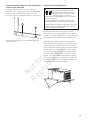
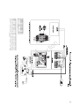
Electrical and Fuel Inlet Locations
A through-slab power cable stub-up is preferred. If
stub-up’s are not used, (B) indicates the recommended
location for punching holes for attaching power conduit.
The 1 inch N.P.T. fuel inlet connector (A) is shown for
reference.
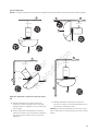
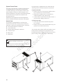
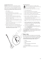
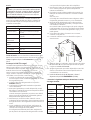
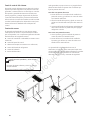
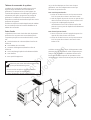
Lifting the Generator
The generator weighs approximately 2071 pounds
(939 kg). Proper tools, equipment and qualified personnel
should be used in all phases of handling and moving the
generator.
Remove circuit breaker box bottom plate prior to
positioning generator. Two 60” (1.5m) lengths of 2”
Schedule 40 pipe (C), supplied by the installer, are required
to lift the generator onto cement pad. Insert pipes through
the lifting holes (D) located near the unit’s base. Use a
spreader bar to ensure that the chains, straps or cables
DO NOT touch the generator’s roof. Retouch any chipped
paint with supplied touch-up paint.
A
B
WARNING Hazardous Voltage - Contact with power
lines could cause electric shock or burns,
resulting in death or serious injury.
Lifting Hazard / Heavy Object - Could
result in serious injury.
• If lifting or hoisting equipment is used, DO NOT contact
any power lines.
• DO NOT lift or move generator without assistance.
• Use lifting pipes as described in Lifting the Generator.
C
D

Not for
Reproduction
16
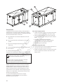
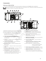
Access Ports
The generator is equipped with an enclosure that has
several access doors, as shown above. The doors are
named for a significant component located behind them,
as follows:
A - Fuel Inlet port (shown for reference)
B - Control Panel door (may be two doors)
C - Exhaust opening (shown for reference)
D - Coolant/Oil Fill door
E - Battery door
F - Muffler door
The Coolant Fill, Battery and Control Panel doors must
be installed whenever the unit is running to assure
proper cooling, reduce noise and for added safety. The
enclosure also includes muffler and radiator access
panels, used only for cleaning those components. Those
panels should remain closed at all other times.
Each generator is shipped with a set of identical keys.
These keys fit the locks that secure the access ports.
To open access door:
1. Insert key into lock of access door handle and turn
key one quarter turn counterclockwise.
2. Grasp door’s handle and turn one quarter turn
counterclockwise to open. Remove key.
3. Coolant Fill door is unlocked in the same manner. It
can be used for adding coolant or oil.
To close access door:
1. Close door and turn door’s handle one quarter
turn clockwise.
2. Insert key into lock of door handle and turn key one
quarter turn clockwise. Remove key.
WARNING Contact with muffler area could cause
burns resulting in serious injury.
• DO NOT touch hot parts and AVOID hot exhaust gases.
• Allow equipment to cool before touching.
B
A
C
D
E
F

Not for
Reproduction
17
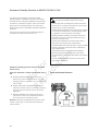
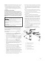
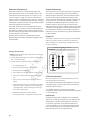
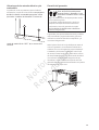
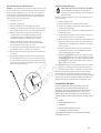
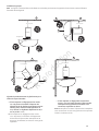
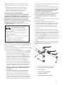
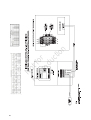
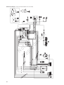
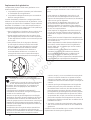
The Gaseous Fuel System
The information below is provided to assist gaseous
fuel system technicians in planning installations. In no
way should this information be interpreted to conflict
with applicable fuel gas codes. Consult with your local
fuel supplier or Fire Marshall if questions or problems
arise.
TO THE INSTALLER: Consult with the generator owner(s)
and convey any technical considerations that might
affect their installation plans before applying these
general guidelines.
The following general rules apply to gaseous fuel
system piping:
• The piping should be of a material that conforms
to federal and local codes, rigidly mounted and
protected against vibration.
• Piping should be protected from physical damage
where it passes through flower beds, shrub beds,
and other cultivated areas where damage could
occur.
• Install the flexible, gaseous hose (B) (supplied)
between the generator fuel inlet port (A) and rigid
piping to prevent thermal expansion or contraction
from causing excessive stress on the piping
material.
• A union (C) or flanged connection shall be provided
downstream to permit removal of controls.
• A manometer port should be provided (D). A
digital manometer, P/N 19495, is available at your
GE service center. When the initial test runs are
completed, the manometer is removed and the port
is plugged. The manometer port permits temporary
installation of a manometer to ensure that the
engine receives the correct fuel pressure to operate
efficiently throughout its operating range.
• Where the formation of hydrates or ice is known to
occur, piping should be protected against freezing.
The termination of hard piping should include a
sediment trap (E) where condensate is not likely to
freeze.
• A minimum of one accessible, approved manual
shutoff valve (F) shall be installed in the fuel supply
line within 6 ft (180 cm) of the generator.
• A manual fuel shut-off valve located in the interior
of the building.
• Where local conditions include earthquake,
tornado, unstable ground, or flood hazards, special
consideration shall be given to increase strength
and flexibility of piping supports and connections.
• Piping must be of the correct size to maintain the
required supply pressures and volume flow under
varying generator load conditions with all gas
appliances connected to the fuel system turned on
and operating.
• Use a pipe sealant or joint compound approved for
use with NG/LPG on all threaded fittings to reduce
the possibility of leakage.
• Installed piping must be properly purged and
leak tested, in accordance with applicable codes
and standards.
A Generator Fuel Inlet
B Flexible Fuel Hose
C Union Fitting
D Manometer Test Port
E Sediment Trap
F Manual Shut-off Valve
NOTICE The supplied flexible gaseous pipe is not to be
installed underground or in contact with the ground.
• The entire flexible gaseous pipe must be visible
for periodic inspection and must not be concealed
within nor contact nor run through any wall, floor, or
partition.
WARNING Propane
and Natural Gas are extremely
flammable and explosive, which could
cause burns, fire or explosion resulting in
death or serious injury.
• LP gas is heavier than air and will settle in low areas.
• Natural gas is lighter than air and will collect in
high areas.
• The slightest spark could ignite these fuels and cause
an explosion.
• DO NOT light a cigarette or smoke.
A
B
C
D
F
E

Not for
Reproduction
18
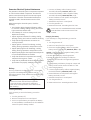
Fuel Pipe Sizing
There are numerous on-line or otherwise-published
references for fuel pipe sizing. For example, NFPA 54
- National Fuel Gas Code, 2006 (Item #: 320-6031-06)
is a common resource. The installer should consider
the specific gravity of gas, compensate for a nominal
amount of restriction from bends and fittings, and refer
to federal and local codes for guidance.
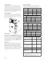
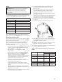
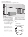
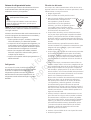
Fuel Conversion
The unit is shipped from the factory calibrated for NG
operation. To convert the engine from NG to LP vapor,
locate the fuel selector switch (A) and move the selector
switch to either LP or NG.
Fuel Pressure
Both LP vapor and natural gas fuel supply pressure at
the generator’s fuel inlet port should be between 7 to 11
inches (18 to 28 cm) of water (in. W.C.) at full load with
all gas appliances turned on and operating. Maximimum
pressure drop from static (engine not running) to full load
is 0.5 in. W.C. Maximum pressure with engine OFF at No
Load is 13.85 in. W.C.
Power Loss
Air density is less at high altitudes, resulting in less
available engine power. Specifically, engine power will
decrease 3% for each 1,000 feet (300 m) above sea
level and 1% for each 10° F (5.6°C) above 77°F (25°C).
Generators located in these conditions, that use power
management technology must have their transfer switch
programmed appropriately for this power decrease.
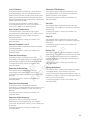
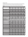
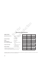
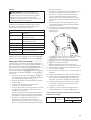
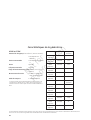
Fuel Consumption
Estimated fuel supply requirements at half and full load
for natural gas and LP vapor fuels are shown here.
Physical Properties LP Vapor Natural
Gas
Normal Atmospheric
State
Gas Gas
Boiling Point (in °F):
Initial
End
-44
-44
-259
-259
Heating Value:
BTU per gallon (Net LHV*)
BTU per gallon (gross**)
Cubic feet (gas)
83,340
91,547
2,500
63,310
1,000
Density*** 36.39 57.75
Weight† 4.24 2.65
Octane Number:
Research
Motor
110+
97
110+
* LHV (Low Heat Value) is the more realistic rating.
** Gross heat value does not consider heat lost in the form of
water during combustion.
*** Density is given in “Cubic Feet of Gas per Gallon of Liquid”.
† Weight is given in “Pounds per Gallon of Liquid”.
48kW LP Vapor Fuel Consumption
Full Load 1/2 Load Exercise
BTU/hr 708000 493500 247500
CF/ph 283 197 99
m³/ph 8.0 5.6 2.8
GAL/hr 7.9 5.5 2.8
48kW Natural Gas Fuel Consumption
Full Load 1/2 Load Exercise
BTU/hr 662400 464400 244800
CF/ph 662 464 245
m³/ph 18.8 13.2 6.9
A
62kW LP Vapor Fuel Consumption
Full Load 1/2 Load Exercise
BTU/hr 800300 581550 247050
ft³/hr 320 233 99
m³/hr 9.1 6.6 2.8
Gal/hr 8.9 6.5 2.8
55kW Natural Gas Fuel Consumption
Full Load 1/2 Load Exercise
BTU/hr 681500 512040 240840
ft³/hr 682 512 241
m³/hr 19.3 14.5 6.8

Not for
Reproduction
19
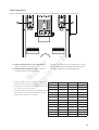
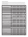
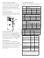
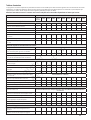
Series 48000* Voltage Rated Amps Wire Size
3 Phase Wye
120/208 167 3/0
3 Phase Wye
139/240 144 2/0
3 Phase Delta
120/240 144 2/0
3 Phase Wye
240/416 83 3 AWG
3 Phase Wye
277/480 72 4 AWG
3 Phase Wye
346/600 58 4 AWG
Series 62000* Voltage Rated Amps Wire Size
3 Phase Wye
120/208 215 250kcmil
3 Phase Wye
139/240 186 4/0
3 Phase Delta
120/240 186 4/0
3 Phase Wye
240/416 108 1 AWG
3 Phase Wye
277/480 93 2 AWG
3 Phase Wye
346/600 75 4 AWG
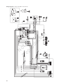
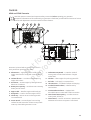
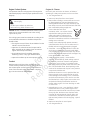
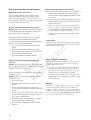
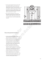
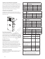
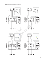
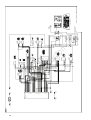
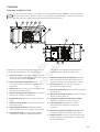
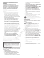
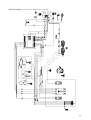
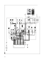
A - Power Connection (Line 1, Line 2 and Line 3) —
Power connection to transfer switch.
B - Neutral and/or Ground Connection — Connect
to transfer switch neutral and ground.
For system connections such as remote start, e-stops
and controller inputs and outputs, please refer to the
connection diagrams on the following pages.
Power Connections
Compare this illustration with your generator to familiarize yourself with the location of these connections.
• For power output connection, use 300 volt, 167 °F-194 °F
(75 °C-90 °C) wire. See chart on right for proper wire size.
• For Utility Circuit connection use #14 AWG minimum 300
volt, 167 °F-194 °F (75 °C-90 °C) wire.
• For transfer switch communication use #18 AWG twisted
pair conductors, no greater than 200 ft (60 m) in length,
300 volt, 167 °F-194 °F (75 °C-90 °C) wire.
*Refer to Generator Data Tag to determine series of generator.
A
B
B
Page is loading ...
Page is loading ...

Not for
Reproduction
22
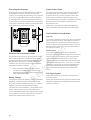
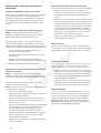
Grounding the Generator
Ground the generator per applicable codes, standards
and regulations. There are two generator GND lug
locations. The one inside the generator junction box next
to the circuit breaker (A) primary lug and should suffice
for most applications. The second generator GND lug is
located on the frame below the generator circuit breaker
cover and should ONLY be used for a ground rod located
at the generator, if required by local codes.
Shutdown Alarm Detection System
The generator may have to run for long periods of time
with no operator present. For that reason, the system
is equipped with sensors that automatically shut down
the generator in the event of potentially damaging
conditions, such as low oil pressure, high temperature,
over speed, and other conditions.
• Refer to Shutdown Alarm Detection System in
the operator’s manual and the Control Panel
Application Guide supplied with this generator for
more detailed information.
Battery Charger
This unit does not include a battery charger as standard
equipment. Optional chargers are available through
GE. Power for battery chargers is by way of a customer
supplied connection consistent with the charger
manufacturers recommendations. Consult NFPA 110 for
specific charger requirements in those applications.
It is recommended that the power supply for the charger
is on a separate circuit than the power for any heaters
(engine block heater, battery warmers, etc.).
System Control Panel
The system control panel is a printed circuit board that
is integrated with the control panel of the generator.
It contains all the logic circuits, operator controls, and
system displays necessary to operate, program, and
protect the generator. The system control panel interprets
and monitors electrical inputs from related circuits
throughout the unit.
Please refer to the supplied Control Panel Application
Guide for detailed information about the control panel.
Final Installation Considerations
Engine Oil
This engine is shipped from the factory pre-run and filled
with non-synthetic oil (API SL 10W-30W). This allows for
system operation in a wide range of temperature and
climate conditions. Before starting the engine, check oil
level and ensure that engine is serviced as described in
the operator’s manual.
Coolant System
This engine is shipped from the factory filled with a
50-50 mix of automotive (Ethylene glycol) anti-freeze and
water. This will provide optimum year round protection
against freezing, boiling and corrosion. The coolant
system incorporates an water heater that operates with
a fixed thermostat set at 100°F - 120°F (39°C - 49°C) AND
utility power is present at the customer supplied power
connection for the heater. Before starting the engine,
check coolant level as described in the Maintenance
section
Fuel Supply System
Ensure that all fuel pipe connections are tight, secure
and without leaks.
Ensure that all gas line shutoff valves are OPEN and that
adequate fuel pressure is available whenever automatic
operation is desired.
A
Page is loading ...
Page is loading ...
Page is loading ...
Page is loading ...
Page is loading ...
Page is loading ...
Page is loading ...
Page is loading ...
Page is loading ...
Page is loading ...
Page is loading ...
Page is loading ...
Page is loading ...
Page is loading ...
Page is loading ...
Page is loading ...
Page is loading ...
Page is loading ...
Page is loading ...
Page is loading ...
Page is loading ...
Page is loading ...
Page is loading ...
Page is loading ...
Page is loading ...
Page is loading ...
Page is loading ...
Page is loading ...
Page is loading ...
Page is loading ...
Page is loading ...
Page is loading ...
Page is loading ...
Page is loading ...
Page is loading ...
Page is loading ...
Page is loading ...
Page is loading ...
Page is loading ...
Page is loading ...
Page is loading ...
Page is loading ...
Page is loading ...
Page is loading ...
Page is loading ...
Page is loading ...
Page is loading ...
Page is loading ...
Page is loading ...
Page is loading ...
Page is loading ...
Page is loading ...
Page is loading ...
Page is loading ...
Page is loading ...
Page is loading ...
Page is loading ...
Page is loading ...
Page is loading ...
Page is loading ...
Page is loading ...
Page is loading ...
Page is loading ...
Page is loading ...
Page is loading ...
Page is loading ...
Page is loading ...
Page is loading ...
Page is loading ...
Page is loading ...
Page is loading ...
Page is loading ...
Page is loading ...
Page is loading ...
Page is loading ...
Page is loading ...
Page is loading ...
Page is loading ...
Page is loading ...
Page is loading ...
Page is loading ...
Page is loading ...
Page is loading ...
Page is loading ...
Page is loading ...
Page is loading ...
Page is loading ...
Page is loading ...
Page is loading ...
Page is loading ...
Page is loading ...
Page is loading ...
Page is loading ...
Page is loading ...
Page is loading ...
Page is loading ...
Page is loading ...
Page is loading ...
Page is loading ...
Page is loading ...
Page is loading ...
Page is loading ...
Page is loading ...
Page is loading ...
Page is loading ...
Page is loading ...
Page is loading ...
Page is loading ...
Page is loading ...
Page is loading ...
Page is loading ...
Page is loading ...
Page is loading ...
Page is loading ...
Page is loading ...
Page is loading ...
Page is loading ...
Page is loading ...
Page is loading ...
Page is loading ...
Page is loading ...
Page is loading ...
-
 1
1
-
 2
2
-
 3
3
-
 4
4
-
 5
5
-
 6
6
-
 7
7
-
 8
8
-
 9
9
-
 10
10
-
 11
11
-
 12
12
-
 13
13
-
 14
14
-
 15
15
-
 16
16
-
 17
17
-
 18
18
-
 19
19
-
 20
20
-
 21
21
-
 22
22
-
 23
23
-
 24
24
-
 25
25
-
 26
26
-
 27
27
-
 28
28
-
 29
29
-
 30
30
-
 31
31
-
 32
32
-
 33
33
-
 34
34
-
 35
35
-
 36
36
-
 37
37
-
 38
38
-
 39
39
-
 40
40
-
 41
41
-
 42
42
-
 43
43
-
 44
44
-
 45
45
-
 46
46
-
 47
47
-
 48
48
-
 49
49
-
 50
50
-
 51
51
-
 52
52
-
 53
53
-
 54
54
-
 55
55
-
 56
56
-
 57
57
-
 58
58
-
 59
59
-
 60
60
-
 61
61
-
 62
62
-
 63
63
-
 64
64
-
 65
65
-
 66
66
-
 67
67
-
 68
68
-
 69
69
-
 70
70
-
 71
71
-
 72
72
-
 73
73
-
 74
74
-
 75
75
-
 76
76
-
 77
77
-
 78
78
-
 79
79
-
 80
80
-
 81
81
-
 82
82
-
 83
83
-
 84
84
-
 85
85
-
 86
86
-
 87
87
-
 88
88
-
 89
89
-
 90
90
-
 91
91
-
 92
92
-
 93
93
-
 94
94
-
 95
95
-
 96
96
-
 97
97
-
 98
98
-
 99
99
-
 100
100
-
 101
101
-
 102
102
-
 103
103
-
 104
104
-
 105
105
-
 106
106
-
 107
107
-
 108
108
-
 109
109
-
 110
110
-
 111
111
-
 112
112
-
 113
113
-
 114
114
-
 115
115
-
 116
116
-
 117
117
-
 118
118
-
 119
119
-
 120
120
-
 121
121
-
 122
122
-
 123
123
-
 124
124
-
 125
125
-
 126
126
-
 127
127
-
 128
128
-
 129
129
-
 130
130
-
 131
131
-
 132
132
-
 133
133
-
 134
134
-
 135
135
-
 136
136
-
 137
137
-
 138
138
-
 139
139
-
 140
140
-
 141
141
-
 142
142
-
 143
143
-
 144
144


Ask a question and I''ll find the answer in the document
Finding information in a document is now easier with AI
in other languages
- français: Simplicity 076041-02 Manuel utilisateur
- español: Simplicity 076041-02 Manual de usuario