
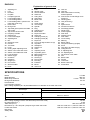
Flip over saw Instruction manual
Mesin gergaji lipat Petunjuk penggunaan
Máy ca góc a nng Tài liu hng dn
LF1000
GB
VI
TH
ID

2
1 006027 2 006028
3 006029 4 006030
5 006031 6 006073
7 001540 8 006033
2
1
3
4
5
6
7
8
10
9
11
13
12
14
15
16
17

3
9 006034 10 006035
11 006036 12 006037
13 006038 14 006039
15 006040 16 006041
18
14
20
19
21
19
21
22
23
24
25
26
21
19
28
27
22
29

4
17 012645
18 006043
19 006044
30 31
34
33
32
34
33
32

5
20 012641 21 006046
22 006047 23 006048
24 012642 25 012643
26 006051 27 012644
35
30
36
21
37
7
38
38 7
40
39
40
38
35
41
38
44
42
43
35
10
45
5-6mm
10
38
10
46
35

6
28 006053 29 006054
30 006055 31 006056
32 006057 33 006058
34 006059 35 006060
47
48
49
50
51
51
47
52
38
53
54
51
47
ABC
38
D
51
47
55
49
50
A
B
56
51
47
57
58
38
51
59
60
61

7
36 006061
37 005560
38 006062 39 006063
40 006064 41 006065
62
63
63
64
62
65
66
67
18
68
14
18
14

8
42 006066 43 006067
44 006068
45 006072 46 006069
21
A
B
15
16
10
10
45
10
45
10
(a)
(b)
(f)
(e)
(c)
(d)
18
29
B
A

9
47 006070 48 006071
49 006074
50 006075
69
21
70
71
29
B
A
10
45
10
45
10
10
(a)
(b)
(e)
(c)
(d)

10
51 006078 52 006079
53 001844
54 006080
55 006081 56 006082
72
72
73
74
14
75
74
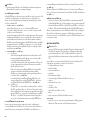
6mm
50mm
130mm
300mm
50mm
120mm
300mm
76
130mm
77
9.5mm
50mm
78
8mm
100mm
19
9.5mm
76
460mm
19mm
120mm
40mm
140mm

11
57 006083 58 006084
59 006085
60 006086
61 006088 62 006087
79
80
81
80
82 83
84
85
61
60
86

12
63 006089 64 006090
65 006091 66 006092
67 006093 68 001819
69 006094 70 001145
29
87
14
38
88
89
90
88
38
91
92
93
94
20
95

13
71 006095
96
97

14
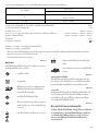
ENGLISH
Explanation of general view
SPECIFICATIONS
Model LF1000
Blade diameter 260 mm
Blade body thickness 1.8 mm - 2.0 mm
Riving knife thickness 2.2 mm
Hole diameter
For European countries 30 mm
Max. Cutting capacities (H x W) with blade 260 mm in diameter in the miter saw mode
Max. Cutting capacities at 90°in the table saw (bench saw mode) 70 mm
No load speed (min
-1
) 2,700
Table size (W x L) 500 mm x 555 mm
Dimensions (L x W x H1(note 1)/H2(note 2)) at miter saw mode 660 mm x 650 mm x 1,220 mm / 800 mm
in table saw mode 660 mm x 650 mm x 1,060 mm / 845 mm
Net weight 36 kg
Safety class /II
1. Adjusting nut
2. Foot
3. Hex Bolt
4. Fix plate
5. U-shaped grooves
6. Lower blade guard A
7. Lower blade guard B
8. Lower blade guard C (used in the
miter saw mode only)
9. Push button
10. Riving knife
11. Top blade guard (used in the table
saw mode)
12. Top surface of turn base
13. Periphery of blade
14. Guide fence
15. Lower limit stopper
16. Adjusting bolt
17. Nut
18. Clamping screw
19. Handle
20. Turn table
21. Lever
22. Cutting depth adjusting knob
23. Switch in the miter saw mode
24. Switch in the table saw mode
25. Lock-off button
26. Switch trigger
27. On button
28. Off button
29. Stopper pin
30. Hex wrench
31. Wrench holder
32. Hook
33. Feet
34. Stopper hook
35. Hex socket bolt
36. Shaft lock
37. Lifting lever
38. Saw blade
39. Blade case
40. Arrow
41. Outer flange
42. Inner flange
43. Spindle
44. Ring
45. Clamping nut
46. Blade width
47. Rip fence holder
48. Guide rail
49. Clamping screw (A)
50. Clamping screw (B)
51. Rip fence
52. Line to be aligned with:Line (A)
53. Top table
54. Workpiece
55. Square nut
56. Scale
57. Adjusting screw
58. Top blade guard
59. Miter gauge fence
60. Miter gauge
61. Groove(s)
62. Dust nozzle
63. Dust bag
64. Fastener
65. Elbow
66. Vise knob
67. Vise rod
68. Vise arm
69. Saw head locked in the fully
lowered position
70. Area of lever for hand/finger to be
placed on
71. Hooking parts
72. Vise (accessory)
73. Vise
74. Spacer block
75. Aluminum extrusion
76. Face/edge parallel
77. Wood screw
78. Guide together
79. Push stick
80. Auxiliary fence
81. Push block
82. Cross cutting
83. Mitering
84. Bevel cutting
85. Compound mitering (angles)
86. Knob
87. Tool part to be held carrying
88. Triangular rule
89. 0° adjusting bolt
90. 45° adjusting bolt
91. Top surface of turn table
92. Arm
93. Bevel scale
94. Pointer
95. Limit mark
96. Brush holder cap
97. Screwdriver
Bevel angle
Miter angle
0°
0°
20 mm x 180 mm
68 mm x 155 mm
45° (left) 50 mm x 150 mm

15
Note1 H1: Height up to the tool head
Note2 H2: Height up to the table
•Due to our continuing program of research and development, the specifications herein are subject to change without
notice.
• Specifications may differ from country to country.
•Weight according to EPTA-Procedure 01/2003
END213-5
Symbols
The following show the symbols used for the equipment.
Be sure that you understand their meaning before use.
............... Read instruction manual.
............... DOUBLE INSULATION
........ To avoid injury from flying debris, keep
holding the saw head down, after making
cuts, until the blade has come to a
complete stop.
................ Do not place hand or fingers close to the
blade.
................ For your safety, remove the chips, small
pieces, etc. from the table top before
operation.
................ Unplug the tool before turning it over
around the axis.
.............. Position hands properly when carrying.
..... Do not lift up the top end of the rip fence
when installing or removing it.
ENE061-1
Intended use
The tool is intended for accurate straight and miter cutting
in wood. The tool can be used both in miter saw mode
and in table saw mode by turning over the table around its
axis.
ENF002-2
Power supply
The tool should be connected only to a power supply of
the same voltage as indicated on the nameplate, and can
only be operated on single-phase AC supply. They are
double-insulated and can, therefore, also be used from
sockets without earth wire.
ENA001-2
SAFETY INSTRUCTIONS
WARNING! When using electric tools, basic safety
precautions, including the following, should always
be followed to reduce the risk of fire, electric shock
and personal injury. Read all these instructions
before operating this product and save these
instructions.
For safe operations:
1. Keep work area clean.
Cluttered areas and benches invite injuries.
2. Consider work area environment.
Do not expose power tools to rain. Do not use power
tools in damp or wet locations. Keep work area well lit.
Do not use power tools where there is risk to cause
fire or explosion.
3. Guard against electric shock.
Avoid body contact with earthed or grounded surfaces
(e.g. pipes, radiators, ranges, refrigerators).
4. Keep children away.
Do not let visitors touch the tool or extension cord. All
visitors should be kept away from work area.
5. Store idle tools.
When not in use, tools should be stored in a dry, high
or locked up place, out of reach of children.
6. Do not force the tool.
It will do the job better and safer at the rate for which it
was intended.
7. Use the right tool.
Do not force small tools or attachments to do the job of
a heavy duty tool. Do not use tools for purposes not
intended; for example, do not use circular saws to cut
tree limbs or logs.
8. Dress properly.
Do not wear loose clothing or jewellery, they can be
caught in moving parts. Rubber gloves and non-skid
footwear are recommended when working outdoors.
Wear protecting hair covering to contain long hair.
9. Use safety glasses and hearing protection.
Also use face or dust mask if the cutting operation is
dusty.
10. Connect dust extraction equipment.
If devices are provided for the connection of dust
extraction and collection facilities ensure these are
connected and properly used.
11. Do not abuse the cord.
Never carry the tool by the cord or yank it to
disconnect it from the socket. Keep the cord away
from heat, oil and sharp edges.
12. Secure work.
Use clamps or a vice to hold the work. It is safer than
using your hand and it frees both hands to operate the
tool.
13. Do not overreach.
Keep proper footing and balance at all times.
14. Maintain tools with care.
Keep cutting tools sharp and clean for better and safer
performance. Follow instructions for lubrication and
changing accessories. Inspect tool cord periodically
and if damaged have it repaired by an authorized

16
service facility. Inspect extension cords periodically
and replace, if damaged. Keep handles dry, clean and
free from oil and grease.
15. Disconnect tools.
When not in use, before servicing and when changing
accessories such as blades, bits and cutters.
16. Remove adjusting keys and wrenches.
Form the habit of checking to see that keys and
adjusting wrenches are removed from the tool before
turning it on.
17. Avoid unintentional starting.
Do not carry a plugged-in tool with a finger on the
switch. Ensure switch is off when plugging in.
18. Use outdoor extension leads.
When tool is used outdoors, use only extension cords
intended for outdoor use.
19. Stay alert.
Watch what you are doing. Use common sense. Do
not operate tool when you are tired.
20. Check damaged parts.
Before further use of the tool, a guard or other part
that is damaged should be carefully checked to
determine that it will operate properly and perform its
intended function. Check for alignment of moving
parts, free running of moving parts, breakage of parts,
mounting and any other conditions that may affect its
operation. A guard or other part that is damaged
should be properly repaired or replaced by an
authorized service center unless otherwise indicated
in this instruction manual. Have defective switches
replaced by an authorized service facility. Do not use
the tool if the switch does not turn it on and off.
21. Warning.
The use of any accessory or attachment, other than
those recommended in this instruction manual or the
catalog, may present a risk of personal injury.
22. Have your tool repaired by a qualified person.
This electric tool is in accordance with the relevant
safety requirements. Repairs should only be carried
out by qualified persons using original spare parts,
otherwise this may result in considerable danger to
the user.
ENB094-3
ADDITIONAL SAFETY RULES
FOR TOOL
FOR BOTH MITER SAW MODE AND TABLE SAW
(BENCH SAW) MODE:
1. Wear eye and hearing protection. Other suitable
personal protective equipment should be worn.
2. NEVER wear gloves during operation except for
replacing saw blades or handling rough material
before operation.
3. Keep the floor area around the tool level well
maintained and free of loose materials e.g. chips
and cut-offs.
4. Do not operate saw without guards and riving
knife in place. Check blade guards for proper
closing before each use. Do not operate saw if
blade guards do not move freely and close
instantly. Never clamp or tie the blade guards into
the open position. Any irregular operation of the
blade guards should be corrected immediately.
5. Clean and be careful not to damage the spindle,
flanges (especially the installing surface) and
fixing bolt before or when installing the blade.
Damage to these parts could result in blade
breakage. Poor installation may cause vibration/
wobbling or slippage of the blade. Use only
flanges specified for this tool.
6. Check the blade carefully for cracks or damage
before operation. Do not use saw blade which are
damaged or deformed.
7. Use only saw blades recommended by the
manufacturer and which conform to EN847-1, and
observe that the riving knife must not be thicker
than the width of the cut by the saw blade and not
thinner than the body of the blade.
8. Always use accessories recommended in this
manual. Use of improper accessories such as
abrasive cut-off wheels may cause an injury.
9. Select the correct saw blade for the material to be
cut.
10. Do not use saw blades manufactured from high
speed steel.
11. To reduce the emitted noise, always be sure that
the blade is sharp and clean.
12. Use correctly sharpened saw blades. Observe the
maximum speed marked on the saw blade.
13. Do not cut metal objects such as nails and screws.
Inspect for and remove all nails, screws and other
foreign material from the workpiece before
operation.
14. Knock out any loose knots from workpiece
BEFORE beginning to cut.
15. Do not use the tool in the presence of flammable
liquids or gases.
16. For your safety, remove the chips, small pieces,
etc. from the work area and table top before
plugging the tool and starting operation.
17. The operator is adequately trained in the use,
adjustment and operation of the tool.
18. Keep hands and make your bystander and
yourself position out of path of and not in line with
saw blade. Avoid contact with any coasting blade.
It can still cause severe injury and never reach
around saw blade.
19. Be alert at all times, especially during repetitive,
monotonous operations. Do not be lulled into a
false sense of security. Blades are extremely
unforgiving.
20. Make sure the shaft lock is released before the
switch is turned on.
21. Before using the tool on an actual workpiece, let it
run for a while. Watch for vibration or wobbling
that could indicate poor installation or a poorly
balanced blade.
22. Wait until the blade attains full speed before
cutting.
23. The tool should not be used for slotting,
rabbetting or grooving.
24. Refrain from removing any cut-offs or other parts
of the workpiece from the cutting area whilst the
tool is running and the saw head is not in the rest
position.

17
25. Stop operation immediately if you notice anything
abnormal.
26. Turn off tool and wait for saw blade to stop before
moving workpiece or changing settings.
27. Unplug tool before changing blade, servicing or
not in use.
28. Some dust created from operation contains
chemicals known to cause cancer, birth defects or
other reproductive harm. Some examples of these
chemicals are:
lead from lead-based-painted material and,
arsenic and chromium from chemically-treated
lumber.
Your risk from these exposures varies, depending
on how often you do this type of work. To reduce
your exposure to these chemicals: work in a well
ventilated area and work with approved safety
equipment, such as those dust masks that are
specially designed to filter out microscopic
particles.
29. Connect the tool to a dust collecting device when
sawing.
30. Make sure that the table is securely fixed with the
lever after turning it over.
WHEN USING IN MITER SAW MODE:
31. Do not use the saw to cut other than wood,
aluminum or similar materials.
32. Do not perform operation freehand when cutting
workpiece in an area close to saw blade. The
workpiece must be secured firmly against the turn
table and guide fence during all operations.
33. Make sure that the turn table is properly secured
so it will not move during operation.
34. Make sure that the arm is securely fixed when
beveling. Tighten the lever clockwise to fix the
arm.
35. Make sure the blade does not contact the turn
table in the lowest position and is not contacting
the workpiece before the switch is turned on.
36. Hold the handle firmly. Be aware that the saw
moves up or down slightly during start-up and
stopping.
WHEN USING IN THE TABLE SAW (BENCH SAW)
MODE:
37. Do not perform any operation freehand. Freehand
means using your hands to support or guide the
workpiece, in lieu of a rip fence.
38. Make sure that the turn table is fixed securely.
39. Make sure that the arm is securely fixed in the
working position. Tighten the lever clockwise to
fix the arm.
40. Use a push stick or a push block to avoid working
with the hands and fingers close to the saw blade.
41. Make sure the blade is not contacting the riving
knife or workpiece before the switch is turned on.
42. Always store the push-stick when it is not in use.
43. Pay particular attention to instructions for
reducing risk of KICKBACK. KICKBACK is a
sudden reaction to a pinched, bound or
misaligned saw blade. KICKBACK causes the
ejection of the workpiece from the tool back
towards the operator. KICKBACKS CAN LEAD TO
SERIOUS PERSONAL INJURY. Avoid KICKBACKS
by keeping the blade sharp, by keeping the rip
fence parallel to the blade, by keeping the riving
knife and blade guard in place and operating
properly, by not releasing the workpiece until you
have pushed it all the way past the blade, and by
not ripping a workpiece that is twisted or warped
or does not have a straight edge to guide along
the fence.
44. Avoid abrupt, fast feeding. Feed as slowly as
possible when cutting hard workpieces. Do not
bend or twist workpiece while feeding. If you stall
or jam the blade in the workpiece, turn the tool off
immediately. Unplug the tool. Then clear the jam.
45. Before turning over the tool, always make sure
that the stopper pin has securely locked the tool
head in the lowest position
SAVE THESE INSTRUCTIONS.
INSTALLATION
CAUTION:
•Keep the floor area around the tool level well
maintained and free of loose materials such as chips
and cut-offs.
Bench mounting
For the fully-extended feet set up as the high table
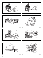
When the tool cannot be set up stable, turn the adjusting
nut at the foot of the tool for proper stability. Turn
counterclockwise in top viewing to make the foot shorter
and clockwise in top viewing to make it longer. After
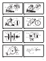
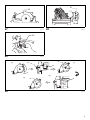
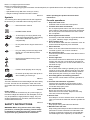
adjustment, make sure that the tool keep stable. (Fig. 1)
Install the fix plates with its angled end pointing outwards
onto three feet of the tool with hex bolts. And secure the
tool to the stable and level surface using bolt holes
provided in the fix plates with three bolts. (Fig. 2)
For the folded feet set up as the low table (Fig. 3)
When the tool is ready in the foot-folded position, secure
the tool by using U-shaped grooves shown in the figure.
FUNCTIONAL DESCRIPTION
CAUTION:
•Always be sure that the tool is switched off and
unplugged before adjusting or checking function on the
tool.
Blade guard (Fig. 4, Fig. 5 & Fig. 6)
CAUTION:
•Make sure that the handle cannot be lowered without
pushing the lever nearby the handle to the left.
•Make sure that the lower blade guards A dose not open
unless the lever near the handle is pushed at the
topmost position of the handle.
•Make sure that the lower blade guard C is installed
before using in miter saw mode.
When lowering the handle while pushing the lever to the
left, the lower blade guard A rises automatically. The
lower blade guard B rises as it contacts a workpiece. The
lower blade guards are spring loaded so it returns to its
original position when the cut is completed and the handle

18
is raised. The top blade guard falls flat on the table
surface after workpiece has passed under it. NEVER
DEFEAT OR REMOVE THE LOWER BLADE GUARDS,
THE SPRING WHICH ATTACHES TO THE LOWER
BLADE GUARD, OR THE TOP BLADE GUARD except
for the note below.
In the interest of your personal safety, always maintain
each blade guard in good condition. Any irregular
operation of the guards should be corrected immediately.
Check to assure spring loaded return action of the lower
blade guards. NEVER USE THE TOOL IF THE LOWER
BLADE GUARD, SPRING OR THE TOP BLADE GUARD
ARE DAMAGED, FAULTY OR REMOVED except for the
note below. DOING SO IS HIGHLY DANGEROUS AND
CAN CAUSE SERIOUS PERSONAL INJURY.
NOTE:
•There are the following exceptions for removal of
guards. Only when using in the table saw mode, the
lower blade guard C is removed. Only when using in
the miter saw mode, the top blade guard is removed.
If any of these see-through blade guards becomes dirty,
or sawdust adheres to it in such a way that the blade is no
longer easily visible, unplug the saw and clean the guards
carefully with a damp cloth. Do not use solvents or any
petroleum-based cleaners on the plastic guard.
If the lower blade guard A is especially dirty and vision
through the guard is impaired, proceed as follows. Raise
the handle fully. Remove the saw blade (Refer to the
section “Installing or removing saw blade”). Raise the
lower blade guard A while pushing the lever to the left.
With the lower blade guard A so positioned, cleaning can
be more completely and efficiently accomplished. When
cleaning is complete, reverse procedure above and
secure bolt.
In the same case for the top blade guard as above stated,
push in the button at its front to the surface top and
remove the top blade guard. After cleaning, always
reinstall it securely.
If any of these blade guards becomes discolored through
age or UV light exposure, contact a Makita service center
for a new guard. DO NOT DEFEAT OR REMOVE
GUARDS.
Maintaining maximum cutting capacity
This tool is factory adjusted to provide the maximum
cutting capacity for a 260 mm saw blade.
When installing a new blade, always check the lower limit
position of the blade and if necessary, adjust it as follows:
CAUTION:
•When making this adjustment, unplug the tool.
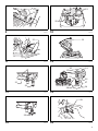
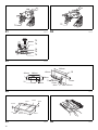
First, unplug the tool. Lower the handle completely. Use
the wrench to turn the adjusting bolt until the periphery of
the blade extends slightly below the top surface of the turn
table at the point where the front face of the guide fence
meets the top surface of the turn table. (Fig. 7)
With the tool unplugged, rotate the blade by hand while
holding the handle all the way down to be sure that the
blade does not contact any part of the lower base. Re-
adjust slightly, if necessary.
CAUTION:
• After installing a new blade, always be sure that the
blade does not contact any part of the lower base when
the handle is lowered completely. Always do this with
the tool unplugged.
This tool can be used with or without the lower limit by
shifting the lower limit stopper as shown in the figure.
To use the tool without the lower limit, turn the stopper end
counterclockwise. Use in this position is proper to cut a
wide and thin workpiece. (Fig. 8)
To use the tool with the lower limit, move the stopper end
clockwise. Use in this position is proper to cut a thick
workpiece.
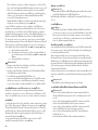
Adjusting the miter angle (Fig. 9 & Fig. 10)
Loosen the clamping screw on the guide fence by turning
counterclockwise. Turn the turn table by handle. When
you have moved the handle to the position where the
pointer points to the desired angle on the miter scale,
securely tighten the clamping screw clockwise.
CAUTION:
•When turning the turn table, be sure to raise the handle
fully.
• After changing the miter angle, always secure the turn
table by tightening the clamping screw firmly.
Adjusting the bevel angle
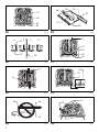
In the miter saw mode (Fig. 11 & Fig. 12)
To adjust the bevel angle, loosen the lever at the rear of
the tool counterclockwise.
Push the handle to the left to tilt the saw blade until the
pointer points to the desired angle on the bevel scale.
Then tighten the lever clockwise firmly to secure the arm.
CAUTION:
•When tilting the saw blade, be sure to raise the handle
fully.
• After changing the bevel angle, always secure the arm
by tightening the lever clockwise.
In the table saw mode (Fig. 13)
To adjust the bevel angle, loosen the lever under the table
at the front of the tool counterclockwise.
Move the depth adjusting knob to the left to tilt the saw
blade until the pointer points to the desired angle on the
bevel scale. Then tighten the lever clockwise firmly to
secure the arm.
Switch action (Fig. 14)
Switch for the miter saw mode
CAUTION:
• Before plugging in the tool, always check to see that
the switch lever actuates properly and returns to the
“OFF” position when released.
•When not using the tool, remove the lock-off button and
store it in a secure place. This prevents unauthorized
operation.
•Do not pull the switch lever hard without pressing in the
lock-off button. This can cause switch breakage.
To prevent the switch lever from being accidentally pulled,
a lock-off button is provided. To start the tool, push the
lock lever to the left, press in the lock-off button and then
pull the switch lever. Release the switch lever to stop.

19
Switch for the table saw mode
CAUTION:
•Before operation, make sure that the tool is turned on
and off.
To start the tool, press the ON ( I ) button. To stop it, press
the OFF ( O ) button.
Adjusting the depth of cut (Fig. 15 &
Fig. 16)
The depth of cut can be adjusted by turning the cutting
depth adjusting knob. Turn the cutting depth adjusting
knob clockwise to raise the blade or counterclockwise to
lower it.
WARNING:
•Use a shallow depth setting when cutting thin materials
in order to obtain a cleaner cut.
CAUTION:
•The stopper pin cannot be turned with the tool head at
fully lowered position. At this time, turn the knob
counterclockwise slightly and the stopper pin can be
released.
Overload protector
• Tools for 200V or higher power supply only. Refer to
nameplate on the tool for the rated voltage.
•When the load on the tool exceeds admissible levels,
power to the motor is reduced to protect the motor from
overheating. When the load returns to admissible
levels, the tool will operate as normal.
ASSEMBLY
CAUTION:
• Always be sure that the tool is switched off and
unplugged before carrying out any work on the tool.
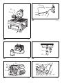
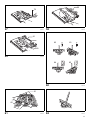
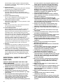
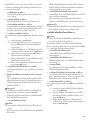
Hex wrench storage (Fig. 17)
The hex wrench is stored as shown in the figure. When
using the hex wrench, pull it out of the wrench holder.
After using the hex wrench, return it to the wrench holder.
Table height two-way set up
The table height can be set up in two ways, high or low
table.
WARNING:
• Before falling down the tool backwards, always set the
tool in the miter saw mode and lock the tool head in the
lowest position.
1. High table set up (Fig. 18)
To set up t he to ol wi th hi gh table, proceed as follows.
(1) Fall down the tool carefully BACKWARDS
without fail while holding it with both hands.
(2) Turn the hook in the direction of arrow in the
figure to unbundle the feet. Open the table feet
on one side and push the bottom bar of the feet
forward fully to be locked by itself. Take the
same procedure for the feet on the opposite
side. Make sure that the feet at both sides are
completely locked.
WARNING:
•Make sure that the stopper hooks are perfectly
positioned in the groove of the bracket.
(3) Return the tool to the upright position.
2. Low table set up (Fig. 19)
The feet can be folded as shown in the figure. To fold
down the tool, do as follows.
(1) Fall down the tool carefully BACKWARDS
without fail while holding it with both hands.
(2) Pull up first the stopper at the joint of left feet
toward yourself to unlock it
(3) Take the same steps for the opposite feet as
above.
(4) Use a hook to bundle these feet.
(5) Return the tool to the upright position.
Installing or removing saw blade
CAUTION:
•Always be sure that the tool is switched off and
unplugged before installing or removing the blade.
•Use only the Makita hex wrench provided to install or
remove the blade. Failure to do so may result in
overtightening or insufficient tightening of the hex
socket bolt. This could cause an injury.
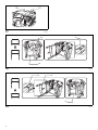
Move up the handle in the fully raised position.
Press the shaft lock to lock the spindle, use the hex
wrench to loosen the hex socket bolt clockwise. (Fig. 20)
Raise the blade guard A with its lifting lever while pushing
the lever nearby the handle to the left. With the blade
guard A raised, remove the hex socket bolt, outer flange
and blade. (Fig. 21)
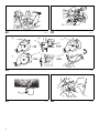
To install the blade, mount it carefully onto the spindle,
making sure that the direction of the arrow on the surface
of the blade matches the direction of the arrow on the
blade case. Install the outer flange and hex socket bolt,
and then use the hex wrench to tighten the hex socket bolt
(left-handed) securely counterclockwise while pressing
the shaft lock. (Fig. 22 & Fig. 23)
NOTE:
•When installing a saw blade, be sure to insert it
between the blade guard B at first and then raise it so
that the blade is finally placed in the blade guard B.
For all countries other than European countries
(Fig. 24)
CAUTION:
•The silver ring 25.4 mm in outer diameter is factory-
installed onto the spindle. The black ring 25 mm in
outer diameter is included as standard equipment.
Before mounting the blade onto the spindle, always be
sure that the correct ring for the arbor hole of the blade
you intend to use is installed onto the spindle.
For European countries
CAUTION:
•The ring 30 mm in outer diameter is factory-installed
between the inner and outer flanges.
Return the lower blade guard A to its original position.
Lower the handle to make sure that the lower blade
guards move properly. Make sure shaft lock has released
spindle before making cut.

20
Adjusting riving knife (Fig. 25, Fig. 26 &
Fig. 27)
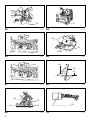
There must be a clearance of about 5 - 6 mm between the
riving knife and the blade teeth when pushing the riving
knife toward the blade fully. Adjust the riving knife
accordingly by first loosening clamping nut by hand
counterclockwise and then loosening hex socket bolt
counterclockwise with the hex wrench, and measuring the
distance. After adjustment, securely tighten the hex
socket bolt and then the clamping nut clockwise. Always
check to see that the riving knife is secured and that the
top blade guard works smoothly before cutting.
The riving knife has been installed before shipment from
the factory so that the blade and riving knife are in a
straight line after your simple set-up. Refer to the section
titled “Repositioning riving knife” for the set-up.
CAUTION:
•If the blade and riving knife are not aligned properly, a
dangerous pinching condition may result during
operation. Make sure the riving knife is positioned
between both outer ends of the blade teeth when
viewing from the top. You could suffer serious personal
injury while using the tool without a properly aligned
riving knife. If they are not aligned for any reasons,
always have Makita authorized service center repair it.
•When adjusting the riving knife clearance from the
blade teeth, always loosen the hex socket bolt only
after loosening the clamping nut.
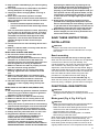
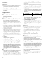
Installing and adjusting rip fence
1. Install the rip fence on the table so that the rip fence
holder engages with the guide rail. Tighten the
clamping screw (B) of the rip fence firmly clockwise.
2. Loosen the clamping screw (A). (Fig. 28)
3. Slide the rip fence and secure it so that the far end
from you of the rip fence is aligned with the point at
which the front edge of saw blade just appears from
top surface of the workpiece. The purpose of this
adjustment is to reduce risk of kick-back toward
operator that cut piece from the workpiece is pinched
between the saw blade and rip fence and finally
pushed out toward operator. The line (A) varies by
thickness of workpiece or the table level. Adjust the
position of the rip fence according to the thickness of
the workpiece.
After adjusting the rip fence, tighten the clamping
screw (A) firmly. (Fig. 29)
NOTE:
•There are four patterns to position the rip fence as
shown in the figure. Rip fence has two slits on its sides,
one slit with an elevated fringe nearby on the same
side and the other without it. Use the surface of rip
fence with this fringe facing the workpiece only when
cutting off into a piece of a thin workpiece.
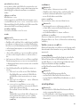
NOTE:
•To change the rip fence pattern, remove the rip fence
from the rip fence holder by loosening the clamping
screw (A) and change the facing of the rip fence to the
rip fence holder so that the rip fence faces the rip fence
holder according to your work as shown in the figure.
Insert the square nut on the rip fence holder into the
back end of either slit of the rip fence so that they fit as
shown in the figure.
To cha nge from t he patt ern A or B to the pattern C or D,
or in adverse case, remove the square nut and
clamping screw (A) from the rip fence holder, then
position the clamping screw (A) and square nut on the
opposite position of the rip fence holder compared to
the original position Tighten the clamping screw (A)
securely after inserting the square nut of the rip fence
holder into the rip fence slit.
Insert the square nut on the rip fence holder into the
back end of either slit of the rip fence so that they fit as
shown in the figure. (Fig. 30)
The rip fence is factory adjusted so that it is parallel to the
blade surface. Make sure that it is parallel. To check to be
sure that the rip fence is parallel with the blade, adjust the
blade height with the cutting depth adjusting knob so that
the blade appears at the topmost position from the table.
Mark one of the blade teeth with a crayon. Measure the
distance (A) and (B) between the rip fence and blade.
Take both measurements using the tooth marked with the
crayon. These two measurements should be identical If
the rip fence is not parallel with the blade, proceed as
follows: (Fig. 31 & Fig. 32)
(1) Turn the adjusting screw counterclockwise.
(2) Shift the front edge of the rip fence slightly to
right or left until it becomes parallel with the
blade. (Fig. 33 & Fig. 34)
(3) Tighten the adjusting screw on the rip fence
firmly.
CAUTION:
• Be sure to adjust the rip fence so that it is parallel with
the blade, or a dangerous kickback condition may
occur.
• Be sure to adjust the rip fence so that it does not
contact the top blade guard or saw blade.
• Do not relocate or carry the tool by rip fence.
•Raising the installed rip fence or exerting a force on it
to the right and left with your hand grabbing its top end
may damage it and impair its function.
Installing and adjusting miter gauge
(Fig. 35)
Install the miter gauge by inserting its shaft into one of two
grooves in the table from the front. Miter gauge fence that
is also used as rip fence can be installed on the miter
gauge according to your work.
Dust bag
The use of the dust bag makes cutting operations clean
and dust collection easy. To attach the dust bag, fit it onto
the dust nozzle. (Fig. 36)
When the dust bag is about half full, remove the dust bag
from the tool and pull the fastener out. Empty the dust bag
of its contents, tapping it lightly so as to remove particles
adhering to the insides which might hamper further
collection. (Fig. 37)
If you connect a vacuum cleaner to your saw, more
efficient and cleaner operations can be performed.
(Fig. 38)
Page is loading ...
Page is loading ...
Page is loading ...
Page is loading ...
Page is loading ...
Page is loading ...
Page is loading ...
Page is loading ...
Page is loading ...
Page is loading ...
Page is loading ...
Page is loading ...
Page is loading ...
Page is loading ...
Page is loading ...
Page is loading ...
Page is loading ...
Page is loading ...
Page is loading ...
Page is loading ...
Page is loading ...
Page is loading ...
Page is loading ...
Page is loading ...
Page is loading ...
Page is loading ...
Page is loading ...
Page is loading ...
Page is loading ...
Page is loading ...
Page is loading ...
Page is loading ...
Page is loading ...
Page is loading ...
Page is loading ...
Page is loading ...
Page is loading ...
Page is loading ...
Page is loading ...
Page is loading ...
Page is loading ...
Page is loading ...
Page is loading ...
Page is loading ...
-
 1
1
-
 2
2
-
 3
3
-
 4
4
-
 5
5
-
 6
6
-
 7
7
-
 8
8
-
 9
9
-
 10
10
-
 11
11
-
 12
12
-
 13
13
-
 14
14
-
 15
15
-
 16
16
-
 17
17
-
 18
18
-
 19
19
-
 20
20
-
 21
21
-
 22
22
-
 23
23
-
 24
24
-
 25
25
-
 26
26
-
 27
27
-
 28
28
-
 29
29
-
 30
30
-
 31
31
-
 32
32
-
 33
33
-
 34
34
-
 35
35
-
 36
36
-
 37
37
-
 38
38
-
 39
39
-
 40
40
-
 41
41
-
 42
42
-
 43
43
-
 44
44
-
 45
45
-
 46
46
-
 47
47
-
 48
48
-
 49
49
-
 50
50
-
 51
51
-
 52
52
-
 53
53
-
 54
54
-
 55
55
-
 56
56
-
 57
57
-
 58
58
-
 59
59
-
 60
60
-
 61
61
-
 62
62
-
 63
63
-
 64
64


Ask a question and I''ll find the answer in the document
Finding information in a document is now easier with AI
Related papers
Other documents
-
Ryobi BT3100-1 User manual
-
-
Craftsman 315.22811 User manual
-
-
-
Porter-Cable PCB222TS User manual
-
Delta 36-725 T2 Owner's manual
-
-
-