Page is loading ...

Unity
™
-1.5 1.5 gpm (5.7 L/min) flow restrictor
-2.0 2.0 gpm (7.6 L/min) flow restrictor
-SS Slip spout on any tub/shower unit
-X Integral service stops
-CHKS Integral check stops
-IPS 1/2” female IPS connections
-REV Reverse coring for back to back
installations
-LP Loop handle
-QD Quick disconnect on hand shower units
-R White vinyl hose in place of metal hose
-OP 13” oval plate
-72 6’ hose in place of 5’ standard
-TRM Trim only, valve not included
-STN Satin Nickel finish
Model Numbers
Operation & Maintenance Manual
6603, 6604
Specification
Warranty
Limited Lifetime - to the original end purchaser in
consumer/residential installations.
5 Years - for industrial/commercial installations.
Refer to www.symmons.com/warranty for complete
warranty information.
Compliance
Certied by
CSA Group
Modifications
Note: Append appropriate -sufx to model number.
-ASME A112.18.1/CSA B125.1
-WaterSense 1.5 gpm (5.7 L/min)
2.0 gpm (7.6 L/min)
6603
Unity Hand Shower System
6604
Unity Tub/Hand Shower System
6603
Hand shower system powered by the Temptrol
®
Pressure Balancing valve. Features adjustable stop
screw to limit handle turn, wall cradle, in-line vacuum
breaker, 60” exible metal hose, 1 mode hand shower and
standard 2.5 gpm (9.5 L/min) ow restrictor. Components
made from metal and nonmetallic materials plated in
standard polished chrome nish.
6604
Tub/hand shower system powered by the Temptrol
®
Pressure Balancing valve. Features adjustable stop screw
to limit handle turn, wall cradle, diverter tub spout, in-line
vacuum breaker, 60” exible metal hose, 1 mode hand
shower and standard 2.5 gpm (9.5 L/min) ow restrictor.
Components made from metal and nonmetallic materials
plated in standard polished chrome nish.
For California Residents
WARNING: This product contains chemicals known to
the State of California to cause cancer, birth defects, or
other reproductive harm.

2
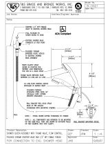
Dimensions
Notes:
1) All dimensions measured from nominal rough-in (see E as reference).
2) Dimensions subject to change without notice.
FLOORFLOOR
FF
BB
AA
DD
CC
II
KK
JJ
GG
HH
LL
EE
Measurements
A 3 1/2”, 89 mm
B
Male 1/2” NPT tting must be
recessed 1/4” from
nished wall
C
Shower Valve Hole Size
Min. Ø 3”, 76 mm
Max. Ø 4”, 102 mm
D 3 3/4”, 95 mm
E
Rough-in
2 3/8” ± 1/2”, 60 mm ± 13 mm
F
Ref. 32”, 813 mm
(6604)
Ref. 42”, 1067 mm
(6603)
G
Male 1/2” NPT tting must
protrude 4” from
nished wall
H 5 1/4”, 133 mm
I 2 1/8”, 54 mm
J Ø 6 3/8”, 162 mm
K 3 1/2”, 89 mm
L Ø 2 1/2”, 64 mm

3
Parts Breakdown
HOT
Water Supply
A
C
D
E
O
B
COLD
Water Supply
E
F
L
H
G
M
N
I
J
K
Notes:
1) Apply a bead of silicone around the perimeter of all shower trim
installed ush to the nished wall. Leave opening on bottom of
escutcheon for weep hole.
2) Apply plumber tape to all threaded connections.
*Note: Append -STN to part number for
Satin Nickel nish.
Replacement Parts
Item Description Part Number
A
B
Handle
Assembly
RTS-064*
C Dome Cover T-19*
D
E
F
Shower
Escutcheon Kit
6600-ESC*
G Hand Shower EF-100*
H
I
J
Wall Cradle
Assembly
EF-106*
K
L
Wall Ell EF-105*
M
N
In-line Vacuum
Breaker &
60” Hose
SP-4*
O Tub Spout 054*
Tools Required
Adjustable wrench
Allen wrench (1/8”)
Drill
Phillips head
screwdriver
Plumber tape
Silicone

4
1
2
F
E
2) Attach shower escutcheon (D) to
mounting plate (F).
1
D
F
1) Install mounting plate (F) to
shower valve. Secure with two
screws (E).
4) Install handle (A) to valve and
secure with set screw (B).
A
B
1
2
5) Install tub spout (O) to pipe tting.
Turn clockwise to secure.
Installation
Note:
For valve body installation, please
see valve body manual.
7) Place mounting plate
(J)
in po-
sition, mark and drill 3/16” holes
for tile anchors (J1), 5/16” holes
for drywall anchors (J2). Install
anchors.
2
3
1
J
J2
4
J1
J2
J3
3) Install dome cover (C) to valve by
turning clockwise.
1
2
C
6) Install wall ell
(K)
to pipe tting.
Tighten set screw (L) to secure.
L
K
1
2
8) Remove cover of hand shower
cradle
(H)
. Install cradle and
mounting plate
(J)
. Secure with
three screws
(I)
. Replace cover
on hand shower cradle.
4
3
2
1
H
I
J
Note: Tabs should snap into place.
Note: Handle should be facing the
6 o’clock position.
1
O
2
Note: For dry wall 1/2” thick or less,
insert anchor tool (J3) into drywall
anchor (J2) to secure behind wall
prior to installing wall cradle.

Symmons Industries, Inc. ■ 31 Brooks Drive ■ Braintree, MA 02184 ■ Phone: (800) 796-6667 ■ Fax: (800) 961-9621
Copyright © 2016 Symmons Industries, Inc. ■ www.symmons.com ■ [email protected] ■ ZV-3139 REV B ■ 012516
1) Turn shower handle counterclock-
wise approximately 1/4 turn to put
valve in cold position.
Operation (Temperature Control)
2) Turn shower handle counterclock-
wise approximately 1/2 turn to put
valve in warm position.
3) Turn shower handle counterclock-
wise approximately 3/4 turn to put
valve in hot position.
Operation (Diverter Control 6604 Only)
1) Diverter lever in down position for tub spout operation. 2) Diverter lever in up position for hand shower operation.
Troubleshooting Chart
Problem Cause Solution
Finish is spotting.
Elements in water supply may cause
water staining on nish.
Clean nished trim area with a soft
cloth using mild soap and water or a
non-abrasive cleaner and then quickly
rinse with water.
Installation
2
N
1
K
M
3
3
G
2
4
N
9) Attach hand shower (G) to hose (N). Attach hose (N) to vacuum breaker (M). Connect vacuum breaker (M) to wall ell (K).
Turn clockwise to tighten.
/