Bauer 56870 Owner's manual
- Category
- Power tools
- Type
- Owner's manual
This manual is also suitable for
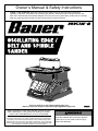
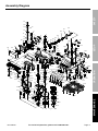
Bauer Item 56870 is a functional benchtop sander designed for home and professional use. This versatile tool excels at sanding, grinding, and smoothing various materials, including wood, metal, and plastic. With its powerful motor and durable construction, it can handle demanding tasks with ease. The sander features a spacious worktable and adjustable miter gauge, providing precise control and support for accurate sanding. Additionally, the dust port allows for easy connection to a dust collection system, maintaining a clean work environment.
Bauer Item 56870 is a functional benchtop sander designed for home and professional use. This versatile tool excels at sanding, grinding, and smoothing various materials, including wood, metal, and plastic. With its powerful motor and durable construction, it can handle demanding tasks with ease. The sander features a spacious worktable and adjustable miter gauge, providing precise control and support for accurate sanding. Additionally, the dust port allows for easy connection to a dust collection system, maintaining a clean work environment.


-
 1
1
-
 2
2
-
 3
3
-
 4
4
-
 5
5
-
 6
6
-
 7
7
-
 8
8
-
 9
9
-
 10
10
-
 11
11
-
 12
12


Bauer 56870 Owner's manual
- Category
- Power tools
- Type
- Owner's manual
- This manual is also suitable for
Bauer Item 56870 is a functional benchtop sander designed for home and professional use. This versatile tool excels at sanding, grinding, and smoothing various materials, including wood, metal, and plastic. With its powerful motor and durable construction, it can handle demanding tasks with ease. The sander features a spacious worktable and adjustable miter gauge, providing precise control and support for accurate sanding. Additionally, the dust port allows for easy connection to a dust collection system, maintaining a clean work environment.
Ask a question and I''ll find the answer in the document
Finding information in a document is now easier with AI
Related papers
-
Bauer 57587 Owner's manual
-
-
Bauer 63999 Owner's manual
-
-
Bauer 58862 Owner's manual
-
Bauer 58862 21107E-B 12 Inch DISC Sander Owner's manual
-
-
-
Other documents
-
Triton TSPST450 User guide
-
Chicago Electric 2 Amp 5 in. Random Orbital Heavy Duty Palm Sander User manual
-
-
PowerTec BD1030 Owner's manual
-
-
Craftsman 113226421 Owner's manual
-
Wen RAT6535 User manual
-
-
Porter-Cable PCB420SA User manual
-
Harbor Freight Tools 6 in. x 9 in. Combination Belt and Disc Sander Owner's manual