Randell Ranserve Mobile System Serving User manual
- Type
- User manual

OPERATOR MANUAL
IMPORTANT INFORMATION, KEEP FOR OPERATOR
Information contained in this document is known to be current and accurate at the time of printing/creation. Unified Brands recommends
referencing our product line websites, unifiedbrands.net, for the most updated product information and specifications. © 2019 Unified Brands.
All Rights Reserved. Unified Brands is a wholly-owned subsidiary of Dover Corporation.
1055 Mendell Davis Drive, Jackson, MS 39272
888-994-7636, fax 888-864-7636
unifiedbrands.net
PART NUMBER PP MNL1902, REV. B (04/20)
This manual provides information for:
RANSERVE MOBILE SERVING
THIS MANUAL MUST BE RETAINED FOR FUTURE REFERENCE. READ,
UNDERSTAND AND FOLLOW THE INSTRUCTIONS AND WARNINGS
CONTAINED IN THIS MANUAL.
FOR YOUR SAFETY Do not store or use gasoline or other flammable vapors
and liquids in the vicinity of this or any other appliance.
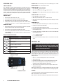
WARNING R290 flammable refrigerant in use. Improper installation,
adjustment, alteration, service or maintenance can cause property
damage, injury or death. Read the installation, operating and maintenance
instructions thoroughly before installing or servicing this equipment.
NOTIFY CARRIER OF DAMAGE AT ONCE It is the responsibility of the
consignee to inspect the container upon receipt of same and to determine
the possibility of any damage, including concealed damage. Unified
Brands suggests that if you are suspicious of damage to make a notation
on the delivery receipt. It will be the responsibility of the consignee to file
a claim with the carrier. We recommend that you do so at once.
Manufacture Service/Questions 888-994-7636.
RETAIN THIS MANUAL FOR FUTURE REFERENCE
NOTICE: Due to a continuous program of product improvement, Unified Brands
reserves the right to make changes in design and specifications without prior notice.
NOTICE: Please read the entire manual carefully before installation. If certain
recommended procedures are not followed, warranty claims will be denied.
MODEL NUMBER _________________________
SERIAL NUMBER _________________________
INSTALLATION DATE ______________________
The serial number tag on Randell refrigerated
equipment is located in the mechanical housing. The
serial number tag on Randell hot food and silverware
stand are located on the far left front side of the unit.
The serial number tag on Randell cashier stands and
cold pans are located on the far left side.
EQUIPMENT DESCRIPTION
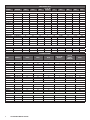
RECESSED COLD PANS
OLD MODEL NEW MODEL LENGTH DEPTH HEIGHT
12 X 20” PAN
CAPACITY
HP VOLTS AMPS NEMA SHIP WT
Closed Base - Steel
RAN SCA-2 RS SSC-RCP-2 36" 30" 35" 2 1/4 115/60/1 3.5 5-15P 250
RAN SCA-3 RS SSC-RCP-3 48" 30" 35" 3 1/4 115/60/1 3.5 5-15P 300
RAN SCA-4 RS SSC-RCP-4 60" 30" 35" 4 1/4 115/60/1 3.5 5-15P 350
RAN SCA-5 RS SSC-RCP-5 72" 30" 35" 5 1/4 115/60/1 3.5 5-15P 400
RAN SCA-6 RS SSC-RCP-6 84" 30" 35" 6 1/4 115/60/1 3.5 5-15P 450
Open Base - Steel
RAN SCA-2S RS SSO-RCP-2 36" 30" 35" 2 1/4 115/60/1 3.5 5-15P 250
RAN SCA-3S RS SSO-RCP-3 48" 30" 35" 3 1/4 115/60/1 3.5 5-15P 300
RAN SCA-4S RS SSO-RCP-4 60" 30" 35" 4 1/4 115/60/1 3.5 5-15P 350
RAN SCA-5S RS SSO-RCP-5 72" 30" 35" 5 1/4 115/60/1 3.5 5-15P 400
RAN SCA-6S RS SSO-RCP-6 84" 30" 35" 6 1/4 115/60/1 3.5 5-15P 450
Closed Base - Fiberglass
RANFG SCA-2 RS FGC-RCP-2 36" 30" 35" 2 1/4 115/60/1 3.5 5-15P 250
RANFG SCA-3 RS FGC-RCP-3 48" 30" 35" 3 1/4 115/60/1 3.5 5-15P 300
RANFG SCA-4 RS FGC-RCP-4 60" 30" 35" 4 1/4 115/60/1 3.5 5-15P 350
RANFG SCA-5 RS FGC-RCP-5 72" 30" 35" 5 1/4 115/60/1 3.5 5-15P 400
RANFG SCA-6 RS FGC-RCP-6 84" 30" 35" 6 1/4 115/60/1 3.5 5-15P 450
Open Base - Fiberglass
RANFG SCA-4S RS FGO-RCP-4 60" 30" 35" 4 1/4 115/60/1 3.5 5-15P 350
RANFG SCA-5S RS FGO-RCP-5 72" 30" 35" 5 1/4 115/60/1 3.5 5-15P 400
RANFG SCA-6S RS FGO-RCP-6 84" 30" 35" 6 1/4 115/60/1 3.5 5-15P 450

2 OM-RANSERVE MOBILE SERVING
RECESSED FROST TOPS
OLD MODEL NEW MODEL LENGTH DEPTH HEIGHT
12 X 20” PAN
CAPACITY
HP VOLTS AMPS NEMA SHIP WT
Closed Base - Steel
RAN FTA-2 RS SSC-RFT-2 36" 30" 35" 2 1/4 115/60/1 3.5 5-15P 190
RAN FTA-3 RS SSC-RFT-3 48" 30" 35" 3 1/4 115/60/1 3.5 5-15P 225
RAN FTA-4 RS SSC-RFT-4 60" 30" 35" 4 1/4 115/60/1 3.5 5-15P 265
RAN FTA-5 RS SSC-RFT-5 72" 30" 35" 5 1/4 115/60/1 3.5 5-15P 310
RAN FTA-6 RS SSC-RFT-6 84" 30" 35" 6 1/4 115/60/1 3.5 5-15P 355
Open Base - Steel
RAN FTA-2S RS SSO-RFT-2 36" 30" 35" 2 1/4 115/60/1 3.5 5-15P 190
RAN FTA-3S RS SSO-RFT-3 48" 30" 35" 3 1/4 115/60/1 3.5 5-15P 225
RAN FTA-4S RS SSO-RFT-4 60" 30" 35" 4 1/4 115/60/1 3.5 5-15P 265
RAN FTA-5S RS SSO-RFT-5 72" 30" 35" 5 1/4 115/60/1 3.5 5-15P 310
RAN FTA-6S RS SSO-RFT-6 84" 30" 35" 6 1/4 115/60/1 3.5 5-15P 355
Closed Base - Fiberglass
RANFG FTA-2 RS FGC-RFT-2 36" 30" 35" 2 1/4 115/60/1 3.5 5-15P 190
RANFG FTA-3 RS FGC-RFT-3 48" 30" 35" 3 1/4 115/60/1 3.5 5-15P 225
RANFG FTA-4 RS FGC-RFT-4 60" 30" 35" 4 1/4 115/60/1 3.5 5-15P 265
RANFG FTA-5 RS FGC-RFT-5 72" 30" 35" 5 1/4 115/60/1 3.5 5-15P 310
RANFG FTA-6 RS FGC-RFT-6 84" 30" 35" 6 1/4 115/60/1 3.5 5-15P 355
Open Base - Fiberglass
RANFG FTA-4S RS FGO-RFT-4 60" 30" 35" 4 1/4 115/60/1 3.5 5-15P 265
RANFG FTA-5S RS FGO-RFT-5 72" 30" 35" 5 1/4 115/60/1 3.5 5-15P 310
RANFG FTA-6S RS FGO-RFT-6 84" 30" 35" 6 1/4 115/60/1 3.5 5-15P 355
ICE COOLED COLD PANS
MODEL NEW MODEL LENGTH DEPTH HEIGHT
12 X 20” PAN
CAPACITY
COLD PAN
INTERIOR
DIMENSIONS
SHIP WT
Closed Base - Steel
RAN IC-2 RS SSC-ICP-2 36" 30" 35" 2 25" x 20" x 6" 140
RAN IC-3 RS SSC-ICP-3 48" 30" 35" 3 38" x 20" x 6" 175
RAN IC-4 RS SSC-ICP-4 60" 30" 35" 4 52" x 20" x 6" 215
RAN IC-5 RS SSC-ICP-5 78" 30" 35" 5 67" x 20" x 6" 260
RAN IC-6 RS SSC-ICP-6 86" 30" 35" 6 76.5" x 20" x 6" 310
Open Base - Steel
RAN IC-2S RS SSO-ICP-2 36" 30" 35" 2 25" x 20" x 6" 140
RAN IC-3S RS SSO-ICP-3 48" 30" 35" 3 38" x 20" x 6" 175
RAN IC-4S RS SSO-ICP-4 60" 30" 35" 4 52" x 20" x 6" 215
RAN IC-5S RS SSO-ICP-5 78" 30" 35" 5 67" x 20" x 6" 260
RAN IC-6S RS SSO-ICP-6 86" 30" 35" 6 76.5" x 20" x 6" 310
Closed Base - Fiberglass
RANFG IC-2 RS FGC-ICP-2 36" 30" 35" 2 - 250
RANFG IC-3 RS FGC-ICP-3 48" 30" 35" 3 - 300
RANFG IC-4 RS FGC-ICP-4 60.25" 30" 35" 4 - 350
RANFG IC-5 RS FGC-ICP-5 78" 30" 35" 5 - 400
RANFG IC-6 RS FGC-ICP-6 86" 30" 35" 6 - 450
Open Base - Fiberglass
RANFG IC-3S RS FCO-ICP-3 48" 30" 35" 3 - 275
RANFG IC-4S RS FCO-ICP-4 60.25" 30" 35" 4 - 325
RANFG IC-5S RS FCO-ICP-5 78" 30" 35" 5 - 375
RANFG IC-6S RS FCO-ICP-6 86" 30" 35" 6 - 425

3 OM-RANSERVE MOBILE SERVING
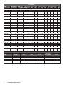
HOT FOOD WELLS
MODEL LENGTH DEPTH HEIGHT
NO. OF
WELLS
NO. OF
ELEMENTS
120V 208V
240V
SHIP
WT.
KW AMPS* NEMA KW AMPS*
NEMA KW AMPS* NEMA
Closed Base - Steel
RAN HTD-2 30" 27" 35" 2 2 2.2 18.4 5-30P 2.2 10.6 6-15P 2.2 9.2 6-15P 175
RAN HTD-3 48" 27" 35" 3 3 3.3 27.6 5-50P 3.3 15.9 6-20P 3.3 13.8 6-20P 215
RAN HTD-4 60" 27" 35" 4 4 4.4 36.8 5-50P 4.4 21.2 6-30P 4.4 18.4 6-30P 260
RAN HTD-5 72" 27" 35" 5 5 5.5 46 - 5.5 27.4 6-50P 5.5 23 6-30P 325
RAN HTD-6 86" 27" 35" 6 6 - - - 6.6 31.7 6-50P 6.6 27.5 6-50P 390
Open Base - Steel
RAN HTD-2S 30" 27" 35" 2 2 2.2 18.4 5-30P 2.2 10.6 6-15P 2.2 9.2 6-15P 175
RAN HTD-3S 48" 27" 35" 3 3 3.3 27.6 5-50P 3.3 15.9 6-20P 3.3 13.8 6-20P 215
RAN HTD-4S 60" 27" 35" 4 4 4.4 36.8 5-50P 4.4 21.2 6-30P 4.4 18.4 6-30P 260
RAN HTD-5S 72" 27" 35" 5 5 5.5 46 - 5.5 27.4 6-50P 5.5 23 6-30P 325
RAN HTD-6S 86" 27" 35" 6 6 - - - 6.6 31.7 6-50P 6.6 27.5 6-50P 390
Heated Base - Steel
RAN HTD-2B 30" 27" 35" 2 2 3.3 27.6 5-50P 3.03 14.6 6-20P 3.3 13.8 6-20P 175
RAN HTD-3B 48" 27" 35" 3 3 4.4 36.8 5-50P 4.125 19.8 6-30P 4.4 18.4 6-30P 215
RAN HTD-4B 60" 27" 35" 4 4 5.5 46 - 5.225 25.1 6-50P 5.5 23 6-30P 260
RAN HTD-5B 72" 27" 35" 5 5 - - - 6.325 30.4 6-50P 6.6 27.5 6-50P 325
RAN HTD-6B 86" 27" 35" 6 6 - - - 7.425 37 6-50P 7.7 32 6-50P 390
Closed Base - Fiberglass
RANFG HTD-2 30" 30" 35" 2 2 2.2 18.4 5-30P 2.2 10.6 6-15P 2.2 9.2 6-15P 175
RANFG HTD-3 48" 30" 35" 3 3 3.3 27.6 5-50P 3.3 15.9 6-20P 3.3 13.8 6-20P 225
RANFG HTD-4 60.25" 30" 35" 4 4 4.4 36.8 5-50P 4.4 21.2 6-30P 4.4 18.4 6-30P 275
RANFG HTD-5 72" 30" 35" 5 5 - - - 5.5 27.4 6-50P 5.5 23 6-30P 325
RANFG HTD-6 86" 30" 35" 6 6 - - - 6.6 31.7 6-50P 6.6 27.5 6-50P 375
Open Base - Fiberglass
RANFG HTD-3S 48" 30" 35" 3 3 3.3 27.6 5-50P 3.3 15.9 6-20P 3.3 13.8 6-20P 225
RANFG HTD-4S 60.25" 30" 35" 4 4 4.4 36.8 5-50P 4.4 21.2 6-30P 4.4 18.4 6-30P 275
RANFG HTD-5S 72" 30" 35" 5 5 - - - 5.5 27.4 6-50P 5.5 23 6-30P 325
RANFG HTD-6S 86" 30" 35" 6 6 - - - 6.6 31.7 6-50P 6.6 27.5 6-50P 375
Heated Base - Fiberglass
RANFG HTD-4B 60.25" 30" 35" 4 4 - - - 5.225 25.1 6-50P 5.5 23 6-30P 400
RANFG HTD-6B 86" 30" 35" 6 6 - - - 7.425 36 6-50P 7.7 32 6-50P 500
SERVING
MODEL NEW MODEL LENGTH DEPTH HEIGHT
NO OF 5 1/4" DIA
VERTICAL SILVERWARE
BINS
SHIP WT
RAN SW-8 RS SSC-TSW-8 30" 30" 35" 8 110
RAN SW-12 RS SSC-TSW-12 36" 30" 35" 12 120
RAN CA RS SSO-CS 30" 30" 35" - 135
RAN FGSW-8 RS FGC-TSW-8 30" 30" 35" 8 135
RAN FGSW-12 RS FGC-TSW-12 36" 30" 35" 12 135
RANFG CA RS FGO-CS 30" 30" 35" - 135

4 OM-RANSERVE MOBILE SERVING
INSTALLATION
CAUTION:
THIS UNIT CONTAINS R290 FLAMMABLE REFRIGERANT. SEE ABOVE CAUTION.
CAUTION:
UNIT MUST BE INSTALLED INTO IT’S OWN COMPARTMENT TO PROPERLY
CONTAIN ANY REFRIGERANT LEAK. IT IS REQUIRED THAT NO ARCHING
POTENTIAL COMPONENTS (GFCI) OR ELECTRICAL CONNECTIONS ARE
BELOW 14.5” FROM THE BOTTOM OF THE CABINET.
WARNING:
FAILURE TO FOLLOW INSTALLATION GUIDELINES AND RECOMMENDATIONS
MAY VOID THE WARRANTY ON YOUR UNIT.
WARNING: IT IS IMPORTANT THAT YOUR UNIT HAS ITS OWN DEDICATED LINE.
CONDENSING UNITS ARE DESIGNED TO OPERATE WITH A VOLTAGE
FLUCTUATION OF PLUS OR MINUS 10% OF THE VOLTAGE INDICATED ON
THE UNIT DATA TAG. BURN OUT OF A CONDENSING UNIT DUE TO EXCEEDING
VOLTAGE LIMITS WILL VOID THE WARRANTY.
THE DANFOSS CONTROLLER HAS LOW VOLTAGE PROTECTION AND WILL NOT
OUTPUT VOLTAGE TO THE COMPRESSOR IF VOLTAGE IS LESS THAN 104V.
WARNING: IT IS IMPORTANT THAT A VOLTAGE READING BE MADE AT THE COMPRESSOR
MOTOR ELECTRICAL CONNECTIONS, WHILE THE UNIT IS IN OPERATION
TO VERIFY THE CORRECT VOLTAGE REQUIRED BY THE COMPRESSOR IS
BEING SUPPLIED. LOW OR HIGH VOLTAGE CAN DETRIMENTALLY AFFECT
OPERATION AND THEREBY VOID ITS WARRANTY.
WARNING: THIS UNIT IS INTENDED FOR USE IN LABORATORIES IN COMMERCIAL,
INDUSTRIAL, OR INSTITUTIONAL OCCUPANCIES AS DEFINED IN THE
SAFETY STANDARD FOR REFRIGERATION SYSTEMS, ASHRAE 15.
SELECTING A LOCATION FOR YOUR NEW UNIT
The following conditions should be considered when selecting a location for your unit:
1. Floor: The area on which the unit will rest must be level, free of vibration,
and suitably strong enough to support the combined weights of the unit plus
the maximum product load weight.
2. Clearance: Do not place any object that can block the ventilation exhaust
from the machine compartment register. 20 inch clearance at the louvered
end of the unit. Area of equipment must be free of all combustible materials.
3. Ventilation:
Avoid surrounding your unit around other heat generating
equipment and out of direct sunlight. Avoid locating in an unheated room or
where the room temperature may drop below 70° F (21°C) or above 86°F
(32°C).
ELECTRICAL SUPPLY
The wiring should be done by a qualified electrician in accordance with local electrical
codes. A properly wired and grounded outlet will assure proper operation. Please
consult the data tag attached to the compressor to ascertain the correct electrical
requirements. Supply voltage and amperage requirements are located on the serial
number tag.
INSTALLATION CHECKLIST
After the final location of the unit has been determined refer to the following checklist
prior to start up:
1. Check all exposed refrigeration lines to ensure that they are not kinked, dented or
rubbing together.
2. Check all visible components for any potential damage.
3. Check that condenser fans rotate freely without striking any stationary members.
4. Unit must be properly leveled.
5. Unit must be property leveled; Check all legs or casters ensure they all are in
contact with the floor while maintaining a level work surface. Adjusting bullet
feet height or shimming casters may be necessary if the floor is not level. NOTE:
Damage to equipment may result if not followed. Unified Brands is not responsible
for damage to equipment in improperly installed.
6. Plug unit into power source. Unit will come on. If unit does not turn on, refer to
controller operation section of this manual to manually turn on the unit.
7. Allow unit 50-60 minutes to cool down to temperature. If temperature adjustments
are required, refer to controller operation section of this manual to adjust the
temperature. Confirm that the unit is holding the desired temperature.
8. Refer to the front of this manual for serial number location. Please record this
information in your manual now. It will be necessary when ordering replacement
parts or requesting warranty service.
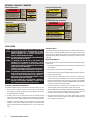
IMPORTANT - READ FIRST - IMPORTANT
INTERIOR EVAPORATOR COVER
EXTERIOR OF UNIT
RISK OF FIRE OR EXPLOSION.
FLAMMABLE REFRIGERANT USED.
DO NOT USE MECHANICAL DEVICES
TO DEFROST REFRIGERATOR. DO NOT
PUNCTURE REFRIGERANT TUBING.
RIESGO DE INCENDIO O EXPLOSIÓN. REFRIGERANTE INFLAMABLE UTILIZADO. NO
UTILICE DISPOSITIVOS MECÁNICOS PARA DESCONGELAR EL REFRIGERADOR. NO
PERFORE LA TUBERÍA DEL REFRIGERANTE.
RISQUE D’INCENDIE OU
D’EXPLOSION.
INFLAMMABLE
RÉFRIGÉRANT UTILISÉ.
NE PAS UTILISER DE
DISPOSITIFS
MÉCANIQUES POUR
DÉGIVRER LE
RÉFRIGÉRATEUR. NE
FAIRE AUCUN TUBE
RÉFRIGÉRANT DE
PONCTION.
DANGER
SB6.1.2
WARNING ALERTE
CAUTION ATTENTIÓN
DO NOT REMOVE PANEL - HIGH VOLTAGE -
QUALIFIED PERSONNEL ONLY
NE PAS RETIRE LE PANNEAU - HAUTE TENSION -
PERSONNEL QUALIFIÉ SEULEMENT
NO RETIRE EL PANEL - ALTA TENSIÓN -
CALIFICADO PERSONAL
MOVING PARTS, DO NOT OPERATE
WITH COVER REMOVED
PIÉCES MOBILES NE PAS FAIRE
FONCTIONNER SANS COUVERCLE
LAS PIEZAS DE MOVIMIENTO NO FUNCIONAN
CON LA CUBIERTA RETIRADA
PP LBL1701 REV B
LABEL DIMENSION: 9 in x 3.25 in
RISK OF FIRE OR EXPLOSION.
DISPOSE OF PROPERLY IN
ACCORDANCE WITH FEDERAL OR
LOCAL REGULATIONS.
FLAMMABLE REFRIGERANT USED.
PRECAUCIÓN RIESGO DE INCENDIO O EXPLOSIÓN. DESÉCHELO ADECUADAMENTE CONFORME
A REGLAMENTOS FEDERALES O LOCALES. REFRIGERANTE INFLAMABLE UTILIZADO.
MISE EN GARDE RISQUE
D’INCENDIE OU
D’EXPLOSION. ÉLIMINER
(or DISPOSER)
CORRECTEMENT
CONFORMÉMENT AUX
RÉGLEMENTATIONS
FÉDÉRALES OU LOCALES.
RÉFRIGÉRANT
INFLAMMABLE UTILISÉ.
SB6.1.4
LABEL DIMENSION: 6 in x 2.75 in
PP LBL1704 REV B
CAUTION
RISK OF FIRE OR EXPLOSION DUE TO
PUNCTURE OF REFRIGERANT TUBING; FOLLOW
HANDLING INSTRUCTIONS CAREFULLY.
FLAMMABLE REFRIGERANT USED.
PRECAUCIÓN RIESGO DE INCENDIO O EXPLOSIÓN DEBIDO A LA PERFORACIÓN DE LA TUBERÍA DE
REFRIGERANTE; SIGA CUIDADOSAMENTE LAS INSTRUCCIONES DE MANEJO. REFRIGERANTE
INFLAMABLE UTILIZADO.
MISE EN GARDE RISQUE
D’INCENDIE OU
D’EXPLOSION EN RAISON
DE LA PERFORATION DU
TUBE RÉFRIGÉRANT;
SUIVEZ ATTENTIVEMENT
LES INSTRUCTIONS DE
MANIPULATION.
RÉFRIGÉRANT
INFLAMMABLE UTILISÉ.
CAUTION
SB6.1.5
PP LBL1705 REV B
LABEL DIMENSION: 6.25 in x 2.8 in
RISK OF FIRE OR EXPLOSION. FLAMMABLE
REFRIGERANT USED. CONSULT REPAIR MANUAL
/ OWNER’S GUIDE BEFORE ATTEMPTING TO
INSTALL OR SERVICE THIS PRODUCT. ALL
SAFETY PRECAUTIONS MUST BE FOLLOWED.
PRECAUCIÓN RIESGO DE INCENDIO O EXPLOSIÓN. REFRIGERANTE INFLAMABLE UTILIZADO. CONSULTE EL MANUAL DE REPARACIÓN /
MANUAL DEL USUARIO ANTES DE INSTALAR O REPARAR ESTE PRODUCTO. DEBEN SEGUIRSE LAS PRECAUCIONES DE SEGURIDAD.
MISE EN GARDE RISQUE
D’INCENDIE OU
D’EXPLOSION. RÉFRIGÉRANT
INFLAMMABLE UTILISÉ.
CONSULTER LE MANUEL DE
RÉPARATION / GUIDE DE
L’UTILISATEUR AVANT
D’ESSAYER D’INSTALLER OU
DE RÉPARER CE PRODUIT.
TOUTES LES PRÉCAUTIONS
DOIVENT ÊTRE RESPECTÉES.
SB6.1.3.b
PP LBL1703 REVB
LABEL DIMENSION: 7.5 in x 5.36 in
SB6.1.3.a
RISK OF FIRE OR EXPLOSION. FLAMMABLE
REFRIGERANT USED. TO BE REPAIRED ONLY
BY TRAINED SERVICE PERSONNEL. DO NOT
PUNCTURE REFRIGERANT TUBING.
PELIGRO RIESGO DE INCENDIO O EXPLOSIÓN. REFRIGERANTE INFLAMABLE UTILIZADO. DEBE SER REPARADO
SOLAMENTE POR PERSONAL DE SERVICIO CAPACITADO. NO PERFORE LA TUBERÍA DEL REFRIGERANTE.
DANGER RISQUE
D’INCENDIE OU
D’EXPLOSION.
RÉFRIGÉRANT
INFLAMMABLE UTILISÉ.
POUR ÊTRE RÉPARÉ QUE
PAR UN TECHNICIEN
QUALIFIÉ. NE PAS
PERFORER LE TUBE
RÉFRIGÉRANT.
CAUTION
DANGER
NEAR EXPOSED REFRIGERANT TUBING
NEAR MACHINE COMPARTMENT AND NAMEPLATE

5 OM-RANSERVE MOBILE SERVING
POWER ON / OFF: Press and hold the power button until LED display turns On / Off
MANUAL DEFROST: Press and hold “Defrost” Button
CHANGE SET POINT: To raise temperature
1. Press and hold “ ” to access set point.
2. When set point start flashing, Press “ ” to adjust set point.
3. After 30 seconds, the display automatically reverts to showing the current
temperature.
CHANGE SET POINT: To lower temperature
1. Press and hold “v” to access set point.
2. When set point start flashing, Press “v” to adjust set point.
3. After 30 seconds, the display automatically reverts to showing the current
temperature.
CHANGE FROM ºF /ºC :
1. Press the up/down buttons simultaneously for 5 seconds to access the menu.
2. Password is requested. Password is 000.
3. Press the bottom left button to OK the password.
4. Using the up/down buttons, navigate to the “diS” level. Press the bottom left
button to OK the selection.
5. Using the up/down buttons, navigate to the “CFu” level. Press the bottom left
button to OK the selection.
a. “-F” designates Fahrenheit.
b. “-C” designates Celsius.
6. Press the top left button repeatedly to return to exit and return to the home
screen.
OPERATION - HOT
CAUTION: MOISTURE COLLECTING FROM IMPROPER DRAINAGE CAN CREATE A
SLIPPERY SURFACE ON THE FLOOR AND HAZARD TO EMPLOYEES. WHEN
MAKING ELECTRICAL CONNECTIONS REFER TO THE AMPERAGE DATA
LISTED ON THE UNIT’S DATA PLATE. REFERENCE YOUR LOCAL CODE
OR THE NATIONAL ELECTRICAL CODE HANDBOOK TO ENSURE THE UNITS
CONNECTED TO THE PROPER POWER SOURCE.
Switch the master switch, located on the control panel, to hot and the red indicator
light will illuminate. All units are design for 145 to 175ºF operation or 140 to 170ºF
product temperature. When used as a hot well the unit must have water in it all
all times. Failure to use water or to add water when the unit is heating may cause
damage to the unit.
1. Add 1” to 2” of water to holding tank. Hot water is recommended.
2. Turn thermostat to #4
3. Red indicator light will energize to show corresponding well that is heating.
4. Wait 1 hour before adjusting thermostat. Higher number will increase
temperature. Lower number will decrease temperature.
5. Turn thermostat to off position when operation is completed. Switch master
switch to the off position.
Refilling of wet operation units is required periodically if the water level is lower
than1.” NOTE: Do not add water to an empty hot well that is at holding temperature.
PLUMBING
The units drain must have an outlet to an appropriate drainage area or container.
NOTE: Electric Elements are not submersible.
NOTE: Drains must be plumbed according to all applicable local code requirements.
OPERATION - COLD
AMBIENT CONDITIONS
Unit is designed for normal operating temperatures are between 70°F (21°C)
and 86°F (32°C). Operating outside of those temperatures may cause premature
product wear or failure. Unified Brands has attempted to preset the temperature
control to ensure that your unit runs at an optimum temperature, but due to varying
ambient conditions, including elevation, food type and your type of operation,
you may need to alter this temperature using control adjustment until desired
temperature is reached.
MORNING STARTUP
1. Unit cleaning may be performed at this time.
2. Turn on power to unit by pushing the controller power button.
3. Allow 50-60 minutes for your unit to cool down before loading product.
4. Load the product and proceed with food preparation. NOTE: Product entering
the cold pan must be at 37°F +/- 2°F or less. All pans should be in position.
EVENING SHUT DOWN
1. Remove product from the unit at the end of the day’s preparation. The product
may be discarded or stored in any commercial refrigerator.
2. Turn off power to unit by pushing the controller power button.
3. Unit cleaning may be performed at this time once the frost has melted off the
surface. NOTE: Water may form small pools and have to be pushed to the drain
for 100% draining.
DANFOSS CONTROLLER OPERATION
LED FUNCTION
Compressor energized & Evaporator fan de-energized
Defrost in progress
Fans delay after defrost completion
Evaporator fan energize
An alarm is occurring
ºC / ºF
Temperature unit
POWER ON / OFF
MANUAL DEFROST
CHANGE SET POINT

6 OM-RANSERVE MOBILE SERVING
MAINTENANCE
WARNING: DO NOT USE SHARP UTENSILS AND/OR OBJECTS.
WARNING: DO NOT USE STEEL PADS, WIRE BRUSHES, SCRAPERS, OR CHLORIDE
CLEANERS TO CLEAN YOUR STAINLESS STEEL.
CAUTION: DO NOT USE ABRASIVE CLEANING SOLVENTS, AND NEVER USE
HYDROCHLORIC ACID (MURIATIC ACID) ON STAINLESS STEEL.
WARNING: DO NOT PRESSURE WASH EQUIPMENT AS DAMAGE TO ELECTRICAL
COMPONENTS MAY RESULT.
Unified Brands strongly suggests a preventive maintenance program which would
include the following monthly procedures:
If a failure of the equipment is a direct result of any of the Preventative Maintenance
guidelines being neglected, the repairs and parts replacements will not be covered
under warranty.
It is recommended that the customer contact the local Authorized Service Agent to
provide a quote to perform periodic Preventative Maintenance.
MONTHLY PROCEDURES
1.
Cleaning of all condenser coils. Condenser coils are a critical component in the
life of the compressor and must remain clean to assure proper air flow and heat
transfer. Failure to maintain this heat transfer will affect unit performance and
eventually destroy the compressor. Clean the condenser coils with coil cleaner
and/or a vacuum cleaner and brush. NOTE: Brush coil in direction of fins, normally
vertically as to not damage or restrict air from passing through condenser.
2. Clean fan blades on the condensing unit.
3. Clean and disinfect drain lines with a solution of warm water and mild
detergent.
4. Check silicone seal around drop in flange for peeling and cracks. Reapply with
food grade silicone as necessary.
RECOMMENDED CLEANERS FOR YOUR STAINLESS STEEL INCLUDE THE
FOLLOWING:
JOB CLEANING AGENT COMMENTS
Routine cleaning
Soap, ammonia,
detergent Medallion
Apply with a sponge or
cloth
Fingerprints and smears
Arcal 20, Lac-O-Nu,
Ecoshine
Provides a barrier film
Stubborn stains and
discoloration
Cameo, Talc, Zud,
First Impression
Rub in the direction of
the polish lines
Greasy and fatty acids, blood,
burnt-on foods
Easy-Off, Degrease It,
Oven Aid
Excellent removal on all
finishes
Grease and Oil
Any good commercial
detergent
Apply with a sponge or
cloth
Restoration/Preservation Benefit, Super Sheen Good idea monthly
Reference: Nickel Development Institute, Diversey Lever, Savin, Ecolab, NAFEM
Proper maintenance of equipment is the ultimate necessity in preventing costly
repairs. By evaluating each unit on a regular schedule, you can often catch
and repair minor problems before they completely disable the unit and become
burdensome on your entire operation.
For more information on preventive maintenance, consult your local service
company or CFESA member. Most repair companies offer this service at very
reasonable rates to allow you the time you need to run your business along with
the peace of mind that all your equipment will last throughout its expected life.
These services often offer guarantees as well as the flexibility in scheduling or
maintenance for your convenience. For a complete listing of current Unified Brands
ASA please visit www.unifiedbrands.net.
Unified Brands believes strongly in the products it manufactures and backs those
products with one of the best warranties in the industry. We believe with the
proper maintenance and use, you will realize a profitable return on your investment
and years of satisfied service.
REPLACEMENT PARTS
To order parts, contact your Authorized Service Agent. Supply the model
designation, serial number, part description, part number, quantity, and when
applicable, voltage and phase.
CONTACT US
If you have questions pertaining to the content in this manual, contact Unified
Brands at 888-994-7636 or tsrandell@unifiedbrands.net.
TROUBLESHOOTING
This unit is designed to operate smoothly and efficiently if properly maintained.
However, the following is a list of checks to make in the event of a problem.
Wiring diagrams are found at the end of this manual. When in doubt, turn unit off
and contact service at 888-994-7636 or tsrandell@unifiedbrands.net.
SYMPTOM - COLD POSSIBLE CAUSE PROCEDURE
Unit does not run
No power to unit Plug in unit
Control in OFF position Turn controller on
Faulty control
Call for service at
888-994-7636
Unit too cold Incorrect set point Adjust control set point
Unit too warm Incorrect set point Adjust control set point
Unit noisy Vibration in the cabinet Inspect for loose parts
SYMPTOM - HOT POSSIBLE CAUSE PROCEDURE
Unit doesn’t heat
No power to unit Plug in unit
Temperature control turned
off
Check temperature control
Temperature control faulty Test temperature control
Element does not heat Test element for continuity
Unit too hot Thermostat not shutting off Test thermostat
Unit runs constantly
Too much water in tank 1” - 2” of water in the tank
Thermostat sensing bulb Check location of sensing bulb
Unit leaking water
Drain Check drains for leaks
Pan cracked Call ASA for repair

7 OM-RANSERVE MOBILE SERVING
DANFOSS CONTROLLER CODES
DISPLAYED
ALARM CODE
ALARM ACTION
Hi High Temperature Alarm
Inspect door/drawer sealing
Contact service
Lo Low Temperature Alarm Contact service
CON
Condenser Temperature
High Limit
Clean condenser coil
Inspect coil for any objects
obstruction hindering airflow
Contact service
uHi Line Voltage Too High
Verify voltage of power source,
to be performed by qualified
technician
Contact service
uLi Line Voltage Too Low
Verify voltage of power source,
to be performed by qualified
technician
Contact service
LEA
Continuous Compressor
Runtime
Inspect door/drawer sealing
Inspect condenser coil, clean if
necessary
Contact service
E01 S1 Sensor Failure Contact service
E02 S2 Sensor Failure Contact service
E03 S3 Sensor Failure Contact service
E04 S4 Sensor Failure Contact service
SERVICE - COLD
CAUTION: COMPONENT PARTS SHALL BE REPLACED WITH FACTORY OEM PARTS.
SERVICE WORK SHALL BE DONE BY FACTORY AUTHORIZED SERVICE
PERSONNEL, SO AS TO MINIMIZE THE RISK OF POSSIBLE IGNITION DUE TO
INCORRECT PARTS OR IMPROPER SERVICE.
CAUTION: BEFORE MAKING ANY REPAIRS, ENSURE THE UNIT IS DISCONNECTED
FROM ITS POWER SOURCE.
This piece of equipment uses a R290 Refrigeration system. This equipment has
been clearly marked on the serial tag the type of refrigerant that is being used.
There is also a warning labels stating that the unit contains R290 refrigerant. R290
is safe to use as long as you follow these warning labels.
No smoking or open flames when servicing this equipment. If needed, use a CO2
or dry-powder type fire extinguisher.
Replacement parts used on any R290 Refrigeration system cabinet must have
specific UL certification for non-sparking components.
Only authorized service technician, certified in R290 system should service this
equipment.
MANIFOLD SET
A R134A manifold set can be used for servicing this equipment.
REFRIGERANT RECOVERY
Follow all national and local regulations for R-290 refrigerant recovery.
LEAKING CHECKING AND REPAIR
Leak check an R-290 system the same way you would an R-134a or R-404A
system with the following exceptions.
1. Do not use a Halid leak detector on a R290 system.
2. Electronic leak detector must be designated specifically for combustible gas.
Use of a bubble solution or an ultrasonic leak detector are acceptable.
When repairing a leak, it is recommended using oxygen free dry nitrogen with a
trace gas not exceeding 200PSI.
When accessing an R290 system, piercing valves are not to remain on the
equipment in a permanent manner. After charge is recovered, Schrader valves
are to be installed on the process stubs. Proper charge is to be weighed into the
system and the system is to be leak checked afterwards.
The R290 equipment must have red process tubes and other devices through
which the refrigerant is serviced, such as any service port. This color marking
must remain on the equipment. If marking is removed, it must be replace and
extend at least 2.5 centimeters (1”) from the compressor.
CHARGING
Follow the charge amount specified on the data tag. It is recommended to use the
shortest hoses possible to prevent undercharging.
• Ensure the system is sealed and leak checked
• Evacuate system to a minimum 500 micron
• Weigh in correct charge
• Leak check the system again
• Bleed the refrigerant from the high side hose to the low side hose
• Disconnect the hoses
• Remove line taps

8 OM-RANSERVE MOBILE SERVING
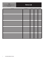
Parts List
COLD
CALL FACTORY FOR REPLACEMENT PARTS:
888-994-7636
DESCRIPTION PART NUMBER Cold Pan Frost Top Ice Cooled
NON-LOCKING CASTER HD CST1702 X X X
LOCKING CASTER HD CST1701 X X X
LOUVER - FIBERGLASS ONLY, HINGED RP LVR1901 X X -
LOUVER - FIBERGLASS ONLY, REMOVABLE RP LVR1902 X X -
POWER CORD, 9' 16/3 W/90* EL WIR1703 X X X
DRAIN, 1" , GREY HD DRN1702 X X -
DRAIN VALVE PB VLV0102 X X -
DRAIN SCREEN RP DSN001 X X -
ADAPTER BARS RP BAR020 X - -
LOCKING MECHANISM, RANSERVE HD LCK0201 X X X
MOUNT, COMPRESSOR BASE SKID RP MNT1901 X X -
ACCUMULATOR RF ACM1701 X X -
FILTER DRYER RF FLT9902 X X -
FAN GUARD RF FAN1602 X X -
FAN GUARD RF FAN0703 - X -
FAN, AXIAL, CONDENSER RF FAN0601 X - -
FAN, AXIAL, CONDENSER RF FAN1401 - X -
SHROUD, FAN RP HSG1803 - X -
CONDENSER COIL RF COI1603 X X -
CAP TUBE WRAP W/ HEAT EXCHANGE RP WRP1802 X X -
COMPRESSOR, 1/4HP, R290, EMBRACO EM2X3125U RF CMP1604 X X -
START COMPONENTS RF CMP1604SC X X -
DANFOSS CONTROL, PROGRAMMED - RCP RP CNT1803 X
-
-
DANFOSS CONTROL, PROGRAMMED, - RFT RP CNT1901 -
X
-
SENSOR, COIL RF CNT1603 X
X
-
BRACKET, FOLDING TRAYSLIDE HD BRK0201 X
X
X
BRACKET, FOLDING 3 RAIL TRAY SLIDE HD BRK210 X
X
X
LIGHT FIXTURE CONSULT FACTORY X
X
X

9 OM-RANSERVE MOBILE SERVING
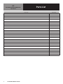
Parts List
HOT
CALL FACTORY FOR REPLACEMENT PARTS:
888-994-7636
DESCRIPTION PART NUMBER
NON-LOCKING CASTER HD CST1702
LOCKING CASTER HD CST1701
LOCKING MECHANISM, RANSERVE HD LCK0201
THERMOSTAT EL HFT1601
CONTROL KNOB HD KNB1701
BEZEL FOR THERMOSTAT HD GRD0203
PILOT LIGHT EL LGT500
CONTROL KNOB GUARD RP GRD230
HEATING ELEMENT, 120V RP ELM1100B
HEATING ELEMENT, 208V, 1100W RP ELM1172B
HEATING ELEMENT, 240V, 1100W RP ELM1124B
BAR HEATING ELEMENT, 240V EL HTR750
ELEMENT PAN / NO ELEMENT RP EPN005
ELEMENT PAN / WITH ELEMENT - 208V RP EPN208
ELEMENT PAN / WITH ELEMENT - 240V RP EPN240
WELL ASSY, 120V ELEMENT, W/ DRAIN RP WEL0001
WELL ASSY, 208V ELEMENT, W/ DRAIN RP WEL0003
WELL ASSY, 240V ELEMENT, W/ DRAIN RP WEL0004
DRAIN SREEN, HFW RP SCN001
BALL VALVE - 1/2" PB VLV501
BALL VALVE - 1/2" W/ EXT HANDLE RP VLV501
EXTENDED HANDLE ONLY - DRAIN VALVE RP HDL1701
PAN WITH DRAIN, 12 X 20 RP PAN0005
POWER CORD CONSULT FACTORY
PLUG for POWER CORD CONSULT FACTORY
BRACKET, FOLDING TRAYSLIDE HD BRK0201
BRACKET, FOLDING 3 RAIL TRAY SLIDE HD BRK210
SWITCH, HI LIMIT, HTD-B MODELS ONLY EL SWT1902

10 OM-RANSERVE MOBILE SERVING
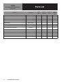
Parts List
SERVING
CALL FACTORY FOR REPLACEMENT PARTS:
888-994-7636
DESCRIPTION PART NUMBER
CASHIER
STAND
COUNTER
PROTECTOR
S/S WORK TOP
UNIT
TRAY &
SILVERWARE
STAND
NON-LOCKING CASTER HD CST1702 X - X X
LOCKING CASTER HD CST1701 X - X X
PANEL, STAINLESS - SPECIFY DIMENSIONS RP PNL1604 X - X X
PERFORATED SILVERWARE INSERT HD INS100 - - - X
LOCKING MECHANISM, RANSERVE HD LCK0201 X - X X
DRAWER ASSEMBLY CONSULT FACTORY X - - -
DRAWER TRACKE, S35-1020 HD TRK004 X - - -
HANDLE, DRAWER 4" HD HDL010 X - - -
PAMINATE PANEL, SPECIFICY DIMENSIONS,
MFG OF LAMINATE, COLOR & COLOR CODE
RP PNL1605 X - X X
GLASS W/ FRAME, SPECIFY DIMENSIONS CONSULT FACTORY - - - -
GLASS, TEMPERED, SPECIFY DIMENSIONS CONSULT FACTORY - X - -
BRACKET ADJ. SNEEZEGUARD HD BRK215 - X - -
BRACKET, FIXED GLASS CONSULT FACTORY - X - -
BRACKET, FOLDING TRAYSLIDE HD BRK0201 X - X X
BRACKET, FOLDING 3 RAIL TRAY SLIDE HD BRK210 X - X X

11 OM-RANSERVE MOBILE SERVING
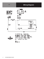
Wiring Diagram
COLD

12 OM-RANSERVE MOBILE SERVING
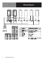
Wiring Diagram
HOT

13 OM-RANSERVE MOBILE SERVING
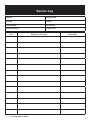
Service Log
Model No: Purchased From:
Serial No: Location:
Date Purchased: Date Installed:
Purchase Order No: For Service Call:
Date Maintenance Performed Performed By
-
 1
1
-
 2
2
-
 3
3
-
 4
4
-
 5
5
-
 6
6
-
 7
7
-
 8
8
-
 9
9
-
 10
10
-
 11
11
-
 12
12
-
 13
13


Randell Ranserve Mobile System Serving User manual
- Type
- User manual
Ask a question and I''ll find the answer in the document
Finding information in a document is now easier with AI
Related papers
-
Randell 2000 Series Reach-Ins Addendum Owner's manual
-
-
Randell 9560 Drop In Series Heated Wells User manual
-
-
-
Randell 3415 Owner's manual
-
-
Randell CR9046 Operating instructions
-
-
Other documents
-
Avantco 360CPT40 User manual
-
Avantco 360GSM3 Series User manual
-
Avantco 178SSCFT72HC User manual
-
Avantco 189 Series Vertical Open Air Merchandisers User manual
-
Avantco 178DLC36HCB User manual
-
Avantco 178GDC15HC User manual
-
Avantco 360BCSS35HCW User manual
-
-
-
Chief Manufacturing SSC-3 User manual