Page is loading ...

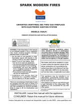
Installation and Operation Instructions
Unvented (Vent-Free) Compact Fireplaces
P/N 126871-01 REV. B 04/2018
VCM3026ZTN
VCM3026ZTP
Models
INSTALLER: Leave this manual with the appliance.
CONSUMER: Retain this manual for future reference.
This appliance may be installed in an aftermarket permanently located, manufactured (mobile) home,
where not prohibited by local codes. This appliance is only for use with the type of gas indicated on the
rating plate. This appliance is not convertible for use with other gases.
This is an unvented gas-fi red heater. It uses air (oxygen) from the room in which it is installed. Provisions
for adequate combustion and ventilation air must be provided. Refer to Air for Combustion and Ventilation
section on Page 7 of this manual.
PFS
®
US
Report No. F09-123
WARNING:
FIRE OR EXPLOSION HAZARD
Failure to follow safety warnings exactly could result in serious injury, death, or property damage.
- Do not store or use gasoline or other fl ammable vapors and liquids in the vicinity of this or any other
appliance.
- WHAT TO DO IF YOU SMELL GAS
• Do not try to light any appliance.
• Do not touch any electrical switch; do not use any phone in your building.
• Leave the building immediately.
• Immediately call your gas supplier from a neighbor’s phone. Follow the gas supplier’s instructions.
• If you cannot reach your gas supplier, call the fi re department.
- Installation and service must be performed by a qualifi ed installer, service agency or the gas supplier.
P126871-01

SuperiorFireplaces.us.com
126871-01B2
TABLE OF CONTENTS
Safety .................................................................. 2
Product Identifi cation ........................................... 4
Local Codes......................................................... 5
Product Features ................................................. 5
Unpacking............................................................ 6
Assembly ............................................................. 6
Air for Combustion and Ventilation ...................... 7
Installation ......................................................... 10
Operation ........................................................... 20
Inspecting Burner .............................................. 23
Cleaning and Maintenance ................................ 24
Troubleshooting ................................................. 25
Specifi cations .................................................... 29
Service Hints ..................................................... 29
Technical Service............................................... 29
Replacement Parts ............................................ 29
Accessories ....................................................... 30
Parts .................................................................. 31
Warranty ............................................................ 35
SAFETY
Early signs
of carbon monoxide poisoning resemble the
fl u, with headaches, dizziness, or nausea. If
you have these signs, the heater may not be
working properly. Have
heater serviced. Some people are more af-
fected by carbon monoxide than others. These
include pregnant women, people with heart or
lung disease or anemia, those under the infl u-
ence of alcohol, and those at high altitudes.
Natural and
propane/LP gases are odorless. An odor-
making agent is added to the gas. The odor
helps you detect a gas leak. However, the
odor added to the gas can fade. Gas may be
present even though no odor exists.
Make certain you read and understand all
warnings. Keep this manual for reference.
It is your guide to safe and proper operation
of this heater.
Air for Combustion and
Ventilation Page 7

SuperiorFireplaces.us.com
126871-01B 3
SAFETY
Continued

SuperiorFireplaces.us.com
126871-01B4
SAFETY
Continued
2. Do not place propane/LP supply tank(s)
inside any structure. Locate propane/
LP supply tank(s) outdoors (propane/LP
only).
3. If you smell gas
• shut off gas supply
• do not try to light any appliance
• do not touch any electrical switch; do not
use any phone in your building
• immediately call your gas supplier from
a neighbor’s phone. Follow the gas sup-
plier’s instructions
• if you cannot reach your gas supplier,
call the fi re department
4. This fi replace shall not be installed in a
bedroom or bathroom.
5. Do not use this fi replace as a wood-burn-
ing fi replace. Use only the logs provided
with the fi replace.
6. Do not add extra logs or ornaments such
as pine cones, vermiculite, or glowing em-
bers (rockwool). Using these added items
can cause sooting. Do not add volcanic
stone around base. Volcanic Stone and
debris could fall into the control area of
fi replace.
7. This fi replace is designed to be smoke-
less. If logs ever appear to smoke, turn
off fi replace and call a qualifi ed service
person.
NOTE
8. To prevent the creation of soot, follow the
instructions in ,
Page 25.
9. Before using furniture polish, wax, carpet
cleaner, or similar products, turn heater
off. If heated, the vapors from these prod-
ucts may create a white powder residue
within burner box or on adjacent walls or
furniture.
10. This fi replace needs fresh air ventilation to
run properly. This fi replace has an Oxygen
Depletion Sensing (ODS) safety shutoff
system. The ODS shuts down the fi re-
place if not enough fresh air is available.
See ,
Page 7. If fi replace keeps shutting off, see
, Page 26.
11. Do not run fi replace
• where fl ammable liquids or vapors are
used or stored.
• under dusty conditions.
12. Do not use this fi replace to cook food or
burn paper or other objects.
13. Never place any objects in the fi replace
or on logs.
14. Do not use fi replace if any part has been
under water. Immediately call a qualifi ed
service technician to inspect the room
fi replace and to replace any part of the
control system and any gas control which
has been under water.
15. Turn off and unplug fireplace and let
cool before servicing. Only a qualifi ed
service person should service and repair
fi replace.
16. Operating fi replace above elevations of
4,500 feet could cause pilot outage.
17. Do not operate fireplace if any log is
broken. Do not operate fi replace if a log
is chipped (dime-sized or larger).
18. To prevent performance problems, do not
use propane/LP fuel tank of less than 100
lbs. capacity (propane/LP only).
19. Provide adequate clearances around air
openings.
20. The screen or any other part removed for
servicing must be replaced prior to operat-
ing this heater.

SuperiorFireplaces.us.com
126871-01B 5
Figure 1 - Vent-Free Gas Compact Fireplace
PRODUCT IDENTIFICATION
Igniter Button
Screen
Fireplace Cabinet
Logs
Control Knob
Left Side
Right Side
Front
LOCAL CODES
Install and use fi replace with care. Follow all
local codes. In the absence of local codes,
use the latest edition of
*. Firebox must
be electrically grounded in accordance with
the
(latest edition).
These appliances are approved for installation in the US state of Massachusetts if the fol-
lowing additional requirements are met:
• Un-vented Room Heaters shall be installed in accordance with 527 CMR 30.
• Installation and repair must be done by a plumber or gas fi tter licensed in the Common-
wealth of Massachusetts.
• The fl exible gas line connector used shall not exceed 36 inches (92 centimeters) in length.
• The individual manual shut-off must be a T-handle type valve.
• Unvented appliances may NOT be installed in bedrooms or bathrooms.
• A working smoke detector must be installed in the area where vent-free appliances are
installed.
Seller of unvented propane or natural gas-fi red supplemental room heaters shall provide
to each purchaser a copy of 527 CMR 30 upon sale of the unit.
*Available from:
American National Standards Institute, Inc.
25 West 43rd Street, 4th fl oor
New York, NY 10036
National Fire Protection Association, Inc.
1 Batterymarch Park
Quincy, MA 02169-7471
PRODUCT FEATURES
This fi replace has a pilot with an Oxygen
Depletion Sensing (ODS) safety shutoff
system. The ODS/pilot is a required feature
for vent-free room fi replaces. The ODS/pilot
shuts off the fi replace if there is not enough
fresh air.
This fi replace has a piezo igniter. This sys-
tem requires no matches, batteries, or other
sources to light fi replace.
This fi replace has a thermostat sensing bulb
and a control valve. The thermostat will auto-
matically modulate the heat output to maintain
a consistent room temperature. This results in
greater fi replace comfort. This can also result
in lower gas bills.

SuperiorFireplaces.us.com
126871-01B6
ASSEMBLY
Figure 2 - Assembling Fireplace
Log
Screen
Burner Support
with Log
Locator Tabs
Branch
Support
Shoulder
Screw
Tools Required:
• Phillips screwdriver
• 5/16" hex wrench
• slotted screwdriver
1. Lift screen up and pull out to remove.
2. Cut two plastic straps to remove the log
from the fi rebox cavity.
3. An optional blower is available. See
, Page 31. Install optional blower
now. Follow installation instructions pro-
vided with blower.
4. Remove log packaging material and dis-
card packaging. Gently place log set on
burner support Figure 2 The log
should fi t fl at against top of burner support
and log locator tabs fi t into the slots under
the log. Do not allow log to contact fl ame.
If fl ame contacts log, soot will be created.
5. Reattach screen by placing the notches
in the screen frame over the shoulder
screws and pushing down.
1. Locate four black phillips sheet metal
screws from the hardware packet.
2. Rotate hood as shown in Figure 3. Make
sure hood tabs point toward fi replace.
3. Insert hood tabs between baffl e and lou-
vers Figure 3
Figure 3 - Assembling Hood
Hood
Louver
Hood Tab
Baffl e
Sheet Metal
Screw
Firebox Top
Hood Tabs
WARNING: Always have branch sup-
port and screen in place before operat-
ing fi replace. This prevents excessive
temperatures on fi replace surfaces.
WARNING: Failure to position
the parts in accordance with these
diagrams or failure to use only parts
specifi cally approved with this fi re-
place may result in property damage
or personal injury.
UNPACKING
1. Remove fi replace and hood from carton.
Log is wrapped and inside fi replace. Do
not remove at this time.
2. Remove all protective packaging applied
to fi replace for shipment.
3. Make sure your fi replace includes one
hardware packet.
4. Check all items for any shipping damage.
If damaged, promptly inform dealer where
you purchased the fi replace.
4. Gently rotate hood to upright position.
Make sure hood tabs are behind louvers
and hood is resting on fi rebox top
Figure 3
5. Align screw holes on hood with screw
holes on fi rebox top.
6. Insert screws as shown in Figure 3.
Tighten screws fi rmly.

SuperiorFireplaces.us.com
126871-01B 7
AIR FOR COMBUSTION AND VENTILATION
Today’s homes are built more energy effi cient
than ever. New materials, increased insulation
and new construction methods help reduce
heat loss in homes. Homeowners apply
weather strip and caulk around windows and
doors to keep the cold air out and the warm air
in. During heating months, homeowners want
their homes as airtight as possible.
While it is good to make your home energy
effi cient, your home needs to breathe. Fresh
air must enter your home. All fuel-burning ap-
pliances need fresh air for proper combustion
and ventilation.
Exhaust fans, some fi replaces, clothes dryers
and some fuel-burning appliances draw air
from the house to operate. You must provide
adequate fresh air for these appliances. This
will ensure proper venting of vented fuel-
burning appliances.
The following are excerpts from
.
All spaces in homes fall into one of the three
following ventilation classifi cations:
1. Unusually Tight Construction
2. Unconfi ned Space
3. Confi ned Space
The information on Pages 7 Through 9 will
help you classify your space and provide
adequate ventilation.
The air that leaks around doors and windows
may provide enough fresh air for combustion
and ventilation. However, in buildings of un-
usually tight construction, you must provide
additional fresh air.
defi ned as
construction where:
a. walls and ceilings exposed to the out-
side atmosphere have a continuous
water vapor retarder with a rating of one
perm (6 x 10
-11
kg per pa-sec-m
2
) or less
with openings gasketed or sealed and
b. weather stripping has been added on
openable windows and doors and
c. caulking or sealants are applied to
areas such as joints around window
and door frames, between sole plates
and fl oors, between wall-ceiling joints,
between wall panels, at penetrations
for plumbing, electrical and gas lines
and at other openings.
If your home meets all of the three criteria
above, you must provide additional fresh
air. See Ventilation Air From Outdoors,
Page 9.
If your home does not meet all of the three
criteria above, proceed to Determining
Fresh-Air Flow for Firebox Location,
Page 8.
Confi ned and Unconfi ned Space
allows two methods for determining
whether the space in which the heater is being
installed is confi ned or unconfi ned space. The
standard method
defi nes a confi ned space as
a space whose volume is less than 50 cubic
feet per 1,000 Btu/hr (4.8 m
3
per kw) of the ag-
gregate input rating of all appliances installed
in that space and an unconfi ned space as
a space whose volume is not less than 50
cubic feet per 1,000 Btu/hr (4.8 m
3
per kw) of
the aggregate input rating of all appliances
installed in that space. Rooms communicating
directly with the space in which the appliances
are installed*, through openings not furnished
with doors, are considered a part of the un-
confi ned space.
This appliance shall not be installed in a
confi ned space or unusually tight construction
unless provisions are provided for adequate
combustion and ventilation air.
Where the air infi ltration rate of a structure is
known, the Known Air Infi ltration Rate Method
may be used. Follow The National Fuel Gas
Code, ANSI Z223.1/NFPA 54 to use this
method to determine if the space is confi ned
or unconfi ned.
* Adjoining rooms are communicating only if
there are doorless passageways or ventilation
grills between them.
WARNING: This appliance shall
not be installed in a room or space
unless the required volume of indoor
combustion air is provided by the
method described in the National
Fuel Gas Code, ANSI Z223.1/NFPA 54,
the International Fuel Gas Code, or
applicable local codes. Read the fol-
lowing instructions to ensure proper
fresh air for this and other fuel-burning
appliances in your home.

SuperiorFireplaces.us.com
126871-01B8
AIR FOR COMBUSTION AND VENTILATION
Continued
Use this work sheet to determine if you have
a confi ned or unconfi ned space.
Includes the room in which you will
install appliance plus any adjoining rooms
with doorless passageways or ventilation grills
between the rooms.
1. Determine the volume of the space (length
x width x height).
Length x Width x Height =__________cu. ft.
(volume of space)
Example Space size 22 ft. (length) x 18 ft.
(width) x 8 ft. (ceiling height) = 3168 cu. ft.
(volume of space)
If additional ventilation to adjoining room
is supplied with grills or openings, add the
volume of these rooms to the total volume
of the space.
2. Multiply the space volume by 20 to determine
the maximum Btu/Hr the space can support.
________ (volume of space) x 20 = (Maxi-
mum Btu/Hr the space can support)
Example 3168 cu. ft. (volume of space) x
20 = 63,360 (maximum Btu/Hr the space can
support)
3. Add the Btu/Hr of all fuel burning appliances
in the space.
Gas water appliance* __________ Btu/Hr
Gas furnace __________ Btu/Hr
Vented gas appliance __________ Btu/Hr
Gas fi replace logs __________ Btu/Hr
Other gas appliances* + _________ Btu/Hr
Total = _________ Btu/Hr
* Do not include direct-vent gas appliances.
Direct-vent draws combustion air from the
outdoors and vents to the outdoors.
Example
Gas water appliance __________ Btu/Hr
Gas fi rebox logs + _________ Btu/Hr
Total = _________ Btu/Hr
4. Compare the maximum Btu/Hr the space
can support with the actual amount of Btu/
Hr used.
_______ Btu/Hr (maximum the space can
support)
_______ Btu/Hr (actual amount of Btu/Hr
used)
Example 51,200 Btu/Hr (maximum the
space can support)
56,000 Btu/Hr (actual amount of
Btu/Hr used)
The space in the above example is a confi ned
space because the actual Btu/Hr used is more
than the maximum Btu/Hr the space can sup-
port. You must provide additional fresh air.
Your options are as follows:
A. Rework work sheet, adding the space
of an adjoining room. If the extra space
provides an unconfi ned space, remove
door to adjoining room or add ventilation
grills between rooms. See
, Page 9.
B. Vent room directly to the outdoors. See
, Page 9.
C. Install a lower Btu/Hr gas log appliance, if
lower Btu/Hr size makes room unconfi ned.
If the actual Btu/Hr used is less than the
maximum Btu/Hr the space can support, the
space is an unconfi ned space. You will need
no additional fresh air ventilation.
WARNING: If the area in which
the appliance may be operated does
not meet the required volume for
indoor combustion air, combustion
and ventilation air shall be provided
by one of the methods described in
the National Fuel Gas Code, ANSI
Z223.1/NFPA 54, the International
Fuel Gas Code, or applicable local
codes.
30,000
26,000
56,000

SuperiorFireplaces.us.com
126871-01B 9
This fresh air would come from an adjoining
unconfi ned space. When ventilating to an
adjoining unconfi ned space, you must provide
two permanent openings: one within 12" of the
ceiling and one within 12" of the fl oor on the
wall connecting the two spaces
Figure 4You can also remove door
into adjoining roomFigure 4.
Follow the
for required size of ventilation
grills or ducts.
AIR FOR COMBUSTION AND VENTILATION
Continued
Provide extra fresh air by using ventilation
grills or ducts. You must provide two perma-
nent openings: one within 12" of the ceiling
and one within 12" of the fl oor. Connect these
items directly to the outdoors or spaces open
to the outdoors. These spaces include attics
and crawl spaces. Follow the
for required size
of ventilation grills or ducts.
IMPORTANT Do not provide openings
for inlet or outlet air into attic if attic has a
thermostat-controlled power vent. Heated air
entering the attic will activate the power vent.
Figure 5 - Ventilation Air from Outdoors
Shown with Optional Mantel
Outlet
Air
Ventilated
Attic
Outlet
Air
Inlet
Air
Inlet Air
Ve ntilated
Crawl Space
To
Crawl
Space
To Attic
Figure 4 - Ventilation Air from Inside
Building Shown with Optional Mantel
Or
Remove
Door into
Adjoining
Room,
Option 3
Ventilation Grills
Into Adjoining Room,
Option 2
12"
12"
Ventilation
Grills into
Adjoining
Room,
Option 1

SuperiorFireplaces.us.com
126871-01B10
INSTALLATION
IMPORTANTVent-free fi replaces add mois-
ture to the air. Although this is benefi cial,
installing fi replace in rooms without enough
ventilation air may cause mildew to form from
too much moisture. See
Page 7.
NOTE
Use the dimensions shown for rough openings
to create the easiest installation
Page 11
Use only the correct type of gas (natural or
propane/LP). If your gas supply is not the
correct gas type, do not install heater. Call
dealer where you bought heater for proper
type heater.
Before installing fi replace, make sure you
have the items listed below.
• external regulator - propane/LP only (sup-
plied by installer)
• piping (check local codes)
• sealant (resistant to propane/LP gas)
• equipment shutoff valve *
• test gauge connection*
• ground joint union
• sediment trap
• tee joint
• pipe wrench
* A shutoff valve with 1/8" NPT tap is an ac-
ceptable alternative to test gauge connection.
Purchase the optional equipment shutoff valve
from your dealer.
NOTE
Page 31
WARNING: A qualifi ed ser-
vice person must install fi re-
place. Follow all local codes.
WARNING: Never install the
fi replace
• in a bedroom or a bathroom
• in a recreational vehicle
• where curtains, furniture,
clothing, or other fl ammable
objects are less than 36" from
the front, top, or sides of the
fi replace
• as a fi replace insert
• in high traffi c areas
• in windy or drafty areas
CAUTION: This fireplace
creates warm air currents.
These currents move heat to
wall surfaces next to fi replace.
Installing fi replace next to vinyl
or cloth wall coverings or oper-
ating fi replace where impurities
(such as, but not limited to, to-
bacco smoke, aromatic candles,
cleaning fl uids, oil or kerosene
lamps, etc.) in the air exist, may
discolor walls or cause odors.

SuperiorFireplaces.us.com
126871-01B 11
Top Of
Mantel Can
Be Flush
With Wall
Left
Side
CEILING
Right
Side
36"
Minimum
Figures 6 and 7
You can recess fi rebox into the wall. You can
also position fi replace in the optional cabinet
or corner mantels. IMPORTANT Only use
optional cabinet or corner mantels specifi ed
in this manual. Purchase the optional mantel
from your dealerPage 31
INSTALLATION
Continued
Figure 7 - Mounting Clearances As
Viewed From Front of Fireplace Shown
with Optional Mantel
6"
Minimum
From
Sides Of
Fireplace
Left
Side
CEILING
36"
Minimum
FLOOR
Right
Side
0” Minimum To Top Surface Of Carpeting,
Tile Or Other Combustible Material
0" Minimum To Top Surface Of Carpeting,
Tile Or Other Combustible Material
Figure 6 - Mounting Clearances As
Viewed From Front of Fireplace Shown
Built-In the Wall
NOTE
For convenience and effi ciency, install fi replace
• where there is easy access for operation,
inspection, and service.
• in coldest part of room.
An optional blower kit is available from your
dealer Page 31. If plan-
ning to use blower, locate fi replace near an
electrical outlet.
Maintain adequate clearances for accessibility for purposes
of servicing and proper operation.

SuperiorFireplaces.us.com
126871-01B12
INSTALLATION
Continued
WARNING: If pre-wiring, do not
connect wiring to any electrical source
at this time.
Install fi replace electrical outlet and
connect wiring to outlet before connect-
ing to electrical source. The fi replace
electrical outlet is included with the
GA3450T blower accessory.
Only use the fi replace electrical outlet
supplied with the GA3450TA blower
accessory.
2. If installing GA3450TA blower accessory,
do so at this time. See
Page 15.
NOTE
Page 31
NOTE
3. Install gas piping to fi replace location. This
installation includes an approved fl exible
gas line (if allowed by local codes) after
the equipment shutoff valve. The fl exible
gas line must be the last item installed on
the gas piping.
4. If you have not assembled fi rebox, follow
instructions on Page 6.
5. Carefully set fi replace in front of rough
opening with back of fi replace inside wall
opening.
6. Attach fl exible gas line to fi replace gas
regulator. See
Page 18.
7. Bend four nailing fl anges on outer casing
with pliers Figure 10
8. Attach fi replace to wall studs using nails
or wood screws through holes in nailing
fl ange.
9. Check all gas connections for leaks. See
, Page 20.
10. If using optional trim kit, install the trim
after fi nal fi nishing and/or painting of wall.
See instructions included with trim acces-
sory for attaching trim.
IMPORTANT When fi nishing your fi rebox,
combustible materials such as wall board,
gypsum board, sheet rock, drywall, plywood,
etc. may be butted up next to the sides and top
of the fi rebox. Combustible materials should
never overlap the fi rebox front facing.
Actual Framing
Height 26" 26-7/8"
Front Width 26-3/4" 26-7/8"
Depth 9-1/2" 10-1/2"
Bottom 3/4" 3/4"
1. Frame in rough opening. Use dimensions
shown in Figure 8, Page 12, for the rough
opening.
If installing in a corner, use dimensions
shown in Figure 9, Page 12, for the rough
opening. The height is 26-7/8" which is the
same as the wall opening above.
Built-in installation of this fi replace involves
installing fi replace into a framed-in enclosure.
This makes the front of fi replace fl ush with
wall. An optional trim kit accessory is available
Page 31Trim will extend
past sides of fi replace approximately 1/2".
This will cover the rough edges of the wall
opening. If installing a built-in mantel above
the fi replace you must follow the clearances
shown in Figure 11, Page 14. Follow the
instructions below to install the fi replace in
this manner.

SuperiorFireplaces.us.com
126871-01B 13
INSTALLATION
Continued
36
5
/8"
25
7
/8"
51
3
/4"
26
7
/8"
Figure 9 - Rough Opening for Installing
in Corner
26
7
/8"
26
7
/8"
3/4" Off
The Floor
Minimum
10
1
/2"
Figure 8 - Rough Opening for Installing
in Wall
Figure 10 - Attaching Fireplace to Wall
Studs
Nails or
Wood
Screws
Nailing
Flanges
WARNING: Do not allow any com-
bustible/noncombustible materials to
overlap the fi rebox front facing.
WARNING: Do not allow noncom-
bustible materials to cover any neces-
sary openings like louvered slots.
WARNING: Never modify or cover the
louvered slots on the front of the fi rebox.

SuperiorFireplaces.us.com
126871-01B14
INSTALLATION
Continued
Refer to instructions provided with the mantel
for assembly instructions. Refer to the follow-
ing instructions for system installation. Refer
to instructions on Page 6 for hood assembly.
Blower accessory should be installed prior to
mantel if it is being used
Page 15.
1. Assemble cabinet mantel as shown in
accessory instruction sheet.
2. If blower is installed, install a properly
grounded, 120 volt three-prong electrical
outlet at fi replace location if an outlet is not
there. If possible, locate outlet so cabinet
mantel will cover it when installed
Figure 12
3. Place hearth base against wall at installation
location. Cut an access hole in hearth base
to run gas line to fi replace Figure 12
Make sure to locate access hole so cabinet
mantel will cover it when installed.
NOTE
4. Route fl exible gas line through access
hole in hearth base.
5. Center cabinet mantel on hearth base
Figure 13, Page 15Make sure mantel is
fl ush against wall and centered left to right
on base.
6. Use screws provided with mantel accessory
to attach mantel assembly to base (see
mantel instruction sheet).
7. Attach fl exible gas line to fi replace gas
regulator. See
Page 18.
8. Route electrical cord(s) through access
holes in either side of fi replace with bushing.
Plug electrical cord(s) into electrical outlet.
9. Check all gas connections for leaks. See
Page 20.
Figure 11 - Minimum Mantel Clearances
for Built-In Installation
13"
16"
19"
21"
2
1
/2"
6"
8"
10"
Note:
All vertical
measurements
are from top of
fireplace
opening to
bottom of
mantel shelf. All
measurements
are in inches.
Mantel Shelf
Side of
Firebox
Figure 12 - Placing Hearth Base Against Wall
Hearth
Base
Electrical
Outlet
Pipe and Gas
Shutoff Valve
NOTICE: Surface temperatures of adjacent
walls and mantels become hot during
operation. Walls and mantels above the
fi rebox may become hot to the touch. If
installed properly, these temperatures meet
the requirement of the national product
standard. Follow all minimum clearances
shown in this manual.
NOTICE: If your installation does not meet
the minimum clearances shown in
Figure
11
, you must do one of the following:
• raise the mantel to an acceptable
height
• remove the mantel
If placing mantel above built-in fi replace, you
must meet minimum clearance between man-
tel shelf and top of fi replace opening.
Minimum clearance requirements include
any projections such as shelves, window
sills, mantels, etc. above the appliance.

SuperiorFireplaces.us.com
126871-01B 15
INSTALLATION
Continued
10. Carefully insert fireplace into cabinet
mantelFigure 13. Be careful not to
scratch or damage hearth base or cabinet
mantel.
11. Place metal trim on shoulder screws lo-
cated on the side and top of the fi replace
(see ). Firmly
snap trim over shoulder screws. Align
fi replace in mantel assembly so the trim
overlaps mantel evenly on all three sides.
12. Lower bottom louver door. Use 3" wood
screws provided with mantel accessory
to attach fi replace to base (see mantel
instruction sheet).
Side
Trim
Top Trim
Mitered Edge
Figure 14 - Assembling Perimeter Trim
Shim
Set Screws
Adjusting
Plate
Slot
Slot
1. Remove packaging from three remaining
pieces of trim.
2. Locate two adjusting plates with set
screws, and two shims in the hardware
packet.
3. Align shim under adjusting plate as shown
in Figure 14.
4. Slide one end of adjusting plate/shim
in slot on mitered edge of top trim
Figure 14
Figure 15 - Removing Upper Louver
Assembly
Upper Louver
Assembly
Black
Screws
Blower Bracket
Mounting Holes
Figure 13 - Installing Fireplace into
Mantel Assembly
5. Slide other end of adjusting plate/shim
in slot on mitered edge of side trim
Figure 14
6. While fi rmly holding edges of trim together,
tighten both set screws on the adjusting
plate with slotted screwdriver.
7. Repeat steps 1 through 6 for other corner.
8. Set trim assembly aside for later
installation.
To install the blower accessory, you must fi rst
remove the upper louver assembly.
1. Lift screen off heater.
2. Remove 4 screws from louver assembly
Figure 15 Save these screws.
3. Pull louver assembly straight out from the
cabinet. Be careful not to scratch the paint.
Set louver assembly and screws aside.
1. Open bottom louver assembly by swing-
ing the assembly down Figure 16,
Page 16
2. Using short Phillips screwdriver, remove
the screw under the center of the branch
support. Rotate valve cover shield clock-
wise and slide out.
IMPORTANT Do not remove shoulder
screw on the left side of valve cover shield.
Slide the valve cover shield off of the shoul-
der screw Figure 16, Page 16

SuperiorFireplaces.us.com
126871-01B16
3
2
1
INSTALLATION
Continued
Figure 16 - Removing Valve Cover Shield
1
2
Remove
Screw
Valve
Cover
Shield
Shoulder
Screw
Branch Support
Snap Bushings
Bottom Louver
Assembly
4. Carefully disconnect green and white
wires at their insulated connectors.
5. In top of heater cabinet, locate 4 mounting
holes on outer casing. Align these 4 holes
with those on blower bracket assembly.
Attach blower bracket assembly to outer
casing with
Figure 17
Figure 17
Figure 17
Figure
18, Page 17
Figure 17
NOTE
Page 17
Figure 17
Figure 17 - Installing Blower Bracket
Assembly
NOTE
Page 19

SuperiorFireplaces.us.com
126871-01B 17
INSTALLATION
Continued
Figure 18 - Installing Switch Plate to
Valve Cover Shield
Switch
Plate
Screw
Valve Cover
Shield
Follow instructions for
Page 15. Continue installation as
follows:
1. Install a snap bushing found in hardware
kit into one of the holes found on rear of
valve cover shield. The other hole is for a
strain relief clamp (not supplied) to secure
incoming electrical supply.
2. Follow steps 2 through 6 in
, Page 16. Also remove
black wire from middle switch terminal 2.
3. Remove black plastic strain relief and power
cord from switch plate. The power cord
supplied will not be used in built-in installa-
tions. Pop in the plastic snap bushing found
in hardware kit into the hole left by supply
cord/strain relief.
4. A licensed electrician must follow the wir-
ing diagram to connect incoming electri-
cal supply to fan kit wiring harness
Figure 19
5. Plug power cord to the outlet receptacle
(not provided) as shown in Figure 18.
Wind the extra power cord and tie it up
with the plastic wire strap Figure
20, Page 18. Set the power cord bundle
between the burner bracket and outer
casing, away from the burner.
6. Reinstall valve cover shield.
7. Test to make sure the blower is working
properly.
8. Reinstall upper louver assembly and hood
if previously removed, Figure 15,
Page 15. Close lower louver door.
Red
Red
Fan Switch
(Auto/Off/On)
Blue
Blue
Thermostat
Switch
(N.O.)
Green
White
Green
White
On
110/115
V.A.C.
Blower
Motor
Black
Off
1
2
3
Auto
Figure 19 - Wiring Diagram For Blower
Accessory Built-In Installation
NOTE
Figure 15,
Page 15
WARNING: Caution: Label all wires
prior to disconnection when servicing
controls. Wiring errors can cause
improper and dangerous operation.
Verify proper operation after servicing.

SuperiorFireplaces.us.com
126871-01B18
INSTALLATION
Continued
For propane/LP units, installer must supply
an external regulator. The external regulator
will reduce incoming gas pressure. You must
reduce incoming gas pressure to between
11" and 14" of water. If you do not reduce
incoming gas pressure, fi replace regulator
damage could occur. Install external regula-
tor with the vent pointing down as shown in
Figure 21. Pointing the vent down protects it
from freezing rain or sleet.
pipe of 1/2" or greater diameter
to allow proper gas volume to
fi replace. If pipe is too small,
undue loss of volume will occur.
Propane/LP
Supply Tank
External
Regulator
Figure 21- External Regulator with Vent
Pointing Down
Vent
Pointing
Down
Extension Cord
Use extension cord if needed. The cord must
have a three-prong, grounding plug and a
three-hole receptacle. Make sure cord is in good
shape. It must be heavy enough to carry the
current needed. An undersized cord will cause
a drop in line voltage. This will result in loss of
power and overheating. Use a No. 16 AWG cord
for lengths less than 50 feet.
CONNECTING TO GAS SUPPLY
WARNING: This appliance
requires a 45° male fl are fi tting
5/8"-18 UNF (Unifi ed National Fine
Thread) inlet connection and the
fl exible gas line provided.
WARNING: A qualified
service person must connect
fi replace to gas supply. Follow
all local codes.
Figure 20 - Installing Blower Bracket
Assembly
3
2
1
Blower Bracket
Assembly
Screw
Wire Harness
Power
Cord
Valve
Cover
Shield
Box Cover
Wire
Harness
Switch Plate
Switch
Clamp Connector
(not included)
Outlet
Receptacle
Blue
Red
Plastic
Wire Strap

SuperiorFireplaces.us.com
126871-01B 19
INSTALLATION
Continued
Installation must include an equipment shutoff
valve, union, and plugged 1/8" NPT tap. Lo-
cate NPT tap within reach for test gauge hook
up. NPT tap must be upstream from fi replace
Figure 22
IMPORTANT Install equipment shutoff valve
in an accessible location. Equipment shutoff
valve is for turning on or shutting off gas to
the appliance.
Check your building codes for any special
requirements for locating equipment shutoff
valve to fi replaces.
Apply pipe joint sealant lightly to male NPT
threads. This will prevent excess sealant from
going into pipe. Excess sealant in pipe could
result in clogged fi replace valves.
Figure 22 - Gas Connection
Equipment Shutoff Valve
With 1/8" NPT Tap*
From External
Regulator (11" W.C.
to 14" W.C. Pressure)
From Gas Meter
(5" W.C. to
10.5" W.C.
Pressure)
3" Minimum
Pipe Cap Tee
Nipple Joint
Sediment Trap
* Purchase the optional equipment shutoff
valve from your dealer.
Figure 23 - Removing Log Base
Assembly From Fireplace
Branch
Support
Screen
Screen
Shipping
Screw
Shoulder
Screw
Flexible
Gas Line
• Phillips screwdriver
• sealant (resistant to propane/LP gas, not
provided)
1. To remove fireplace screen, remove 2
screws that hold fi replace screen in place
for shipping. These screws are located
near top of screen. Discard screws. Lift
fi replace screen up and pull out to remove.
2. Remove screws that attach branch sup-
port to fi replace Figure 23 Carefully
lift up branch support and remove from
fi replace Figure 23.
3. Route fl exible gas line included from fi re-
place control to equipment shutoff valve
through side or rear access holes in outer
casing.
(see Figure 23).
4.
Apply pipe joint sealant lightly to male
threads of gas connector attached to fl ex-
ible gas line/equipment shutoff valve
Figure 24, Page 20
5. Check all gas connections for leaks. See
Page 20.

SuperiorFireplaces.us.com
126871-01B20
INSTALLATION
Continued
Connecting to Gas Supply
Page 18
Figure 25 - Equipment Shutoff Valve
Open
Closed
Equipment
Shutoff
Valve
Figure 24 - Attaching Flexible Gas Line
to Equipment Shutoff Valve
Flexible Gas Line
from Fireplace Gas
Regulator Provided
with Fireplace
To Fireplace Gas
Regulator
Equipment Shutoff
Valve Provided by
Installer
To External Regulator
L
To Gas Supply
6. Replace branch support back into fi re-
place. Feed fl exible gas line into fi replace
base area while replacing branch support.
Make sure the entire fl exible gas line is
in fi replace base area. Reattach branch
support to fi replace with screws removed
in step 2, Page 19.
1. Disconnect appliance with its appliance
main gas valve (control valve) and equip-
ment shutoff valve from gas supply piping.
Pressures in excess of 1/2 psig (3.5 kPa)
will damage fi replace regulator.
2. Cap off open end of gas pipe where equip-
ment shutoff valve was connected.
3. Pressurize supply piping system by either
opening propane/LP supply tank valve
for propane/LP gas or opening main gas
valve located on or near gas meter for
natural gas, or using compressed air.
4. Check all joints of gas supply piping sys-
tem. Apply a noncorrosive leak detection
fl uid to gas joints. Bubbles forming show
a leak.
5. Correct all leaks at once.
6. Reconnect heater and equipment shutoff
valve to gas supply. Check reconnected
fi ttings for leaks.
1. Close equipment shutoff valveFig-
ure 25
2. Pressurize supply piping system by either
opening propane/LP supply tank valve
for propane/LP gas or opening main gas
valve located on or near gas meter for
natural gas, or using compressed air.
3. Check all joints from gas meter for natural
or propane/LP supply to equipment shut-
off valve Figures 26 and 27, Page
21Apply a noncorrosive leak detection
fl uid to gas joints. Bubbles forming show
a leak.
4. Correct all leaks at once.
/