
Bedienungsanleitung
Operating instructions
Instructions d’emploi
Instrucciones de servicio
Manual de instruções
Istruzioni d’uso
Gebruiksaanwijzing
Betjeningsvejledning
Bruksanvisning
Brukerveiledningen
Käyttöohje
δηγία ειρισµύ
Kullanım kılavuzu
GBM 10
GBM 10 RE
GBM 10 SRE
GBM 10-2 RE
GBM 13-2
GBM 13-2 RE
PROFESSIONAL
OBJ_BUCH-321-001.book Page 1 Thursday, January 25, 2007 8:36 AM

2 1 609 929 K97 • 25.1.07
Deutsch . . . . . . . . . . . . . . . . . . . . . . . . . . . . Seite 6
English . . . . . . . . . . . . . . . . . . . . . . . . . . . . . Page 14
Français . . . . . . . . . . . . . . . . . . . . . . . . . . . . Page 21
Español . . . . . . . . . . . . . . . . . . . . . . . . . . . Página 29
Português . . . . . . . . . . . . . . . . . . . . . . . . . Página 37
Italiano . . . . . . . . . . . . . . . . . . . . . . . . . . . . Pagina 45
Nederlands . . . . . . . . . . . . . . . . . . . . . . . . Pagina 53
Dansk . . . . . . . . . . . . . . . . . . . . . . . . . . . . . . . Side 60
Svenska . . . . . . . . . . . . . . . . . . . . . . . . . . . . . Sida 67
Norsk . . . . . . . . . . . . . . . . . . . . . . . . . . . . . . . Side 73
Suomi. . . . . . . . . . . . . . . . . . . . . . . . . . . . . . . Sivu 80
Ελληνικά. . . . . . . . . . . . . . . . . . . . . . . Σελίδα 87
Türkçe . . . . . . . . . . . . . . . . . . . . . . . . . . Sayfa 96
OBJ_BUCH-321-001.book Page 2 Thursday, January 25, 2007 8:36 AM

1 609 929 K97 • 25.1.073
2 608 180 009
(DP 500)
2 607 990 050
(S 41)
2 608 040 057
1 612 025 024
1 613 001 005
GBM 10:
2 608 572 032
GBM 10 RE/
GBM 10 SRE/
GBM 10-2 RE:
2 608 572 030
GBM 13-2:
2 608 572 036
GBM 13-2 RE:
2 608 572 105
GBM 10:
1 608 571 054
GBM 10 RE/
GBM 10 SRE/
GBM 10-2 RE:
1 608 571 061
GBM 13-2:
1 608 571 048
GBM 13-2 RE:
1 608 571 062
GBM 10 SRE:
2 600 460 026
GBM 10 SRE:
2 605 438 328
2 608 030 053
(MS 65)
2 608 030 055
(MS 80)
OBJ_BUCH-321-001.book Page 3 Thursday, January 25, 2007 8:36 AM

1 609 929 K97 • 25.1.074
BA
x
GBM 13-2 RE
PROFESSIONAL
8
10
4
5
6
7
11
9
3
2
1
3
2
12
11
12
9
10
➊
➋
OBJ_BUCH-321-001.book Page 4 Thursday, January 25, 2007 8:36 AM

1 609 929 K97 • 25.1.075
HG
FE
D
C
GBM 10 RE/
GBM 10-2 RE/
GBM 13-2 RE
GBM 10/
GBM 10 RE
GBM 10 SRE
GBM 10 SRE
13
23
22
14
15
15 21
17
14 18
17
19
20
16
OBJ_BUCH-321-001.book Page 5 Thursday, January 25, 2007 8:36 AM
Page is loading ...
Page is loading ...
Page is loading ...
Page is loading ...
Page is loading ...
Page is loading ...
Page is loading ...
Page is loading ...

14 | English 1 609 929 K97 • 25.1.07
General Power Tool Safety
Warnings
Read all safety warnings and all
instructions. Failure to follow the
warnings and instructions may result in electric shock,
fire and/or serious injury.
Save all warnings and instructions for future ref-
erence.
The term “power tool” in the warnings refers to your
mains-operated (corded) power tool or battery-oper-
ated (cordless) power tool.
1) Work area safety
a) Keep work area clean and well lit. Cluttered
or dark areas invite accidents.
b) Do not operate power tools in explosive
atmospheres, such as in the presence of
flammable liquids, gases or dust. Power
tools create sparks which may ignite the dust or
fumes.
c) Keep children and bystanders away while
operating a power tool. Distractions can
cause you to lose control.
2) Electrical safety
a) Power tool plugs must match the outlet.
Never modify the plug in any way. Do not
use any adapter plugs with earthed
(grounded) power tools. Unmodified plugs
and matching outlets will reduce risk of electric
shock.
b) Avoid body contact with earthed or
grounded surfaces, such as pipes, radia-
tors, ranges and refrigerators. There is an
increased risk of electric shock if your body is
earthed or grounded.
c) Do not expose power tools to rain or wet
conditions. Water entering a power tool will
increase the risk of electric shock.
d) Do not abuse the cord. Never use the cord
for carrying, pulling or unplugging the
power tool. Keep cord away from heat, oil,
sharp edges and moving parts. Damaged or
entangled cords increase the risk of electric
shock.
e) When operating a power tool outdoors,
use an extension cord suitable for outdoor
use. Use of a cord suitable for outdoor use
reduces the risk of electric shock.
f) If operating a power tool in a damp loca-
tion is unavoidable, use a residual current
device (RCD) protected supply. Use of an
RCD reduces the risk of electric shock.
3) Personal safety
a) Stay alert, watch what you are doing and
use common sense when operating a
power tool. Do not use a power tool while
you are tired or under the influence of
drugs, alcohol or medication. A moment of
inattention while operating power tools may
result in serious personal injury.
b) Use personal protective equipment.
Always wear eye protection. Protective
equipment such as dust mask, non-skid safety
shoes, hard hat, or hearing protection used for
appropriate conditions will reduce personal inju-
ries.
c) Prevent unintentional starting. Ensure the
switch is in the off-position before con-
necting to power source and/or battery
pack, picking up or carrying the tool. Carry-
ing power tools with your finger on the switch or
energising power tools that have the switch on
invites accidents.
d) Remove any adjusting key or wrench
before turning the power tool on. A wrench
or a key left attached to a rotating part of the
power tool may result in personal injury.
e) Do not overreach. Keep proper footing and
balance at all times. This enables better con-
trol of the power tool in unexpected situations.
f) Dress properly. Do not wear loose clothing
or jewellery. Keep your hair, clothing and
gloves away from moving parts. Loose
clothes, jewellery or long hair can be caught in
moving parts.
g) If devices are provided for the connection
of dust extraction and collection facilities,
ensure these are connected and properly
used. Use of dust collection can reduce dust-
related hazards.
4) Power tool use and care
a) Do not force the power tool. Use the cor-
rect power tool for your application. The
correct power tool will do the job better and
safer at the rate for which it was designed.
b) Do not use the power tool if the switch
does not turn it on and off. Any power tool
that cannot be controlled with the switch is dan-
gerous and must be repaired.
c) Disconnect the plug from the power source
and/or the battery pack from the power
tool before making any adjustments,
changing accessories, or storing power
tools. Such preventive safety measures reduce
the risk of starting the power tool accidentally.
WARNING
OBJ_BUCH-321-001.book Page 14 Thursday, January 25, 2007 8:36 AM

English | 151 609 929 K97 • 25.1.07
d) Store idle power tools out of the reach of
children and do not allow persons unfamil-
iar with the power tool or these instruc-
tions to operate the power tool. Power tools
are dangerous in the hands of untrained users.
e) Maintain power tools. Check for misalign-
ment or binding of moving parts, breakage
of parts and any other condition that may
affect the power tool’s operation. If dam-
aged, have the power tool repaired before
use. Many accidents are caused by poorly main-
tained power tools.
f) Keep cutting tools sharp and clean. Prop-
erly maintained cutting tools with sharp cutting
edges are less likely to bind and are easier to
control.
g) Use the power tool, accessories and tool
bits etc. in accordance with these instruc-
tions, taking into account the working con-
ditions and the work to be performed. Use
of the power tool for operations different from
those intended could result in a hazardous situ-
ation.
5) Service
a) Have your power tool serviced by a quali-
fied repair person using only identical
replacement parts. This will ensure that the
safety of the power tool is maintained.
Machine-specific
Safety Warnings
f Always use the auxiliary handle supplied with
the machine. Loss of control can cause personal
injury.
f Use appropriate detectors to determine if util-
ity lines are hidden in the work area or call the
local utility company for assistance. Contact
with electric lines can lead to fire and electric shock.
Damaging a gas line can lead to explosion. Pene-
trating a water line causes property damage or may
cause an electric shock.
f Switch off the power tool immediately when
the tool insert jams. Be prepared for high
reaction torque that can cause kickback. The
tool insert jams when:
— the power tool is subject to overload or
— it becomes wedged in the workpiece.
f Hold the power tool only by the insulated
gripping surfaces when performing an opera-
tion where the cutting tool may contact hid-
den wiring or its own power cord. Contact with
a “live” wire will also make exposed metal parts of
the power tool “live” and shock the operator.
f When working with the machine, always hold
it firmly with both hands and provide for a
secure stance. The power tool is guided more
secure with both hands.
f Secure the workpiece. A workpiece clamped
with clamping devices or in a vice is held more
secure than by hand.
f Do not work materials containing asbestos.
Asbestos is considered carcinogenic.
f Take protective measures when dust can
develop during working that is harmful to
one’s health, combustible or explosive. Exam-
ple: Some dusts are regarded as carcinogenic.
Wear a dust mask and work with dust/chip extrac-
tion when connectable.
f Keep your workplace clean. Blends of materials
are particularly dangerous. Dust from light alloys
can burn or explode.
f Always wait until the machine has come to a
complete stop before placing it down. The tool
insert can jam and lead to loss of control over the
power tool.
f Never use the machine with a damaged cable.
Do not touch the damaged cable and pull the
mains plug when the cable is damaged while
working. Damaged cables increase the risk of an
electric shock.
Functional Description
Read all safety warnings and all
instructions. Failure to follow the warn-
ings and instructions may result in electric
shock, fire and/or serious injury.
While reading the operating instructions, unfold the
graphics page for the machine and leave it open.
OBJ_BUCH-321-001.book Page 15 Thursday, January 25, 2007 8:36 AM

16 | English 1 609 929 K97 • 25.1.07
Intended Use
The machine is intended for drilling in wood, metal,
ceramic and plastic. Machines with electronic control
and right and left rotation are also suitable for screw-
driving and tapping.
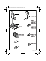
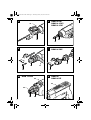
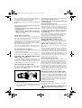
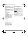
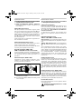
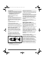
Product Features
The numbering of the product features refers to the
illustration of the machine on the graphics page.
1 Keyless chuck*
2 Front sleeve
3 Rear sleeve
4 Lock-on button for On/Off switch
5 Thumbwheel for speed preselection
(GBM 10-2 RE/GBM 13-2 RE)
6 On/Off switch
7 Rotational direction switch
(GBM 10 RE/GBM 10 SRE/GBM 10-2 RE/
GBM 13-2 RE)
8 Gear selector (GBM 10-2 RE/GBM 13-2/
GBM 13-2 RE)
9 Wing bolt for depth stop adjustment
10 Wing bolt for adjustment of auxiliary handle
11 Auxiliary handle (GBM 13-2/GBM 13-2 RE)
12 Depth stop
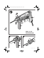
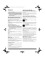
13 Chuck key*
14 Key type drill chuck*
15 Screwdriver bit*
16 Drill spindle with hexagon socket
(GBM 10 RE/GBM 10-2 RE/GBM 13-2 RE)
17 Securing screw for für keyless chuck/key type drill
chuck
18 Open-end spanner**
19 Quick-change adapter (GBM 10 SRE)
20 “Drilling/screwdriving” selector switch
(GBM 10 SRE)
21 Screwing-depth stop (GBM 10 SRE)
22 Adjustment sleeve for screwing-depth stop
(GBM 10 SRE)
23 Belt clip (GBM 10/GBM 10 RE)
*The accessories illustrated or described are not
included as standard delivery.
**Commercially available (not included in the delivery
scope)
Noise/Vibration Information
Measured values determined according to EN 60745.
Typically the A-weighted sound pressure level of the
machine is 77 dB(A). Uncertainty K=3 dB.
The noise level when working can exceed 85 dB(A).
Wear hearing protection!
Overall vibrational values (vector sum of three direc-
tions) determined according to EN 60745:
Drilling in metal: Vibrational emission value
a
h
=7.5 m/s
2
, uncertainty K=2.4 m/s
2
.
The vibration emission level given in
this information sheet has been meas-
ured in accordance with a standardised test given in
EN 60745 and may be used to compare one tool with
another.
The vibration emission level will vary because of the
ways in which a power tool can be used and may
increase above the level given in this information sheet.
This could lead to a significant underestimate of expo-
sure when the tool is used regularly in such a way.
Note: To be accurate, an estimation of the level of
exposure to vibration experienced during a given period
of work should also take into account the times when
the tool is switched off and when it is running but not
actually doing the job. This may significantly reduce the
exposure level over the total working period.
WARNING
OBJ_BUCH-321-001.book Page 16 Thursday, January 25, 2007 8:36 AM

English | 171 609 929 K97 • 25.1.07
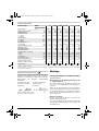
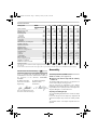
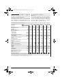
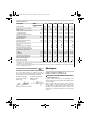
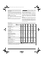
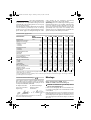
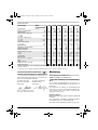
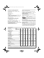
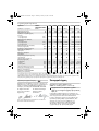
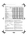
Technical Data
Declaration of Conformity
We declare under our sole responsibility that this prod-
uct is in conformity with the following standards or
standardization documents: EN 60745 according to
the provisions of the directives 89/336/EEC,
98/37/EC.
22.11.2006, Robert Bosch GmbH, Power Tools Division
D-70745 Leinfelden-Echterdingen
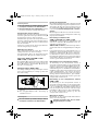
Assembly
Auxiliary Handle (GBM 13-2/
GBM 13-2 RE) (see figure A)
f Operate your machine only with the auxiliary
handle 11.
The auxiliary handle 11 can be set to any position for a
secure and low-fatigue working posture.
Turn the wing bolt for adjustment of the auxiliary
handle 10 in anticlockwise direction and set the auxil-
iary handle 11 to the required position. Then tighten the
wing bolt 10 again in clockwise direction.
Adjusting the Drilling Depth
The required drilling depth X can be set with the depth
stop 12.
Loosen the wing bolt for the depth stop adjustment 9
and insert the depth stop rod into the auxiliary handle
11.
The knurled surface of the depth stop 12 must face
upward.
Rotary drill GBM ...
PROFESSIONAL
10 10 RE 10 SRE 10-2 RE 13-2 13-2 RE
Article number 0 601 ... 135 0.. 135 5.. 137 5.. 168 5.. 169 0.. 169 5..
Rated power input W 450 450 420 500 550 550
Output power W 220 220 220 270 285 285
No-load speed
–1st gear
–2nd gear
rpm
rpm
2000
–
0–2200
–
0–2600
–
0–1150
0–2100
1000
1900
0–1000
0–1900
Rated speed
–1st gear
–2nd gear
rpm
rpm
1300
–
0–1300
–
0–1600
–
0–800
0–1500
550
1000
0–550
0–1000
Rated torque (1st/2nd gear) Nm 6.0/– 6.0/– 6.0/– 9.5/5.0 11.5/6.0 11.5/6.0
Spindle collar dia. mm 43 43 43 43 43 43
Speed preselection – – – z – z
Speed control – z z z – z
Right/left rotation – zzz – z
Maximum drilling diameter
(1st/2nd gear)
–Steel
– Wood
– Aluminium
mm
mm
mm
10/–
25/–
13/–
10/–
25/–
13/–
10/–
25/–
13/–
10/6
25/15
13/8
13/8
32/20
20/12
13/8
32/20
20/12
Max. screw dia. mm––6– – –
Chuck clamping range mm 1–10 1–10 1–10 1–10 1–13 1–13
Weight according to
EPTA-Procedure 01/2003 kg 1.5 1.5 1.5 1.7 1.9 1.9
Protection class /II /II /II /II /II /II
The values given are valid for nominal voltages [U] of 230/240 V. For lower voltage and models for specific countries, these val-
ues can vary.
Please observe the article number on the type plate of your machine. The trade names of the individual machines may vary.
Dr. Egbert Schneider
Senior Vice President
Engineering
Dr. Eckerhard Strötgen
Head of Product
Certification
OBJ_BUCH-321-001.book Page 17 Thursday, January 25, 2007 8:36 AM

18 | English 1 609 929 K97 • 25.1.07
Pull out the depth stop until the distance between the
tip of the drill bit and the tip of the depth stop corre-
spond with the desired drilling depth X.
Retighten the wing bolt for the depth stop adjustment
9 again.
Changing the Tool
f Before any work on the machine itself, pull
the mains plug.
f Wear protective gloves when changing the
tool. The drill chuck can become very hot during
longer work periods.
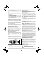
Keyless Chuck (see figure B)
Hold the rear sleeve 3 of the keyless chuck 1 tight and
turn the front sleeve 2 in rotation direction n, until the
tool can be inserted. Insert the tool.
Hold the rear sleeve 3 of the keyless chuck 1 tight and
firmly tighten the front sleeve 2 by hand in rotation
direction o, until the locking action (click) is heard. The
drill chuck is locked automatically.
The locking is released again to remove the tool when
the front sleeve 2 is turned in the opposite direction.
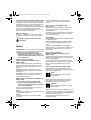
Key Type Drill Chuck (see figure C)
Open the key type drill chuck 14 by turning until the tool
can be inserted. Insert the tool.
Insert the chuck key 13 into the corresponding holes of
the key type drill chuck 14 and clamp the tool uniformly.
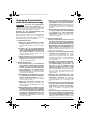
Screwdriver Tools (GBM 10 RE/GBM 10-2 RE/
GBM 13-2 RE) (see figure D)
The drill spindle 16 is equipped with a hexagon socket
for use with screwdriver bits. Dismount the drill chuck
and insert the screwdriver bit 15 directly into the drill
spindle 16 where it is retained by a securing ring.
Quick-change Adapter (GBM 10 SRE)
For quick converting from drilling to screwdriving, the
drill chuck can be removed quickly and easily from the
drill spindle without additional tools.
n Firmly hold the drill chuck and push the red lock
button toward the front.
o Turn the quick-change adapter 19 in the direction
of the arrow shown in the figure and pull it off
toward the front.
Replacing the Drill Chuck
f Before any work on the machine itself, pull
the mains plug.
Removing the Securing Screw
The keyless chuck 1 as well as the key type drill chuck
14 is secured with a securing screw 17 against unin-
tentional loosening from the drill spindle. Completely
open the keyless chuck 1 or the key type drill chuck 14
and unscrew the securing screw 17 in clockwise direc-
tion. Please note that the securing screw has a
left-hand thread.
If the securing screw 17 is seated tightly, apply a screw-
driver to the screw head and loosen the securing screw
by giving a blow onto the handle of the screwdriver.
Dismounting the Key Type Drill Chuck
GBM 10-2 RE/GBM 13-2/GBM 13-2 RE
(see figure E): To dismount the key type drill chuck
14, position an open-end spanner 18 (size 17 mm)
against the spanner flats of the drive spindle.
GBM 10 SRE (see figure F): To dismount the key
type drill chuck 14, firmly hold the quick-change
adapter 19.
Place the machine on a firm surface, e. g. a work bench.
Insert the chuck key 13 into one of the three holes of
the key type drill chuck 14 and loosen the key type drill
chuck 14 with this lever by turning in anticlockwise
direction. A tightly seated key type drill chuck is is loos-
ened with a light blow on the chuck key 13. Remove the
chuck key 13 from the key type drill chuck and com-
pletely unscrew it from the machine.
Dismounting the Keyless Chuck
To remove the keyless chuck 1, clamp an Allen key into
the keyless chuck 1 and position the open-end wrench
18 (size 17) against the spanner flats of the drive spin-
dle. Place the machine on a firm surface, e.g. a work-
bench. Hold the open-end wrench 18 firmly and loosen
the keyless chuck 1 by turning the Allen key in anti-
clockwise direction. A tightly sitting keyless chuck is
loosened with a light blow onto the long end of the
Allen key . Remove the Allen key from the keyless chuck
and completely unscrew it from the machine.
Dismounting the Keyless Chuck (GBM 10 SRE)
To dismount the keyless chuck 1, clamp an Allen key
into the keyless chuck 1. Place the machine on a firm
surface, e. g. a work bench. Hold the Allen key firmly
and loosen the keyless chuck 1 by turning the quick-
change adapter 19 in anticlockwise direction. Remove
the Allen key from the keyless chuck and completely
unscrew the keyless chuck.
Mounting the Drill Chuck
The keyless chuck/key type drill chuck is mounted in
reverse order.
The drill chuck must be tightened with a
tightening torque of approx. 15 Nm.
OBJ_BUCH-321-001.book Page 18 Thursday, January 25, 2007 8:36 AM

English | 191 609 929 K97 • 25.1.07
Operation
Starting Operation
f Observe correct mains voltage! The voltage of
the power source must agree with the voltage
specified on the nameplate of the machine.
Power tools marked with 230 V can also be
operated with 220 V.
Reversing the Rotational Direction (GBM 10 RE/
GBM 10 SRE/GBM 10-2 RE/GBM 13-2 RE)
The rotational direction switch 7 is used to reverse the
rotational direction of the machine. However, this is not
possible with the On/Off switch 6 actuated.
Right rotation: Press the rotational direction switch 7
through to the right stop (for drilling and driving
screws).
Left rotation: Press the rotational direction switch 7
through to the left stop (for loosening and unscrewing
screws and nuts).
Gear Selection, Mechanical
(GBM 10-2 RE/ GBM 13-2/GBM 13-2 RE)
f The gear selector 8 can be actuated at stand-
still or when the machine is running. However,
this should not be done while operating at full
load or maximum speed.
Two speed ranges can be preselected with the gear
selector 8.
Gear I:
Low speed range; for working with large drilling diame-
ter or for driving in screws.
Gear II:
High speed range; for working with small drilling diam-
eter.
If the gear selector 8 cannot be fully engaged, lightly
rotate the drive spindle with the drill bit by twisting the
drill chuck.
Preselecting the Speed (GBM 10-2 RE/
GBM 13-2 RE)
The required speed can be preselected with the
thumbwheel 5 (also while running).
The required speed depends on the material to be
worked and the diameter of the tool. Determine the
optimum setting through practical testing.
Switching On and Off
To start the machine, press the On/Off switch 6 and
keep it depressed.
To lock the pressed On/Off switch 6, press the lock-
on button 4.
To switch off the machine, release the On/Off switch
6 or when it is locked with the lock-on button 4, briefly
press the On/Off switch 6 and then release it.
Adjusting the Speed (GBM 10 RE/
GBM 10 SRE/GBM 10-2 RE/GBM 13-2 RE)
The speed of the switched on power tool can be varia-
bly adjusted, depending on how far the On/Off switch
6 is pressed.
Light pressure on the On/Off switch 6 results in a low
rotational speed. Further pressure on the switch results
in an increase in speed.
Setting the Operating Mode (GBM 10 SRE)
With the “drilling/screwdriving” selector switch 20, it is
possible to select between a permanent and a pres-
sure-dependent connection between the drive and the
drill spindle.
Drilling
Set the selector switch 20 to the “drilling”
symbol.
The drill spindle is permanently connected to the drive.
This setting is suitable for drilling as well as for individ-
ual screwdriving without screwing-depth stop 21.
Screwdriving
Set the selector switch 20 to the “screwdriv-
ing” symbol.
The drill spindle is not engaged until feed pressure is
applied. This setting is suitable for serial screwdriving
with constant screw-in depth in connection with the
depth stop 12 as well as for individual screwdriving
without depth stop 12.
The screwing procedure begins when the applied pres-
sure is high enough.
The selector switch 20 can be felt to engage and can
also be actuated when the machine is running.
If the selector switch 20 cannot be pushed through to
the stop, lightly rotate the drill spindle with the tool bit.
Screwdriving with Screwing-depth Stop
(GBM 10 SRE) (see figure G)
Remove the drill chuck together with the quick-change
adapter 19. Insert a screwdriver bit 15. Slide on the
screwing-depth stop 21 to the stop.
Turning the adjustment sleeve 22 in clockwise direction
results in a greater screw-in depth; turning in anticlock-
wise direction reduces the screw-in depth.
The required setting is best determined by testing.
OBJ_BUCH-321-001.book Page 19 Thursday, January 25, 2007 8:36 AM

20 | English 1 609 929 K97 • 25.1.07
Operating Instructions
f Apply the power tool to the screw/nut only
when it is switched off. Rotating tool inserts can
slip off.
For drilling in metal, use only perfectly sharpened HSS
drill bits (HSS=high-speed steel). The appropriate
quality is guaranteed by the Bosch accessories pro-
gram.
Twist drills from 2.5–10 mm can easily be sharpened
with the drill bit sharpener (see accessories).
We recommend the use of a drill stand (see accesso-
ries) for work where greater precision is particularly
required.
The machine vice, which is available as an accessory,
enables secure clamping of workpieces. This prevents
the workpiece from turning and any accidents this
would cause.
Belt Clip (GBM 10/GBM 10 RE) (see figure H)
With the belt clip 23, the machine can be hung onto a
belt. The user has both hands free and the machine is
always at hand.
Maintenance and Service
Maintenance and Cleaning
f Before any work on the machine itself, pull
the mains plug.
f For safe and proper working, always keep the
machine and ventilation slots clean.
If the machine should fail despite the care taken in man-
ufacturing and testing procedures, repair should be
carried out by an after-sales service centre for Bosch
power tools.
In all correspondence and spare parts order, please
always include the 10-digit article number given on the
type plate of the machine.
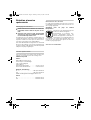
WARNING! Important instructions for connecting
a new 3-pin plug to the 2-wire cable.
The wires in the cable are coloured according to the fol-
lowing code:
Do not connect the blue or brown wire to the earth ter-
minal of the plug.
Important: If for any reason the moulded plug is
removed from the cable of this power tool, it must be
disposed of safely.
Service and Customer Assistance
Exploded views and information on spare parts can be
found under:
www.bosch-pt.com
Great Britain
Robert Bosch Ltd. (B.S.C.)
P.O. Box 98
Broadwater Park
North Orbital Road
Denham-Uxbridge
Middlesex UB 9 5HJ
✆ Service:. . . . . . . . . . . . . . . +44 (0) 18 95 / 83 87 82
✆ Advice line:. . . . . . . . . . . . +44 (0)18 95 / 83 87 91
Fax: . . . . . . . . . . . . . . . . . . . . +44 (0) 18 95 / 83 87 89
Ireland
Origo Ltd.
Unit 23 Magna Drive
Magna Business Park
City West
Dublin 24
✆ Service:. . . . . . . . . . . . . . . . .+353 (0)1 / 4 66 67 00
Fax: . . . . . . . . . . . . . . . . . . . . . .+353 (0)1 / 4 66 68 88
Australia and New Zealand
Robert Bosch Australia Pty. Ltd.
RBAU/SPT
1555 Centre Road
P.O. Box 66
3168 Clayton/Victoria
✆ . . . . . . . . . . . . . . . . . . . . . +61 (0)1 / 3 00 30 70 44
Fax: . . . . . . . . . . . . . . . . . . . . +61 (0)1 / 3 00 30 70 45
www.bosch.com.au
Disposal
The machine, accessories and packaging should be
sorted for environmental-friendly recycling.
Only for EC countries:
Do not dispose of power tools into
household waste!
According the European Guideline
2002/96/EC for Waste Electrical and
Electronic Equipment and its implemen-
tation into national right, power tools
that are no longer usable must be collected separately
and disposed of in an environmentally correct manner.
Subject to change without notice.
OBJ_BUCH-321-001.book Page 20 Thursday, January 25, 2007 8:36 AM
Page is loading ...
Page is loading ...
Page is loading ...
Page is loading ...
Page is loading ...
Page is loading ...
Page is loading ...
Page is loading ...
Page is loading ...
Page is loading ...
Page is loading ...
Page is loading ...
Page is loading ...
Page is loading ...
Page is loading ...
Page is loading ...
Page is loading ...
Page is loading ...
Page is loading ...
Page is loading ...
Page is loading ...
Page is loading ...
Page is loading ...
Page is loading ...
Page is loading ...
Page is loading ...
Page is loading ...
Page is loading ...
Page is loading ...
Page is loading ...
Page is loading ...
Page is loading ...
Page is loading ...
Page is loading ...
Page is loading ...
Page is loading ...
Page is loading ...
Page is loading ...
Page is loading ...
Page is loading ...
Page is loading ...
Page is loading ...
Page is loading ...
Page is loading ...
Page is loading ...
Page is loading ...
Page is loading ...
Page is loading ...
Page is loading ...
Page is loading ...
Page is loading ...
Page is loading ...
Page is loading ...
Page is loading ...
Page is loading ...
Page is loading ...
Page is loading ...
Page is loading ...
Page is loading ...
Page is loading ...
Page is loading ...
Page is loading ...
Page is loading ...
Page is loading ...
Page is loading ...
Page is loading ...
Page is loading ...
Page is loading ...
Page is loading ...
Page is loading ...
Page is loading ...
Page is loading ...
Page is loading ...
Page is loading ...
Page is loading ...
Page is loading ...
Page is loading ...
Page is loading ...
Page is loading ...
Page is loading ...
Page is loading ...
Page is loading ...

Robert Bosch GmbH
Power Tools Division
70745 Leinfelden-Echterdingen
www.bosch-pt.com
1 609 929 K97 (2007.01) O / 103
OBJ_BUCH-321-001.book Page 1 Thursday, January 25, 2007 8:36 AM
-
 1
1
-
 2
2
-
 3
3
-
 4
4
-
 5
5
-
 6
6
-
 7
7
-
 8
8
-
 9
9
-
 10
10
-
 11
11
-
 12
12
-
 13
13
-
 14
14
-
 15
15
-
 16
16
-
 17
17
-
 18
18
-
 19
19
-
 20
20
-
 21
21
-
 22
22
-
 23
23
-
 24
24
-
 25
25
-
 26
26
-
 27
27
-
 28
28
-
 29
29
-
 30
30
-
 31
31
-
 32
32
-
 33
33
-
 34
34
-
 35
35
-
 36
36
-
 37
37
-
 38
38
-
 39
39
-
 40
40
-
 41
41
-
 42
42
-
 43
43
-
 44
44
-
 45
45
-
 46
46
-
 47
47
-
 48
48
-
 49
49
-
 50
50
-
 51
51
-
 52
52
-
 53
53
-
 54
54
-
 55
55
-
 56
56
-
 57
57
-
 58
58
-
 59
59
-
 60
60
-
 61
61
-
 62
62
-
 63
63
-
 64
64
-
 65
65
-
 66
66
-
 67
67
-
 68
68
-
 69
69
-
 70
70
-
 71
71
-
 72
72
-
 73
73
-
 74
74
-
 75
75
-
 76
76
-
 77
77
-
 78
78
-
 79
79
-
 80
80
-
 81
81
-
 82
82
-
 83
83
-
 84
84
-
 85
85
-
 86
86
-
 87
87
-
 88
88
-
 89
89
-
 90
90
-
 91
91
-
 92
92
-
 93
93
-
 94
94
-
 95
95
-
 96
96
-
 97
97
-
 98
98
-
 99
99
-
 100
100
-
 101
101
-
 102
102
-
 103
103


Ask a question and I''ll find the answer in the document
Finding information in a document is now easier with AI
in other languages
- italiano: Bosch GBM Manuale del proprietario
- français: Bosch GBM Le manuel du propriétaire
- español: Bosch GBM El manual del propietario
- Deutsch: Bosch GBM Bedienungsanleitung
- Nederlands: Bosch GBM de handleiding
- português: Bosch GBM Manual do proprietário
- dansk: Bosch GBM Brugervejledning
- Türkçe: Bosch GBM El kitabı
- svenska: Bosch GBM Bruksanvisning
- suomi: Bosch GBM Omistajan opas
Related papers
-
Bosch GSB 16 RE Professional Operating instructions
-
Bosch GBM 13 HRE Operating instructions
-
-
Bosch PSR 14.4 LI-2 Owner's manual
-
Bosch PSR 14,4 LI Owner's manual
-
-
-
-
Bosch GBM 23-2 E Professional Owner's manual
-
Bosch PSR 960 Original Instructions Manual