Page is loading ...

Operating instructions
Hole Locator HL-100
USA

Should you have additional questions concerning thisproduct’ s operation
and use or care and maintance, please call our Customer Service number:
1.800.869.7460 U.S. and Canada
Operating manual:
2
1. Main applications:
USA
The HL 100 hole locator is an easy-to-use point laser for aligning a series of
holes in a straight line. The laser beam serves as a precise horizontal (level),
incline /decline (slope) or vertical (plumb) reference point with a range up to
25m /75 ft.
The HL 100 is specially designed to be installed and self-center itself into the
first drilled hole. Once the laser beam has been aligned, the projected laser
dot serves to mark the drilling position on the next joist / stud.
Horizontal mode (level / slope)
89/16”
51/16”
1
5/8”
311/16”
31/4”
411/16”

2
1
9
5
11
3
(1)
(2)
(3)
(4)
(5)
(6)
(7)
(8)
(9)
(10)
(11)
(12)
(13)
Laser beam emission aperture
ON/OFF switch
Horizontal setting dial (left/right)
Small locking nut for holes from over 7/8” to 3” in diameter (20mm-75mm)
Adapter plate for holes over 3” (75 mm)
Vial for horizontal leveling
Bulls eye vial for vertical leveling
Roll cage stand for vertical operation
Battery compartment cover
Vertical setting dial (up/down)
Large locking nut for holes from 3 1/4” to 4 3/4”in diameter (80mm-120mm)
12
10
8
3
4
13
threaded tube
crosshaires
2. Main components
7
6
5

4
3. Method of operation:
I. Hole diameter ( small / large ) :
The HL 100 can be directly installed in holes from
7
/
8
” to 3” in diameter using
the yellow locking nut (5). The large black locking nut (6) and the adapter
plate (7) are used for larger holes of 3
1
/
4
” to 4
3
/
4
” in diameter. Tighten the
locking nut until the tool is firmly in place. The conical shape centers the
HL 100 in the hole.
II. Material thickness ( min. / max. ) :
The HL 100 can be fixed in materials up to 1
1
/
2
” thickand up to 3” thick for
hole diameters larger than 1
1
/
2
”. By using the large locking nut adapter (6)
as shown below, the HL 100 can be used with materials less then 1
1
/
2
” thick,
such as TJI’s. In this case the distance from the center of the hole to the flange
to should be more than 1
1
/
2
” .
s
3.2. Working in horizontal mode
I. Installing the HL 100:
Lay out the hole location on the first joist / stud. Markand drill required hole
size. Clean away excess wood chips and install HL 100 as described above.
s = max. 3”
3.1. Installation in joists / studs / panels
X = min. 1,5”
X

5
Level
The vial bubble (8) is precisely centered, using the vertical setting dial (3)
II. Aligning the laser dot horizontally (left - right):
Mark the horizontal position on the second joist / stud. (No need to measure
the vertical position). Turn on the laser(2). Dial the laser beam onto the mark
by using the horizontal setting dial (4).
ATTENTION :
To ensure that the HL100 is set up to point in the right direction, it is
important that the lay out and drilling of the first joist/stud , as well as the
horizontal measurement on the second joist/stud is done accurately.
III. Aligning the laser dot vertically (up - down):
Slope
The vial's ring markings (8) allow the laser dot to be adjusted to an inclination,
up or down, of approximately 1% or 2%. Move the vial bubble accordingly by
using the vertical setting dial (3)
∆ = 1 %
ft
∆ = 2 %
1 “
8
ft
1 “
4

6
3.3 Working in Vertical / Plumb mode
I. Mark the desired plumb point with
a cross.
II. Center the HL 100 roughly over the
marked cross, using the cross-
hairs on the back of the unit (12).
III. Center the bulls eye bubble (9) by using both dials, as shown underneath.
The horizontal setting dial (3) allows you to move the bubble sideways;
the vertical setting dial (4) allowsyou to move the bubble back and forth.
IV. Continue to drill
The laser is now correctly aligned.
Drill the second hole by setting the drill bit directly on the center of the laser
dot location. Clear the debris from the hole, if necessary, to allow laser beam
to pass through. The laser dot will now show the correct location of the hole
to be drilled on the third joist / stud. Continue to drill the following joists /
studs by using the center of the laser dot as the exact hole location.
You may prefers to mark the center of the dot with a pencil prior to drilling.
IV. Check the position of the HL 100
over the cross and slightly correct
position if necessary.
The HL 100 is now correctly positioned and plumb, ready to continue.
Drill hole in overhead material using the laser dot to place drill bit, or mark
the dot with a pencil and then drill.

7
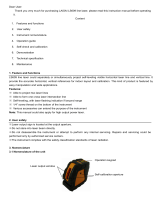
Warning:
This is a class IIIa laser. Do not
look directly into the laser beam !
The goggles supplied with these units
are not safety goggles. They enable
you to see the laser beam more clearly
in bright light conditions.
Keep this product away from children !
The HL 100 has been designed for building site use and leaves our factory
perfectly calibrated. As with any precision instrument, however, its calibration
must be checked regularly. The unit should be checked before starting any
new tasks, particularly when the unit has been exposed to strong vibrations
or after an impact.
The calibration should be checked by using other measuring devices with a
known accuracy ( i.e. spirit level and straight edge for horizontal check, plumb
bomb for vertical check) .
4. Checking the calibration
Unlock the battery compartment
cover (11), fold it backand remove
the batteries. Insert new batteries
correctly aligned, as indicated
shown in the battery compartment.
Only use 1.5V AA size cells
(mignon - LR 6 ) !
5. Replacing the batteries
6. Care and maintenance
The HL 100 laser must be handled carefully, in the same way as any precision
optical instrument.
• Remove the threaded tube (13) by unscrewing ( ccw.) carefully.
• Dirty lens glass in the aperture reduces the beam quality.
It should be cleaned with a soft cloth.
• Clean the laser unit with a damp cloth. Do not spray or immerse the unit!
Do not use solvents or thinners!

Output:
7. Technical data
Adjustment range:
Plumb:
Batteries:
Operating life:
Operating temperature range:
< 5 mW, Laser Class IIIa
This product complies with the applicable
requirements of 21CFR parts 1040.10 and
1040.11.
approx. ± 3°
± 1 mm/m or ±
1
/
8”
over 10 ft
2 x1,5 V alkaline cell, size AA, LR6
Approx. 48 hours
0°C to +50°C or 32°F to +122°F
Subject to technical modifications.
-20 °Cto +60 °C or -4°F to +140°F
Storage temperature range:
8. Guarantee terms and conditions
Stabila provides a guarantee against defects in material and workmanship
for a period of 12 months from date of purchase. Manufactoring defects will
be eliminated atStabila's own discretion either by repairing or replacing the
unit. Stabila accepts no other claims.
No liability is accepted for any faults due to inappropriate treatment (e.g.
damage caused by the unit falling, operation with the wrong voltage or type
of current, use of unsuitable current supply sources) or for any changes made
to the unit by the purchaser or a third party.
Also no claims under guarantee are accepted for natural wear and tear or any
small faults that do not significantly affect the unit's operation.
Any guarantee claims must be made via the dealer. The guarantee form
needs to be filled out if the unit is to be returned.
Laser type: Red diode laser, wavelength 650 nm
Up-right position:
± 0,5 mm/m or ±
1
/
16”
over 10 ft
All moving parts are subject to wear and can be ordered seperately as
spare parts:
(5): Small yellow locking nut
(6): Large blacklocking nut
(7): Adapter plate
(13): threaded tube
9. Spare parts
Accuracy:
Over head position:
± 0,7 mm/m or ±
3
/
32”
over 10 ft
Order No 08 510
Order No 08 520
Order No 08 530
Order No 08 540
8

STABILA Inc.
332 Industrial Drive
South Elgin , IL 60177
1.800.869.7460
www.stabila.com
9
/