Page is loading ...

SUPERSERVER
®
2028R-TXR
USER’S MANUAL
Revision 1.0
Проконсультироваться и купить данное оборудование вы можете в компании «АНД-Системс»
адрес: 125480, г.Москва, ул.Туристская, д.33/1; site: https://andpro.ru тел: +7 (495) 545-4870 email: [email protected]
При обращении используйте промокод AND-PDF и получите скидку.

The information in this User’s Manual has been carefully reviewed and is believed to be accurate.
The vendor assumes no responsibility for any inaccuracies that may be contained in this document,
makes no commitment to update or to keep current the information in this manual, or to notify any
person or organization of the updates. Please Note: For the most up-to-date version of this
manual, please see our website at www.supermicro.com.
Super Micro Computer, Inc. ("Supermicro") reserves the right to make changes to the product
described in this manual at any time and without notice. This product, including software and
documentation, is the property of Supermicro and/or its licensors, and is supplied only under a
license. Any use or reproduction of this product is not allowed, except as expressly permitted by
the terms of said license.
IN NO EVENT WILL SUPERMICRO BE LIABLE FOR DIRECT, INDIRECT, SPECIAL, INCIDENTAL,
SPECULATIVE OR CONSEQUENTIAL DAMAGES ARISING FROM THE USE OR INABILITY TO
USE THIS PRODUCT OR DOCUMENTATION, EVEN IF ADVISED OF THE POSSIBILITY OF
SUCH DAMAGES. IN PARTICULAR, SUPERMICRO SHALL NOT HAVE LIABILITY FOR ANY
HARDWARE, SOFTWARE, OR DATA STORED OR USED WITH THE PRODUCT, INCLUDING THE
COSTS OF REPAIRING, REPLACING, INTEGRATING, INSTALLING OR RECOVERING SUCH
HARDWARE, SOFTWARE, OR DATA.
Any disputes arising between manufacturer and customer shall be governed by the laws of Santa
Clara County in the State of California, USA. The State of California, County of Santa Clara shall
be the exclusive venue for the resolution of any such disputes. Super Micro's total liability for all
claims will not exceed the price paid for the hardware product.
FCC Statement: This equipment has been tested and found to comply with the limits for a Class
A digital device pursuant to Part 15 of the FCC Rules. These limits are designed to provide
reasonable protection against harmful interference when the equipment is operated in a commercial
environment. This equipment generates, uses, and can radiate radio frequency energy and, if not
installed and used in accordance with the manufacturer’s instruction manual, may cause harmful
interference with radio communications. Operation of this equipment in a residential area is likely
to cause harmful interference, in which case you will be required to correct the interference at your
own expense.
California Best Management Practices Regulations for Perchlorate Materials: This Perchlorate
warning applies only to products containing CR (Manganese Dioxide) Lithium coin cells. “Perchlorate
Material-special handling may apply. See www.dtsc.ca.gov/hazardouswaste/perchlorate”
WARNING: Handling of lead solder materials used in this
product may expose you to lead, a chemical known to
the State of California to cause birth defects and other
reproductive harm.
Manual Revision 1.0
Release Date: November 11, 2016
Unless you request and receive written permission from Super Micro Computer, Inc., you may not
copy any part of this document.
Information in this document is subject to change without notice. Other products and companies
referred to herein are trademarks or registered trademarks of their respective companies or mark
holders.
Copyright © 2016 by Super Micro Computer, Inc.
All rights reserved.
Printed in the United States of America

iii
Preface
Preface
About This Manual
This manual is written for professional system integrators and PC technicians. It
provides information for the installation and use of the SuperServers. Installation
and maintenance should be performed by experienced technicians only.

iv
SUPERSERVER 2028R-TXR User's Manual
Contents
Chapter 1 Introduction
1-1 Overview .........................................................................................................1-1
1-2 Serverboard Features .....................................................................................1-1
Processor ........................................................................................................1-2
Memory ...........................................................................................................1-2
Onboard SATA .................................................................................................1-2
PCIe Expansion Slots .....................................................................................1-2
I/O Ports ..........................................................................................................1-2
1-3 Chassis Features ............................................................................................1-3
Hard Drives .....................................................................................................1-3
System Power ................................................................................................. 1-3
Front Control Panel .........................................................................................1-3
Cooling System ............................................................................................... 1-3
Mounting Rails ................................................................................................1-3
1-4 Contacting Supermicro ....................................................................................1-5
1-5 Returning Merchandise for Service.................................................................1-6
Chapter 2 Server Installation
2-1 Unpacking the System ....................................................................................2-1
2-2 Preparing for Setup .........................................................................................2-1
Choosing a Setup Location ............................................................................. 2-1
2-3 Warnings and Precautions .............................................................................. 2-2
Rack Precautions ............................................................................................ 2-2
Server Precautions .......................................................................................... 2-2
Rack Mounting Considerations ....................................................................... 2-3
Ambient Operating Temperature ................................................................ 2-3
Reduced Airfl ow .........................................................................................2-3
Mechanical Loading ................................................................................... 2-3
Circuit Overloading .....................................................................................2-3
Reliable Ground .........................................................................................2-3
2-4 Checking the Setup ......................................................................................... 2-4
Completing the Confi guration ......................................................................... 2-5
2-5 Installing the System into a Rack ...................................................................2-6
Identifying the Sections of the Rack Rails ...................................................... 2-6
Releasing the Inner Rail ................................................................................. 2-7
Installing the Inner Rails on the Chassis ........................................................ 2-8
Installing the Outer Rails onto the Rack ......................................................... 2-9

v
Preface
Sliding the Chassis onto the Rack Rails .......................................................2-10
Chapter 3 System Interface
3-1 Overview .........................................................................................................3-1
3-2 Control Panel Buttons ..................................................................................... 3-2
3-3 Control Panel LEDs ........................................................................................ 3-2
Overheating .....................................................................................................3-3
Responses ..................................................................................................3-3
3-4 Drive Carrier LEDs .......................................................................................... 3-4
3-5 Power Supply LEDs ........................................................................................3-4
Chapter 4 Standardized Warning Statements for AC Systems
4-1 About Standardized Warning Statements .......................................................4-1
Warning Defi nition ...........................................................................................4-1
Installation Instructions ....................................................................................4-4
Circuit Breaker ................................................................................................ 4-5
Power Disconnection Warning ........................................................................ 4-6
Equipment Installation ..................................................................................... 4-8
Restricted Area ................................................................................................ 4-9
Battery Handling ............................................................................................4-10
Redundant Power Supplies ..........................................................................4-12
Backplane Voltage ........................................................................................ 4-13
Comply with Local and National Electrical Codes ........................................ 4-14
Product Disposal ........................................................................................... 4-15
Hot Swap Fan Warning .................................................................................4-16
Power Cable and AC Adapter ......................................................................4-18
Chapter 5 Advanced Serverboard Setup
5-1 Handling the Serverboard ...............................................................................5-1
Precautions .....................................................................................................5-1
Unpacking .......................................................................................................5-1
5-2 Installing the Processor and Heatsink ............................................................5-2
Installing an LGA 2011 Processor ...................................................................5-2
Installing a Passive CPU Heatsink .................................................................5-5
Removing the Passive Heatsink ..................................................................... 5-6
5-3 Connecting Cables ..........................................................................................5-7
Connecting Data Cables .................................................................................5-7
Connecting Power Cables .............................................................................. 5-7
Connecting the Control Panel ......................................................................... 5-7
5-4 I/O Ports ..........................................................................................................5-8
5-5 Installing Memory ............................................................................................ 5-9

vi
SUPERSERVER 2028R-TXR User's Manual
Memory Support ............................................................................................ 5-10
Processor & Memory Module Population Confi guration .......................... 5-10
5-6 Serverboard Details ...................................................................................... 5-12
Serverboard Quick Reference.......................................................................5-13
5-7 Connector Defi nitions .................................................................................... 5-15
5-8 Jumper Settings ............................................................................................5-23
5-9 Onboard Indicators ........................................................................................5-25
5-10 SATA Connections ......................................................................................... 5-26
5-11 Installing Software .........................................................................................5-27
SuperDoctor
®
5 ............................................................................................. 5-28
5-12 Onboard Battery ............................................................................................5-29
Chapter 6 Advanced Chassis Setup
6-1 Static-Sensitive Devices ..................................................................................6-3
Precautions .....................................................................................................6-3
Unpacking .......................................................................................................6-3
6-2 Hard Disk Drives ............................................................................................ 6-3
6-3 Peripheral Drive Installation ............................................................................6-6
6-4 Installing Expansion Cards ............................................................................ 6-7
6-5 Installing the Air Shroud .................................................................................. 6-8
Checking the Air Flow ..................................................................................... 6-8
6-6 System Fans ...................................................................................................6-9
6-7 Installing the Serverboard ..............................................................................6-11
I/O Shield .......................................................................................................6-11
Installing the I/O Shield ..................................................................................6-11
Permanent and Optional Standoffs ...............................................................6-12
6-8 Power Supply ................................................................................................ 6-13
Chapter 7 BIOS
7-1 Introduction ......................................................................................................7-1
Starting BIOS Setup Utility .............................................................................. 7-1
How To Change the Confi guration Data ......................................................... 7-1
Starting the Setup Utility ................................................................................. 7-2
7-2 Main Setup ...................................................................................................... 7-2
7-3 Advanced Setup Confi gurations...................................................................... 7-4
7-4 Event Logs .................................................................................................... 7-32
7-5 IPMI ...............................................................................................................7-34
7-6 Security Settings ...........................................................................................7-36
7-7 Boot Settings .................................................................................................7-39
7-8 Save & Exit ................................................................................................... 7-41

vii
Preface
Appendix A BIOS Error Beep Codes
Appendix B System Specifi cations

viii
SUPERSERVER 2028R-TXR User's Manual
Notes

Chapter 1
Introduction
1-1 Overview
The 2028R-TXR is a high-end server comprised of two main subsystems: the
SC213XAC-R1K05 2U server chassis and the X10DRX serverboard.
Please refer to our website for information on operating systems that have been
certifi ed for use with the system (www.supermicro.com).
In addition to the serverboard and chassis, various hardware components have
been included with the 2028R-TXR, as listed below:
• Four 8-cm system fans (FAN-0174L4)
• One air shroud
• Two 2U passive CPU heatsinks (SNK-P0048PS)
• One rack rail kit (MCP-290-00053-0N)
• SATA accessories:
One HDD backplane (BPN-SAS3-213A)
Sixteen 2.5'' hard disk drive bays (MCP-220-00047-0B)
Note: For your system to work properly, please follow the links below to download
all necessary drivers/utilities and the user’s manual for your server.
• Product manuals: http://www.supermicro.com/support/manuals/
• Product drivers and utilities: ftp://ftp.supermicro.com
• Product safety information:
http://www.supermicro.com/about/policies/safety_information.cfm
For support, email [email protected].
1-2 Serverboard Features
At the heart of the SuperServer 2028R-TXR lies the X10DRX processor serverboard
based upon the Intel PCH C612 chipset. Below are the main features of the
serverboard.
Chapter 1: Introduction
1-1

1-2
SUPERSERVER 2028R-TXR User's Manual
Processor
Each serverboard supports up to two Intel® Xeon® E5-2600 v3/v4 processors in
an LGA 2011 socket (Socket R3). Each processor supports dual full-width Intel
QuickPath Interconnect (QPI) links (of up to 9.6 GT/s one direction per QPI). Refer
to our website for a complete listing of supported processors.
Memory
Each serverboard has 16 DIMM slots that can support up to 2TB ECC 3DS
of Load Reduced (LRDIMM) registered memory or up to 512GB of registered
(RDIMM) DDR4 ECC modules, 2400/2133/1866/1600 MHz.
Note: Refer to Section 5-6 before installing memory and the Supermicro website
for recommended DIMMs.
Onboard SATA
A SATA controller is integrated into the chipset for 10 SATA3 (6Gbps) ports that
supports RAID 0, 1, 5, and 10. The SATA drives are hot-swappable units.
PCIe Expansion Slots
The system has ten low profi le PCIE-E 3.0 x8 and one PCI-E 2.0 x4 (in x8) slots
for a total of eleven PCI expansion slots.
I/O Ports
The rear I/O ports include one COM port, a VGA (monitor) port, two USB 2.0 ports,
two USB 3.0 ports, a dedicated IPMI LAN port and two Gb Ethernet LAN ports.

1-3
Chapter 1: Introduction
1-3 Chassis Features
The following is a general outline of the main features of the SC213XAC-R1K05
server chassis.
Hard Drives
The SC213 chassis includes sixteen 2.5" hard drive bays and one 5.25'' drive bay.
It can accommodate sixteen hot-swap drives. The drives can be hot-swappable if
supported by the operating system. Hard drives must be purchased separately. The
drives are enabled through a backplane.
A slim DVD drive is optional.
System Power
The system includes two redundant hot-plug, high-effi ciency power supplies, each
rated at 1000 Watts.
Front Control Panel
The control panel on the server provides you with system monitoring and control.
LEDs indicate system power, HDD activity, network activity, system information
and power supply failure. A main power button and a system reset button are also
included.
Cooling System
The system supports four fans connected to the motherboard. It also includes
heatsinks for each CPU and a mylar air shroud that directs the airfl ow where cooling
is needed on the serverboard.
Mounting Rails
The system includes a set of quick-release rails, and can be placed in a rack for
secure storage and use.

1-4
SUPERSERVER 2028R-TXR User's Manual
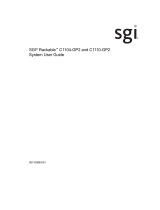
Figure 1-1. Intel C612 Chipset:
System Block Diagram
Note: This is a general block diagram. Please see Chapter 5 for details.
6 PHASE
145W
VR12.5
VCCP0&1 12v
P1
P1
P0
P0
DMIPE1PE2PE3
PE3 PE1PE2
port 4,5(USB2.0)
REAR
#1
#2
A
G
PROCESSOR 1
PROCESSOR 2
#2
#1
DDR4 DIMM
REAR
B
C
D
E
FH
#1
#2
#1
#2
#1
#2 #2
#1
#1
#2
#1
#2
port 1,2(USB3.0)
+
port 0,1(USB2.0)
port 3,4(USB3.0)
+
port 2,3(USB2.0)
port 8,9(USB2.0)
TYPE A
port 5(USB3.0)
+
port 10(USB2.0)
PCIE-3.0 x8 * 5
PCIE-2.0 x4 * 1
x8 * 5
PCIE3.0 x8 Slots [6/7/8/9/10]
PCIE2.0 x8 Slots 11(x4)
CPU REAR
CPU FRONT
QPI
DDR4 DIMM
DDR4 DIMM
DDR4 DIMM
DDR4 DIMM
DDR4 DIMM
DDR4 DIMM
DDR4 DIMM
QPI
9.6GT/s
PCIE3.0 x8 Slots [1/2/3/4/5]
4GB/s
x4
UL1
Dual LAN
I350AM2
JLAN1
RJ45
JLAN2
RJ45
To BMC RMII port
NC-SI
S-SATA0
S-SATA1
S-SATA2
S-SATA3
I-SATA0
I-SATA1
I-SATA2
I-SATA3
I-SATA4
I-SATA5
sSATA Gen3 [0..3]
PET [5,6,7,8]
SATA Gen3 [0..5]
DMI
PCH
PET4
SPI
USB2.0 [0..5]
USB3.0 [1..6]
LPC
USB2.0 [6,7]
NC-SI(RMII)
UL1
BMC
AST2400
HWM
SPI FLASH
16MB BIOS
16MB BMC
SPI FLASH
DDR3
VGA
TPM Header
IPMI LAN
RJ45
PHY
RTL8211E
COM1
HDR 2x5
HDR 2x10
DMI
X10DRX Block Diagram Rev. 1.00

1-5
Chapter 1: Introduction
1-4 Contacting Supermicro
Headquarters
Address: Super Micro Computer, Inc.
980 Rock Ave.
San Jose, CA 95131 U.S.A.
Tel: +1 (408) 503-8000
Fax: +1 (408) 503-8008
Email: [email protected] (General Information)
[email protected] (Technical Support)
Website:
www.supermicro.com
Europe
Address: Super Micro Computer B.V.
Het Sterrenbeeld 28, 5215 ML
's-Hertogenbosch, The Netherlands
Tel: +31 (0) 73-6400390
Fax: +31 (0) 73-6416525
Email: [email protected] (General Information)
[email protected] (Technical Support)
[email protected] (Customer Support)
Website:
www.supermicro.nl
Asia-Pacifi c
Address: Super Micro Computer, Inc.
3F, No. 150, Jian 1st Rd.
Zhonghe Dist., New Taipei City 235
Taiwan (R.O.C)
Tel: +886-(2) 8226-3990
Fax: +886-(2) 8226-3992
Email: [email protected]
Website:
www.supermicro.com.tw

1-6
SUPERSERVER 2028R-TXR User's Manual
1-5 Returning Merchandise for Service
A receipt or copy of your invoice marked with the date of purchase is required before
any warranty service will be rendered. You can obtain service by calling your vendor
for a Returned Merchandise Authorization (RMA) number. When returning to the
manufacturer, the RMA number should be prominently displayed on the outside of
the shipping carton, and mailed prepaid or hand-carried. Shipping and handling
charges will be applied for all orders that must be mailed when service is complete.
For faster service, RMA authorizations may be requested online (http://www.
supermicro.com/support/rma/).
Whenever possible, repack the chassis in the original Supermicro carton, using the
original packaging material. If these are no longer available, be sure to pack the
chassis securely, using packaging material to surround the chassis so that it does
not shift within the carton and become damaged during shipping.
This warranty only covers normal consumer use and does not cover damages
incurred in shipping or from failure due to the alteration, misuse, abuse or improper
maintenance of products.
During the warranty period, contact your distributor fi rst for any product problems.

Chapter 2: Server Installation
2-1
Chapter 2
Server Installation
This chapter outlines the procedure to install your system into a rack. If your system
is not already fully integrated with a drives, processors, or system memory refer to
the relevant chapter for details on installing components.
2-1 Unpacking the System
You should inspect the box in which your server was shipped and note if it was
damaged. If the server itself shows damage, fi le a claim with the carrier.
2-2 Preparing for Setup
Decide on a suitable location for the rack unit that will hold the server. It should be
in a clean, dust-free area that is well ventilated. Avoid areas where heat, electrical
noise and electromagnetic fi elds are generated. It must be near a grounded power
outlet.
The box in which the server was shipped includes two sets of rail assemblies, two
rail mounting brackets and mounting screws to install the system into the rack. The
installation procedure is provided later in this chapter. Please read this section and
"Warnings and Precautions" section before beginning the installation procedure.
Choosing a Setup Location
• Leave enough clearance in front of the rack to enable you to open the front
door completely (~25 inches) and approximately 30 inches of clearance in the
back of the rack to allow for suffi cient airfl ow and ease in servicing.
• This product is for installation only in a Restricted Access Location (dedicated
equipment rooms, service closets and the like).
• This product is not suitable for use with visual display work place devices
acccording to §2 of the German Ordinance for Work with Visual Display Units.

2-2
SUPERSERVER 2028R-TXR User's Manual
2-3 Warnings and Precautions
Rack Precautions
• Ensure that the leveling jacks on the bottom of the rack are fully extended to
the fl oor with the full weight of the rack resting on them.
• In single rack installation, stabilizers should be attached to the rack. In mul-
tiple rack installations, the racks should be coupled together.
• Always make sure the rack is stable before extending a component from the
rack.
• You should extend only one component at a time. Extending two or more
simultaneously may cause the rack to become unstable.
Server Precautions
• Review the electrical and general safety precautions in Chapter 4.
• Determine the placement of each component in the rack before you install the
rails.
• Install the heaviest server components on the bottom of the rack fi rst, and
then work up.
• Use a regulating uninterruptible power supply (UPS) to protect the server from
power surges, voltage spikes and to keep your system operating in case of a
power failure.
• Allow any hot plug drives and power supply modules to cool before touching
them.
• Always keep the rack front door and all panels and components on the serv-
ers closed when not servicing to maintain proper cooling.

Chapter 2: Server Installation
2-3
Rack Mounting Considerations
Ambient Operating Temperature
If installed in a closed or multi-unit rack assembly, the ambient operating tempera-
ture of the rack environment may be greater than the ambient temperature of the
room. Therefore, consideration should be given to installing the equipment in an
environment compatible with the manufacturer’s maximum rated ambient tempera-
ture (Tmra).
Reduced Airfl ow
Equipment should be mounted into a rack so that the amount of airfl ow required
for safe operation is not compromised.
Mechanical Loading
Equipment should be mounted into a rack so that a hazardous condition does not
arise due to uneven mechanical loading.
Circuit Overloading
Consideration should be given to the connection of the equipment to the power
supply circuitry and the effect that any possible overloading of circuits might have
on overcurrent protection and power supply wiring. Appropriate consideration of
equipment nameplate ratings should be used when addressing this concern.
Reliable Ground
A reliable ground must be maintained at all times. To ensure this, the rack itself
should be grounded. Particular attention should be given to power supply connec-
tions other than the direct connections to the branch circuit (i.e. the use of power
strips, etc.).
Warning! To prevent bodily injury when mounting or servicing this unit in a
rack, you must take special precautions to ensure that the system remains
stable. The following guidelines are provided to ensure your safety:
• This unit should be mounted at the bottom of the rack if it is the only unit in
the rack.
• When mounting this unit in a partially fi lled rack, load the rack from the bot-
tom to the top with the heaviest component at the bottom of the rack.
• If the rack is provided with stabilizing devices, install the stabilizers before
mounting or servicing the unit in the rack.
• Slide rail mounted equipment is not to be used as a shelf or a work space.

2-4
SUPERSERVER 2028R-TXR User's Manual
Figure 2-1. Removing the Chassis Cover
2-4 Checking the Setup
Open the unit to make sure the serverboard is properly installed and all the con-
nections have been made.
Removing the Chassis Cover
1. Remove the two screws on each side of the cover, which secure the cover to
the chassis.
2. Press the release tabs to remove the cover from the locked position. Press both
tabs at the same time.
3. Once the top cover is released from the locked position, slide the cover toward
the rear of the chassis and up.
4. Before operating the server for the fi rst time, it is important to remove the
protective fi lm covering the top of the chassis, to allow for proper ventilation
and cooling.
Remove
Screw
Remove
Screw
1
2
1
1
1
1
1
2
1
3
Caution: Except for short periods of time, do not operate the server without the
cover in place. The chassis cover must be in place to allow proper airfl ow and
prevent overheating.Lift the cover off the chassis.

Chapter 2: Server Installation
2-5
Completing the Confi guration
Your server may or may not come with hard disk drives, processors or system
memory already installed. The following sections refer you to the procedures for
installing these components.
Checking the Components and Setup
• To install processors and heatsinks into the serverboard, see Chapter 5 for
the procedure.
• To install system memory DIMMs, refer to Chapter 5.
• To install hard disk drives or optional peripheral drives, see the procedures in
Chapter 6.
• To install expansion cards to the system, see Chapter 6.
Checking the Airfl ow
• Airfl ow is provided by three 8-cm chassis cooling fans. The system compo-
nent layout was carefully designed to direct suffi cient cooling airfl ow to the
components that generate the most heat.
• To install the air shroud that assists with air fl ow, see Chapter 6.
• Make sure all power and data cables are properly connected and not blocking
the chassis airfl ow. Also make sure that no cables are positioned in front of
the fans.
Providing Power
After installing or checking components and mounting your server in its rack, con-
nect the power.
1. Plug the power cords from the power supply units into a high-quality power strip
that offers protection from electrical noise and power surges. It is recommended
that you use an uninterruptible power supply (UPS).
2. Depress the power button on the front of the chassis.

2-6
SUPERSERVER 2028R-TXR User's Manual
2-5 Installing the System into a Rack
This section provides information on installing the chassis into a rack unit with the
rails provided. There are a variety of rack units on the market, which may mean
that the assembly procedure will differ slightly from the instructions provided. You
should also refer to the installation instructions that came with the rack unit you are
using. Note: This rail will fi t a rack between 26.5" and 36.4" deep.
Identifying the Sections of the Rack Rails
The chassis package includes two rail assemblies. Each assembly consists of three
sections: An inner rail that secures directly to the chassis, an outer rail that secures
to the rack, and a middle rail which extends from the outer rail. These assemblies
are specifi cally designed for the left and right side of the chassis.
Figure 2-2. Identifying the Outer Rail, Middle Rail and Inner Rail
(Left Rail Assembly Shown)
Inner Rail
Rail Assembly
(Shown with Rails
Retracted)
This Side Faces
Outward
Locking Tab
Middle Rail
Outer Rail
/