Page is loading ...

OWIIER
GUIDE
OP[RATION
.
IIAI}ITTIIA}I(T
.
PARTS
1I'T
EATON'S
tKt
l_
5 H.P.
DEIUXE
OUTBOARD
TOTOR
MODEL
5D11V
:'Jt$S&sq$N
HORSEPOWER
NUMBER
OF CYLINDERS
BORE AND STROKE
PISTON
DISPLACEMENT
SPEED
CONTROL
FUEL.
TANK CAPACITY
RUI{NIN(] TIMF
(FULL'
STAFITER
GEARSHIFT
CONTROL
SPECIFICATIONS
5.0 AT 4OOO R.P.M.
O.B.C.
CERTIFIED
r 1s 16" BoRE X
1 1
2', STROKE
8.84 GUBIC
INCHES
2 CYCLE. 2
PORT.
ALTERNAI-E FIRING
2
BLADE, 8" DIAMETER X 7 I
4''
PITCH
RUBBER BLADE
COMBINATION DISPLACEMENT
AND
CENTRIFUGAL WATER PUMP
BUILT IN FLYWHEEL
MAGNETO
.
VARIABLE
VENTURI
SYNCHRONIZED
SPARK
AND THROTTLE.
TWIS'I- GRIP CONTROL
THROTTLE)
WEIGHT
RECOMMET'IDED
TRANSJOM
I IF IGH'I
SPEED
(AVERAGE
BOATS)
Monulocf
ured
expressly
SPARK
AND THROTTLE.
. .OTGALLONS
.
APPROX.
I
HOUR
AUTOMATIC
REWIND
NEUTRAL
REVERSE
49 POUNDS
.
15"
2 TO 12
MPH
".OT.
EATON
C?,",,,O
Outboard
lTlarine
hrporotion
of
Cono/o
ltd
gtltlNOl0UCll
-
(AIADA
402 r7
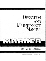
3

CUIAWAY
YltW
0t 5 H0RSEP0I'IJIR fn0DEt
STARTER
STARTER
HOUSING
HANDLE
IDLE
ADJUSTMENT SCREW
CARBURETOR
CARBURETOR
ADJUSTMENT KNOB
SPEED
CONTROL GRIP
STEERING
HANDLE
STERN BRACKET
CLAMP
SCREW
ANGLE ADJUSTMENT
LEVER
REVERSE LOCK
LEVER
WATER
TUBE
DRIVE
SHAFT
WATER
PUMP
SHOCK
ABSORBER
PINION GEAR
FUEL TANK
CAP
-FUEL
TANK
FLYWHEEL AND
ARMATURE PLATE
CONNECTING
ROD
SPARK PLUGS
CYLINDER
PISTON
CRANKSHAFT
CONTROL CABLE
UPPER SHIFT ROD
EXHAUST RELIEF OUTLET
EXHAUST HOUSING
SHIFT ROD
CONNECTOR
LOWER SHIFT ROD
UNDERWATER
EXHAUST OUTLET
WATER INLET
(FoRwARo
oPERATToN)
PROPELLER
CAP
PROPELLER
SHAFT
ITARBOARO
(nIGHT),
poRT
(LEFT)
ARE
DEgIGNATEO WXtLE".FACING
AOW
BEVEL GEARS
Figure
I
PROPELLER
DRIVE
PIN

FOREWORD
You are
to
be
congratulated
on
your
selection
of
this
outboard
motor whlch will
give
you
years
of satisfactory
service. The fine
materials
and high standards
of workmanship
used in
the manufacture
of
this
motor assure
you
of durability and
lasting
performance.
Read
through this manual
carefully before
operating the motor.
You will find
complete
operating
instructions
and
recommendations
for
the
care
and
protection
of
your
motor.
Extend
the
same
care
to
this motor
you
would
give
to
a
new
automobile
or
other
personal
property
of
even
less value
and
it
will
be
a constant
source
of satisfaction
to
you.
Care in
handling
will
prevent
scratches
.and
nicks
which
will
mar the
appearance.
The
operating
instructions
are concise and
easy to follow,
even
for
the beginner.
But
if
you
have
never
operated an
outboard
motor,
it
witl be
helpful to
practice
the
step by step
procedure
a
few times before
putting
the motor
in actual
opera-
tlon.
Outboarding
is
great
sport.
Always
remember, however,
that
you
have friends
on
the
water. Extend
to
them the courtesy
of thoughtful,
safe
operation
of
your
motor
and boat and
you
will increase
your
own enjoyment.
ATTACHING
MOTOR
TO
BOAT
ANGLE
ADJUSTING
BOLT
KEEL
IOO
CUT
OFF
MAXIMUM
.
TRANSOM
THICKNESS
1
*3/4"
f
I
I
VERTICAL
TRANSOM
HEIGHT FROM
BOAT
BOTTOM
This
motor
is designed
for use
on a standard 15-inch
transom. If transom
is higher,
it should be
cut
down to 15
inches so
propeller
will be at
least 2
inches below
bottom
of boat. Best
performance
will
be obtained
by having
the driveshaft
vertical to boat
travel and the
propeller
placed
below
bottom
of
the
boat
(see
Figure
2). Performance
can often be
im-
proved
by
cutting
off the keel at a 10" angle
as illus-
trated. This
will
prevent
formation
of spray and
provide
free running
performance.
Place
motor on stern
of boat with stern
bracket
clamps
inside the stern,
centered
on
the
transom
or
stern board. Tighten
bracket
clamp screws securely
by hand.
CAUTION
When
motor is running,
occasionally
check
bracket
clamp screws
to be sure
they
are
tight. We
will
not be responsible for
any
motor damaged
or lost overboard due
to
loose
clamp screws.
The
use of a saJetv
chain
or
rope attached
to nrotor
stern bracket safety
chain link
(item
1, Figure'
5)
and
boat will
guard
against loss of motor
overboard.
Holes are
provided
in thumb screw handles through
which a
padlock
may
be appl.ied to lock the motor
on
the boat.
't
r20 ANGLE
Figure
2

OPERATIO}I
OF YOUR IUIOTOR
ANGLE
ADJUSTMENT
A simple means
is
provided
for adjusting
the motor
to
a
vertical
position
.to
make allowance
for angle
of the
transom.
To
accomplish
this
adjustment,
tilt the motorslightly
(gear
shift
lever must beinFORWARDoTNEUTRAL),
then liJt up on angle
adjustment
lever
(see
item
5,
Figure
5)
and
move it ahead or
back in the slots
in
the
stbrn bracket
so that motor is
in
a vertical
posi-
tion
when
lower unit
rests
against
thelever.
Onsome
boats it may
be necessary to correct
angle adjust-
ment to maintain
motor
in
a vertical
position
when
changing
load from one
to more
passengers.
Always
try to arrange
load so boat
runs
on an
even
keel.
Transom
(stern)
angles
may vary somewhat;
how-
ever, range of adjustment is sufficient
to accommo-
date angles found irr most
boats.
MAXIMUM
PERFORMANCE
Figure
3
GEAR SHIFT
The
motor is equipped
with
gear
shlft control to
provide
operation of the motor in
Forward, Neutral,
or
Reverse
by means of a
gearshift
lever
(Figure
4)
Iocated on side
of motor below the tank. Move the
lever
as far
as
possible
toward front
of
tank for
"Forward"
motion of boat
--
toward rear of tank as
far as
possible
for
"Reverse"
motion of boat.
The
intermediate
position
is
"Neutral"
or out of
gear.
When
motor is not running the internal
gear
shift mech-
anism may be
in
such a
position
that
gear
shift lever
cannot
be moved
from
"Neutral"
into
"Forward"
or
"Reverse"
---
DO
NOT FORCE.
This may be reme-
died
by
pulling
on the
starter cord with throttle control
at
STOP to turn
gears
slightly
until the
gear
shift lever
will
move to desired
position.
Extreme
care
should
be taken
to
prevent
bending or striking
the
lever.
2
REVERSE
Always
retard
motor speed to START
position
of
throttle control
or
slower before shifting. A special
reverse
lock
(item
4, Figure 5) built into the swivel
bracket locks the
motor against tilting
when
in
re-
verse. Use extra care
when running in
reverse to
avoid striking
any
obstruction
and damaging lower
unit
parts.
The tilting feature functions only irr
FORWARD
or
NEUTRAL
gear
shift
position.
LUBRICATION
AND
FUEL INSTRUCTIONS
Proper
lubrication is
an
important
factor in the
per-
formance
anci life of
your
outboard motor.
The
following
instructions are therefore very
important
and should
be followed carefully.
The
oil and
fuel mixture referred to in the
following
instructions
should always be thoroughly mixed in
a
separate
container before
pouring
into
motor fuel
tanK: NEVER POUR
SEPARATELY
INTO
FUEL
TANK. AIso, all fuel should be
poured
through
a
fine mesh strainer
to remove dirt and water which
may be
present.
Use only metal
containers.
TYPE
OF
GASOLINE.
Use
a
good grade
of
regular
gasoline.
TYPE
OF OIL.
See back cover
of
this manual for
correct oil
specifications.
MD(T{JRE.
Mix
l/2
pint
oi oil
with each
gallon
of
gasoline.
PROCEDURE.
Pour into the container
approximately
one-half the amount oI
gasoline
required.
Add
all
the oil required at the ratio
of.
l/2
pint
of oil
to
each
gallon
of
gasoline.
Shake the two together until they
are thoroughly mixed.
Add
the balance of
gasoline.
Shake
container briskly to insure mixing.
LUBRICATION
OF GEAR CASE.
The
gear
case has
been filled
at
the
factory with the correct lubricant.
Check for lubricant after
first
5
hours
of
operation;
then
every
50 hours.
For
method of lubrication,
see
page
5.
For
type of lubrication, see
back cover.
TQUI
PMENT
NECESSARY
WHEN
OUTBOARDING
Although the following articles may not al-
ways
be
needed, it
is
advisable to have them
aboard when motoring.
1.
An
extra can of
fuel,
properly
mixed.
2.
Funnel
with strainer.
3.
Tools.
4.
Starting
cord.
5. Rope or chain
to tie
motor to boat.
6.
Extra spark
plug.
?. Oars and all other equipment
required by
law
when outboarding in
Federal waters.

BREAK-
IN
PER
IOD
Reasonable
care in the
operation
of
the
motor
during
the first
several hours
of use
will
improve
its
per-
formance
and
insure ionger
life.
Folloq/
the fuel
and
lui.lrication
instructions
carefully. After
operating
motor
at
part
throttle for
aboui Jne hour, it is
per-
missible to run
at full throttle for
a
few secclnds
fol-
lowed
by a few
minutes of
part
throttle
operation.
Repeat
frequently,
gradually
increasing the
time of
full throttle
until another two
hours of operation are
completed. No extra
oil
is required
for the break-in
period.
STARTING INSTRUCTIONS
(See
Figure 4.
)
1. Open air vent
screw
in fuel tank filler
cap.
2. Open fuel tank shut-off valve.
3.
Move
gear
shift
lever to NEUTRAL
position.
4. Place
speed control
grip
on steering
handle to
START
position"
5.
Turn carburetor
knob
to left or PRIME
position
and hold down against spring
pressurefor
10
seconds,
then release.
6. PulI starter
handle slowly until starter
engages,
then
pull
forcibly. If
motor does not start
a-fter
several
pulls
on starter
cord,
repeatpriminginstruc-
tions.
(Allow
starter cord to
rewind
before releasing
handle.
Also, do not
pull
cord
out
more than 30
inches.
)
?. After
motor
starts,
turn
carburetor
knob
slowly
to the right
until
motor runs
smoothly, It is
advisa-
ble to turn speed control
grip
toward
SLOW to avoid
excessive
idling speed
aJter carburetor is
adjusted.
Allow
motor to operate
at
SLOW
until
ready
to
put
the boat
into
motion.
Operolion
of
your
flotor
8. Shift
to
FORWARD
or
REVERSE
as desired.
Move
gear
shift
lever
quickly
into desired
position.
DO NOT ease
into
position.
IMPORTANT
Since this
motor can
be
operated
in FOR-
WARD,
NEUTRAL or REVERSE by merely
using the
gear
shift
provided
it is very
IM-
PORTANT that the speed control
grip
is
ai-
ways moved within the SHIFT RANGE
(as
in-
dicated
on
the
steering
handle)
before shifting.
9.
WHEN IN FORWARD ON[,Y,
advance speed
control
to FAST
position.
Rurr motor a
Iew
minutes to
warm up. Turn
carburetor
knob to left
or
right
until smoothest running
is
obtained.
Slow speed
needle is
pre-set
at the
factory for
average
use.
For
adjustment,
see
"Carburetor
Adjustments,
"
page
4.
10. Turning speed
control
grip
on steering handle to
FAST increases
speed and
to
SLOW decreasesspeed.
11. To stop
motor
turn speed control
grip
to STOP
position.
WARM
MOTOR
It is not
necessary to
prime
motor when
starting
if
motor
has
been
warmed up.
Motor can usually be
started
with carburetor
knob
in running
position
and
pulling
starter
handle
with
speed control
lever
at
START
position.
FLOOD ING
Flooding
may occur
by
over'.priming
or
priming
a
warm
motor. If this occurs. turn carburetor
knob
to extreme
right
(off
position)
and
pull
starter handle
several tirnes. Wtren motor starts, allow
to run
until
it stops.
Then
follow instructions for starting
cold
or warm motor, whichever applies.
STARTER
HANDLE
SPEED CONTROL

Operof
ion
of
ycur
fUlotor
CARBURFTOR ADJUSTMENT
The carburetor is
adjusted for
both high
and low
speed
operation at the factory.
If
further adjustment
is necessary
proceed
as follows:
With
port
motor
cover removed,
start motor
aspreviouslyinstructed,
set gear
shift
lever in FORWARD
and
operate at
FAST,
adjust
carburetor
knob
until motor runs
smoothly. Now
move speed
control
grip
to SLOW.
Turn
Iow speed
adjusting screw, located
on right
hand
side
of carburetor
(item
2, Figure
8) toward
RICH or LEAN
untll
satisfactory
low speed
per-
formance is
obtained.
NOTE
Turning
low speed
adjusting screw
or car-
buretor
knob
to the left
enriches the
mixture,
that is increases
the
ratio
of
fuel
to
air.
Turning
to the right leans
the mixture reduc-
ing the ratio
of fuel to air. A rich
mixture
may
cause motor to
run
"rough" and
a
lean
mixture is indicated
by
"coughing
or
spitting"
in
the carburetor.
The
carburetor
is
now adjusted for
average
condi-
tions.
Special setting may
be necessary
for best
performance
with heavy boat loads or
very slow
trolling.
CO-P ILOT
The
co-pilot
permits
the
motor to maintain
a set
course
without
holding
steering
handle. It can be
adjusted
by
tightening
the screw, located
in
the cen-
ter
of the
pivot
bearing
(item
2, Figure
5) to the
de-
sired tension.
TILTING
OF MOTOR
The tilting
feature
is
designed to
permit
self tilting
when striking
any
submerged
object while
running
in
forward
position.
Care,
however, should be
taken
in
obstructed waters, not to operate motor
at
too
high a
speed. This tilting feature is
also useful in
boat
Iaunching,
beaching
or
rowing in shallow
waters.
To tilt
the motor,
grasp
the
carrying handle and rear
of
gas
tank
and
pull
the motor toward
you.
The
motor
can be
tilted
only
when
gear
shift
Iever
is in
FORWARD
or
NEUTRAL
position.
Never try to tilt
motor
by bearing down on steering
handle.
TILTING
FRICTION
Proper
tilting friction is
set at factory, but
through
continued use, friction
may have to be adjusted.
To
adjust, loosen or
draw up on tilting
bolt nut
(itern
6.
Figure
5) as
required,
using a wrench.
Tension
of tilt need not
be too
great,
but
just
suffi-
cient to maintain the motor in
any
position
of
tilt.
EMERGENCY STARTING
In
case of starter
failure.
vou
can
still
use
vour
motor.
Remove two rear
starter housing screws
and
two
long front
screws
attaching
starter
housing and
fuel
tank to bracket. Lift
off entire
starter
housing
assembly. Replace front screws to
secure tank.
To
start motor, wind a 3/L6
inch rope,
with
a
knot
in
one end
placeo
in
the notch
on the
{lywheel
pulley,
clockwise on the
pulley
on top
rim
of flywheel
(Fig-
ure
6).
When
reassembling
the starter housing assembly,
set
in
position
and
start
the
mounting screws. Holding
starter in
position, pull
handle
-.lovly
until
starter
engages.
Tighten
screws and again check
engage-
nent.
I
SAFETY
LINK
2
CO-P|LOT
SCREW
3
CLAMP
SCREW
4
REVERSE
LOCK LEVER
5 ANGLE ADJUSTMENT
LEVER
6 TILTING BOLT NUT
Figure

CARI
OT
YOUR
IIIOTOR
)ROPELLER
Motors
are
equipped with a
propeller
which
gives
the
best all around
performance
on the
average boat.
Adding
a high
speed
propeller
to
a
motor
will not
increase the speed
of the boat
unless the
boat
itself
is light
and designed to
develop higher speed.
We
cannot be responsible
for
wear
or
damage to a
motor
used
for racing
or equipped
with
a racing
propeller.
SHOCK ABSORBIR
The
shock
absorber assembly
(item
35,
page
14)
consists
of a comparatively strong
spring
inserted
tightly
into
a
retainer
and
pilot.
The
retainer is
locked to
upper driveshaft
and
pilot
pinned
to lower
driveshaJt. Action
of
the
slip
clutch assembly is
such that
when
the
propeller
strikes
an underwater
obstruction
the
spring is
caused to
coil
slightly
in
either the retainer
or
pilot,
or
in
both, releasing
its
grip,
thereby
absorbing
shock
of sudden impact.
PROPELLER DR IVE P iN
Should
the
propeller
strike an underwater obstructlon
forcibly, the
propeller
drive
pin
may
shear. This
should
rarely,
if
ever,
occur, because
of
the shock
absorber. TURN OFF MOTOR
IMMEDIATELY. Re-
move rubber
cap. Remove broken
pin
by driving
parts
out with a
punch.
Examine
propeller.
A
blow
forceful enough to
shear the drive
pin
may also have
damaged the
propeller
seriously. Propellershouldbe
replaced i-f badly damaged.
Drlve
a new
pin
lnplace,
securilg
propeller
to the
shaft.
Replace rubbercap.
REMOVING MOTOR FROM BOAT
At
end of
run,
wlth motor
runnlng in NEUTRAL,
close fuel shut-off
valve
and
permit
motor torununtil
it stops,
draining
carburetor.
Close
airvent screw
in filler
cap.
The
motor
can then
be carried
with-
out fuel leakage. For
safety,
always drain fuel
tank
before transporting
motor. Also
drain
water
thoroughly
as
in
"Care
of Motor in
Cold Weather.
"
When removing
motor Irom
boat, lift
motor
in
a
straight
upward
position
and hold this
position
for
a
brief
period
until
all water is
drained from the
underwater
exhaust
tube
and
water cooling system.
Do
not
stand motor
on top
or carry
with the top
down
before
draining
water, as this
may allow
water to
enter
the
power
head from
underwater
exhaust tube.
CARE OF MOTOR IN COLD WEATHER
The
motor
will not lreeze
while
in
use, but
when
it
is
idle,
water
in
the
cylinders or
pump
might freeze
and
damage
the motor.
Drain
by
setting
the motor in
an
upright
position
and
pulling
starter
cord several
times
with
speed
control
grip
in STOP
position.
If
the
motor is to be stored
during cold
weather, be
sure
that no
water
is
left in
the motor
or
it
mav
freeze.
(See
"Preparation for Storage.
")
SALT
WATER
INSTRUCTIONS
When
using
a
motor in
salt
water
it
should
be
re-
moved
from the
boat
when not in service.
Flush the
motor thoroughly either by running
it
in
a tank
of
fresh
water or by
removing
WATER FLUSH
plug
(Figure
?)
and using
an
adapter
(available
through
your
regular
Service Parts Source),
run
fresh
water
through
cooling
system.
Avoid excesslve
pressure
which might
damage
gaskets.
Wipe the motor dry
and
go
oyer all
parts
with an
oily cloth.
This should
be
done as soon
as
possible
a-fter
removing motor
from
boat.
GTAR LI.'BR ICATION
Where
a complete change
of
lubricant is required,
remove both the
fill and
drain
plugs
(Figure
?)
with
motor in
upright
position.
Drain out all of the oil
,
water, or residue, replace
the drain
plug,
then fill
the
gear
case through the fili
ptrug
with a
pump
type
oil can. Replace
plug.
See
back cover of
this
manual for specifications
of
correct
gear
lubricant. In
case of emergency
it
is
permissible
to
use S.A.E. 30 oil
,
but oniy until such
time
as the
proper
lubricant can be
obtained.
The
gear
case should be
checked
for
presence
of
water at
frequent
intervals. When checking. the
motor
must
have been
idle
for some time to allow
oil
and water
to separate. To
check.
remove the oil
fill
plug
and loosen the
oil drain
plug partly
to alkrw
enough of
the lubricant to
drain out
to
determint:
whether or
not
water
is
present.
U no watel
is
present
the drain
plu€i
may be retightened
without
excessive loss
of
lubricant. Be sure to
refill
the
gear
case to the
fill
plug
level. lf
water
is
present
drain
gear
case
and
refill. AJter running motor for
several hours, again check for water. if
presence
of
water
persists.
have seals in
sear ca.se checked"
BY-PASS COVER
WATER
INLET

(ore
olyourfflofor
GREASI
NG
There is a Zerk
type
grease
fitting on the motor
which
should
be
greased
occasionally.
This
fitting
is located
on
the
end
of the
gear
shift lever shaft
on
the
starboard side. A
good grade
of waterproof
grease
such as
Lubriplate
No. 930AA
is recommended
for
this fitting.
COOLING
SYSTEM
Water
for
coollng
purposes
ls
provlded
by actlon
of
the single
stage rubber
impeller centrtfugal
pump
located
between
the upper
and lower houelng
of
the
lower
unit. This
functions
as a displacement
pump
at
slow motor
speeds
and as a centrifugal
pump
during
operation
in the higher
speed
range. There
are two
water
lnlets in the
gear
case.
Durtng
FORWARD
operatlon
of the
motor,
water enters
the
slot, equipped
with a screen,
located
directly
below
exhaust
outlet, and is forced
through the coollng sys-
tem,
later to be
discharged at the outlet
in
the
ex-
haust tube
provided
for thls
purpose.
Water
enters
t}te
coollng system through
the holes
ln the water
by-pass
cover
above
the anti-cavltatlon
plate
when
operatlng
in
REVER.SE.
(See
Ftgure
1 for locations
of
cooling
system
parts.)
NOTE
If,
whlle
operatlng motor at full
speed, lt
should
show eigns
of slowtng down,
lmmedl-
ately check water dlscharge
at water
outlet
(Figure
?) located
at rear
of
the motor di-
rectly
below cyllnder. In
case no water is
being
dtscharged,
lmmediately shut
off the
motor
and
check
water
lnlet
(Figure
?) for
obstruction. If no
obstructlon
is found, it
may
lndicate worn
pump
parts.
PREPARATION
FOR
STORAGE
No
outboard
motor
should be
placed
in
storage with-
out considering
the necessary
precautlone.
Remove
all
plugs
in the
gear
case and drlveshaft
housing,
marked DRAIN, FILL
and WATER
FLUSH
(Ftgure
7)
to allow water
ln the
gear
case and
water
remalning
in the
coollng system
to draln
off.
To
male certaln
all water has
been dralned, rock
motor from
side
to
slde, If
operated
in salt water, flush
cooling system
with
fresh water.
Refill
gear
case with
gear
lubrlcant.
Remove
spark
pluge
-
pour
about a tablespoon of
clean oll through
each spark
plug
openlng. Turn
fly-
wheel slowly
to dlstrlbute
oll on cyllnder walls. R€-
place
spark
plugs.
Draln all
fuel from tank,
ga.s
line and
carburetor.
Under no
circurnstances should
tle motor
be stored
ln an inverted
posltion.
It
should
be
hung
on
a rack
slmilar to the manner
in
which
it is mounted on the
boat. Store
ln
a dry
place.
Wrap the
motor in a
ptece
of canvas, old blanket,
or
heavy
paper.
PUTTING MOTOR
IN
USE
AFTER
SIORAGE
Pull
off spark
plug
leads
and
remove
spark
plugs.
If
rubber spark
plug
hoods have
been
removed
from
lgnitton leads, be sure
to
ground
leads
to some
part
of motor to
prevent possibility
of
Bpark.
(THIS
IS
IMPORTANT.) Spin
motor by
pulltng
on starter cord
to
remove
excess
oil from
cylinders.
Clean
spark
plugs,
check
gap
and replace.
Install
new
plugs
if
they are cracked, broken,
or
badly burned. Tlghten
all screws and nuts.
Check adjustments such as tllt-
ing
frictton, co-piloi, and
carburetor
knob.
S.PARK
PLUG
The
correct spark
plug gap
i6 .030 tnch.
Plugs
are
set
properly
at the factory and
are
right
when
the
motor
is
recelved. We recommend
Champlon J6J
or
Auto
Lite
A3X
spark
pluge,
or equivalent
for re-
placement.
Keep
the
sparli
plug
cables free
from
oll and do not
permlt
them to become frayed or
broken.
Clean
the spark
plugs pertodically
and
re-
set to the
proper gap
settlng. Be sure
gaskets
are
intact. For
accesa to spark
plugs,
remove
port
motor
cover.
RUNNING MOTOR
IN TEST TANK
1. Do not
run motor out of water.
2. Do not
"break-ln"
motor
ln tank.
3.
Remoye
water by-pass
cover
(small
metal strip
on lower
port
stde of upper
pumF
houslng,
Ftgure
7).
4. When runnlng
tn
tank
be sure
gear
houslng
and
propeller
are
submerged.
5.
Do not
race motor in tank.
6.
Use test
propeller
when testlng motor
ln
tank.
?. Cavttation
(air
pocket
around
propeller)
mryoccur
when operating
motor
ln
tank wlth regular
propeller.
Motor
will then not
perform
properly
or it may
race
and be damaged as a result.

MOTORS THAT HAVE BEEN SUBMERGED
Precaution
should
be
taken to
prevent
a motor
going
overboard
(see
page
1). However,
if a motor has
been submerged, lt should be recovered
as
quickly
as
possible.
Since
the motor
ls temporarily out of lvorklng
order,
do not
attempt to operate it until
the
following
pro-
cedure
has
been used to restore
lt to
service.
1. Drain
fuel tank by removing fuel
tank filler cap
and turning motor
upside
down.
2. Remove
plug
at
very
bottom of carburetor(item6,
Figure 11) thereby
draining water and
fuel from car-
buretor. Pour enough
fresh
fuel
into
gas
tank to
re-
move any water f
rom
fuel line, by
permitting
fuel to
run
out
of
carburetor drain
plug
hole
(fuel
tank shut-
off valve should be open). When all traces
of water
are
removed, replace
plug.
3.
Remove
and
dry spark
plugs.
If
r'ubber
spark
plug
hoods have been removed,
be sure to
ground
wires
somewhere
on motor. Lay motor down
on
gear
shift handle side and
crank motor. Turn motor
so that spark
plug
holes
are down and again crank
motor
until no further water
is
expelled.
4. Check
spark by lnserting
screw or other
small
metal obJect into rubber spark
plug
hood to make
contact wlth
terminal sprlng in hood
and
holding
screw about 1/4
inch from
cyllnder and cranking
motor rapldly. Check
spark from both leadwires.
If rubber hoods
are not
.on
leadwlres,
be sure to
ground
one lead while checking
the other.
5.
Replace
all
parts
removed,
ftll tank with new fuel
mixture,
and start motor. It may
be necessary to
clean water
from
points
of spark
plugs
several
tlmes
as there
is a
possibility
of
small drops
of $'ater
re-
maining
in the
cyllnder whlch may
short the
pLugs.
The
above lnstructlons are
prlmarlly
for
motors that
have
been submerged
in
fresh
water. For
motors
submerged
in salt \{ater a few
addltlonel
precautions,
listed below,
may be necessary.
1. Remove
carburetor
and fuel tank,
and
wash
with
fresh
water. Dry
thoroughly.
2. Remove
flywheel,
and wash magneto wlth
fresh
water.
3.
It is advisable
to wash
external worklng
parts,
such
as the starter
mechanism,
with fresh water
and lubrlcate. Internal
working
parts
are lubricated
by the fuel rrrixture.
If
motor wlll
rrot
operate after the
above instructions
have
been followed,
disassemble
and
wlpe all
parts
dry.
Coat with
oil to
prevent
rust and followinstruc-
tions under
"How
to Obtatn Servlce."
(See
back
cover.)
Core of
your
llllotor
It
may be
""""u"'lA:)3"1""',,,
to inspect the
magneto. If so, it is necessary to remove the
gas
tank and flywheel. However,
if cleaning or
adjusting
of
points
only is
required,
remove the starter hous-
lng,
(see
page 4,
"Emergency
Starting") and
the three
screws
releasing
the starter ratchet and flywheel
cover.
Access
to the
points
for cleaning
or
adjustlng
ls
possible
through the
opening on
the
top of the
flywheel.
HOW
TO REMOVT
FLYWHEEL
Disconnect
fuel line and remove fuel tank.
Use
fly-
wheel
puller
lf available. If not, hoLd flywheel rigid
and unscrew
the
flywheel
nut about
two
full
turns.
Have
someone
lift up on the flywheel
anti then
place
a
piece
of bar solder
or a block of lead over
the
fly-
wheel nut
and tap a sharp blow with a hammer. If
flywheel does
not come off
,
loosen nut a trifle more
and
repeat
procedure.
When fiywheel comes off
,
use care
not to Iose
key
by
which llywheel is heid in engagement
with
shalit. When
again
replacing
flywheel, be sure
key
is in
piace
and
fits
snugly, then
draw
up nut
as
tight as
possible.
IMPORTANT: Tapers
on
fiywheel
and cranksha,ft
must
be
perfectly
clean and dry
before reassembling.
MAGNETO LUBRICATION
The
magneto is equipled with a felt
oiler to lubricate
t}te cam and reduce wear
on the cam block
of the
breaker
(Figure
9).
A
few drops
of
ligtrt
oil
should
be
put
on
the felt
once or twice
a
year.
BREAKER ARM
BREAKER POINTS
BREAKER ADJUSTING SCREW
CONDENSER
BREAKER BASE SCREW
COIL
AND
LAMINATION
ASSEMBLY
BREAKER
CAM
FELT
OILER

Core of
your
Molor
CHECKING
BREAKER
POINT GAP
CLEAN AND ADJUST BREAKER POINTS
AJter removing starter ratchet and flywheel cover,
revolve flywheel until
opening
is directly over
breaker
(there
are two
breakers
on
this magaeto).
Carefully spread
points
with small screwdriver.
Insert
point
dresser.
(Sarrdpaper,
fine coil
iile, nail
file, etc.
NEVER
USE
EMERY CLOTH.)
Release
points,
work dresser up
and
down to smooth.
FoIIow
same
procedure
with
piece
of thick smooth
paper
to
remove
traces of
foreign
particles
which
might be
Ieft on
points.
After
cleaning,
reset
polnt gap
to
.020
inch maxi-
mum
opening
as follows: When
hole
tn
flywheel is
directly over the brealer, maximum opening
of the
breaker is obtained. Check
with
.020 inch
feeler
gage.
If
opening
is
under
or over
.020
inch
loosen
breaker
plate
screw
(item
5,
Figure
9) slightly.
Turn
adjusting screw
(item
3,
Figure
9) to right or
Ieft until requlred
setting
is obtained.
Tighten
breaker
plate
screw and
re-check
with
gage.
See
figure 10.
CAR
BURETOR
It
is irnportant that the carburetor
be
kept
clean.
Dirt,
sediment or water may accumulate in it
and
cause hard starting or irregular
performarce.
To clean the carburetor and reed valves, disconnect
the fuel line,
and remove nuts and screws which
attach
the
carburetor
to the
crankcase.
Remove
the
carburetor carefully to
prevent
damage to the
gasket
between crankcase and carburetor. If the
easket
is
damaged, replace it with a new
one.
Check
the
reed
valves carefully
for dirt between the
reeds
and
reed
plate,
or
for damaged reeds.
Re-
move the float bowl drain
plug.
Remove
the
float
bowl
cover.
Flush
out the
float bowl
and
entire
carburetor with a
good
solvent.
Remove
adjusting
needle
and
blow
out
fuel
passage
with compressed
air
.
(See
item
8,
Figure
11 .
)
B
ADJUSTING BREAKER
POINT GAP
Reassemble
and install
the
carburetor on
the motor
with exception of carburetor
knob and
primer
cam.
Be
sure
gasket
is in
good
condition
and is in
place
to form an alr tight seal.
It ls necessary to
make
initlal
adjustment oI
the
adjustlng needle before installing
carburetor
knob
or
fastening
primer
cam to adjusting
needle.
Turn
adjusting
needle ln
(cLockwise)
with
screwdriver
until
seated
(DO
NOT
FORCE). Then
back out
(coun-
terclockwlse) one-half
turn.
Slip
primer
cam on
adJusting needle
leaving 1/16 inch clearance
between
it
and
prlmer
lever.
Point
prlrner
cam
up and
tighten set screw.
Replace motor covers
and
fasten
carburetor
knob to adjusting
needle
with
arrow
pointing
straight up.
Refer
to
Low Speed adjustment on
Page
4
for
final
adjustment of Iow speed
adjusting screw.
The
preceding
instr:uctions
also apply in the
event
the
adjusting screw is
removed to
replace
packing,
CARBURTTOR
ADJUSTI NG
NEEDLE FR
ICTION
Should
the
carburetor adjusting
needle become
so
loose
that the carburetor
knob will
not remain in a
set
position,
it
can be tightened
by drawing
down on
the
packing
nut
(jtem
?,
page
10).
NOTE
Turn carburetor knob to
"Prime"
position
when
tightening
packing
nut to
preverrt
damage
to needle seat.
If
tightening of
the
packing
nut will
not
help, it may
be necessary to
replace
the
packing.
To replace
packing,
remove the carburetor
knob, motor covers,
primer
cam,
adjusting needle,
packing
nut,
washer,
packing
and spacer. Install
new
packing
and reas-
semble.
Be
sure
all
of
otd
packing
is
removed be-
fore inserting
new.

Core of
your
tolor
I
2
3
4
5
BOWL COVER 6
ORAIN
PLUG
PRIMER
LEVER
7 FUEL INLET NIPPLE
THROTTLE LEVER
8 ADJUSTING NEEDLE
CONTROL KNOB 9 FLOAT BOWL
PRIMER
CI\M
IO
UPPER
REED
11 LOWER REED
e/r".h el4anf
This chart
wlll
provlde
u outline
for
systematic tracing oI operating difficulties.
The causes
lloted are thos€ which the average
omer
cM locate with
little
diffi-
culty.
Once
you
have located the cause, the remedy is usuatly self-evident.
If laulty motor
operatlon camot be traced to any of the causes listed, we
re-
commend
that
you
see your
dealer.
AlEys make sure
that
you
have
been
using the correct
gasoline-oil
mirture,
and
are following operating
instructions accurately.
Spaik
plugs
are one of
the most common
sources
of trouble. It may save con-
siderable
time lf
spark
plugs,
then the other ignitlon
parts,
are checked flrst.
MOTOR \flLL
NOT STANT
FUEL, TIIOUBLE
'f
an-k empty.
Shut-olf valve closed.
Filler
cap
vent closed.
Water in carburetor,
tank or stralner.
Carburetor
nozzle or
passages
clogged.
Strainer
screen between shut-olf
valve and
tank clogged.
Fuel line clogged.
Inproper fuel and oil mtxtur€.
NO SPARK TO PLUG
gas
Lead to spark
plug
disconnected
or
grouded
Rrea.ker
potnts
not set at
.020
inch
gap.
Breaker
points
corroded.
Loose or
broken
wire tn
magneto.
NO COMPRESSION
Leaking
fasket
or stuck reed valve.
SPARK PLUG
TROUBLE
Fouled.
Porcelain
cracked.
Center
electrode
(pole)
Ioose.
Pointa
not set at
.030
tnch
gap
MOTOR KNOCKS
Flywheel hub loose.
Flywheel nut loose.
Incorrect spark
plug pre-lgnlting.
MOTOR IS STIFT
AND CRANXS HARD
No lubrlcut ln
gear
case.
WATER
STOPS
CIRCULATING
I
Clogged Eter
pump
lnlet,
I
Gear housing not settlng
deep enough
ln
Fter
MOTOR
RUNS
BUT
PROPELLER
DOES NOT TURN
Drtve pin
sheared.
M TON WILL NOT
IDLE
Carburetor
not adiusted
properly.
Improp€r
gasoline
and oll
mlxture.
Throttle stuck open.
Dirty or
defective spark
plug.
Clogged
carburetor.
IDproperly
set breaker
points.
MOTOR MISSES
WIRINC
Loose or broken ignttlon wire.
B.oken
or oil-soaled iNulatlon on wlre.
MAGNETO
weak
or broken breaker
point
spring.
Corroded or
dlrty
brealer
points.
Brealer
potnts
not set
at
.020 tnch.
CANBURETOR
Nozzle or feed hole
dirty.
Water or {ureign matter in
strainer.
Carburetor
passages
clogged.
MOTOR LOSES POWER
INCORRECT
FUEL MIKTURE
Too rich
-
motor slows dos and four cycles
(fires
€very
other
compression stroke).
Too lean
-
motor
slows doM and
Inay
back fire.
MOTOR VIBRATES
Faulty lgnition
or carburetion.
Loose
ptvot
bearing.
Bent
or broken
propeller
blade or motor loose
on
boat.
MOTOR
RUNS
BUT
BOAT MAKES LITTLE OR
NO
PROCRESS
Badly
bent
propeller
blades.
Weeds or
rope wound around
propeller.
Rope or oth€r obstruction
dragging in mter.
I

CARBURITOR
Repoir
Forfs
Iist
l
I
I
l
%
./'o
16
g#r-
W--,,--''
T
sn
32
30
3r
19
20
2L
22
23
24
25
26
27
28
29
30
31
32
33
34
35
36
l7
23
\u
lt:
9,A'
a_--J
27-7
2
I
,*-za
,*ffi
,t(
29' i
'7c@>
,/
5
,//
//
//
I
-ry
Part
No.
Ref
No
rl
2l
Description
Carburetor Assembly
-
Complete
.
Screw
-
Carburetor Knotr
.
Knob
-
Carburetor
Control
.
.
Screw
-
Set
.
Cam
-
Primer
.
Spring
-
Primer Lever
.
Lever
-
Primer
.
Gland
Needle
-
Adjusting
Washer
-
High Speea Neeiie
.
Packing
-
Adjusting
Needle
Spacer
-
High
Speed
Needle
Spring
Pin
-
Cotter
Lever
-
Throttle
Lug
-
Spring Holding
Screw
Screw
-
Adjusting
Plate
-
Friction,
Carb. Adi.
.
Part
No.
1'
Description
Cover
-
Valve
Valve
-
Throttle
PIW
-
Strainer
Gasket
-
PIug
Screw
Cover
-
Bowl
Needie
-
InLet
Float
Assembly
.
.
Screw
-
Float
.
Pin
-
Cotter,
Float
Lock
-
Float
Screw
Plate
-
Binding,
Reed
Reed
-
Upper
Spacer
Reed
-
Lower
Nipple
Carburetor
Body and Nozzle
551 517
552410
1 33384
55001 5
551
988
551068
1 32691
5524L7
I1551953
10
t550259
11
1551954
12
1550405
13
1551149
l4
1551251
15
1550564
16
1302227
i
17
1550280
I
,1fu**
502?6
50275
1 3 3487
1?1 318
2227
50805
3
4
5
o
d
B
1 323 51
591 1 88
3-34
3-15
1 2081 3
1312 56
550263
5502?1
550262
1
3492
1 394
t0
Assembly

ll
Repoir
Ports Iist
fiIAGil
EIO
p:-:'
q-\'r-0ll
vli
I
€*-i:
[----
-2s
*N
\/
WAV
13
w+-
-y';-----
-
' \la
21
?
33
^-32i
N-\\
36
I
?e
?!-$wFALy
"
ru
\=a
,-
23
24
25
26
27
28
6@
-
I
i
I
I
t---
lnei
i
No.
///\
to\
tt{tr,<
r r--_-toj
fi=="-lt
B
-'0
Description
Sleeve
-
Insulating
Marker
-
Upper
Lead
High Tension Lead
Assembly
-
Upper
.
Cover
-
Rubber,
Sparkplug
.
Terminal
-
Spring, Lead.
High Tension
Lead Assembly
-
Lower
(Also
Includes
26 and
z7)..
Coil and
Lamination
Assembly
Screw
-
Breaker
Mounting
Washer
-
Bow.
Breaker Assembly
.
CIip
-
Spring
.
Rocker
Arm Assembly
.
.
CIip
-
Breaker
Spring
.
Breaker Base
Assembly
Screw
-
Eccentric
Screw
-
Condenser
Mounting
Condenser
.
Wick
-
Oiler
Clip
-
Oiler
.
Armature Plate
and
Post
Assembly
t6g
12---'
Part
No.
3038
52
510233
1 20?83
591436
5L0232
510231
59143?
510189
1.
510188
t.
l
5801 1 8
510278
l.
510208
I
580148
l.
?1-1052
i.
580123
|
510204
I.
580122
1.
510185
l.
5101e3
|
5101?3
l.
29
30
31
32
33
34
35
36
3?
38
39
40
41
Description
Screw
-
Ratchet
to
Flywheel
Ratchet
-
Starter
Cover
-
Inspection HoIe
Nut
-
Flywheel
FIywheeI
Cam
-
Magneto
Screw
-
Armature
Plate Mtg
Washer
-
Lock
jScrew
-
Armature
Plate Mtg
lScrew
-
Cam
to
Plate
?l Washer
-
Lock
lCam
-
Throttle
jScrew
-
Clamp to
PuIIey
Clamp
-
Leads
to
PuIIey
lScrew
-
Pulley
to
Armature
I Piate
iScrew
-
Pulley
to
Armature
i
Plate
iscrew
-
Cable
to
Pulley
lWasher
-
Cable to PuLley Screw
iCable
-
Throttle
Control
lPulley
-
Armature
Plate
1
Armature
Plate
Assembly
l.
Screw
-
Lamination
Mtg
i
.
Screw
-
Breaker
Termlnal
.
|
302468
izo2rrr
l3o324e
1301e88
I
5801
07
I
5101 68
1510192
13x28
1510191
l?1x?65
l?1x148
15523e1
1302?
51
i5523?2
l1
31024
I
lrozar
z
1
3
A
!
5
6
t
8
q
10
11
t2
1a
L4
15
16
L7
18
19
2Q
2t
22
38
51
2366
3?1
183
1019
5
10194
580121

TIAilIFOTD
&
BRACKET
--26
-"t
?la
-r,
77
-@---28
30
-31
i5
toffitt
B3-.-.f,11 '\\ltv-
1;ffill fl
;-fl
lffi
I
rffiW-7?i*E4
Repoir
Ports
Iist
:jJffiW'ii,ik>'--#TM':
w"'i
1\
ffi li i
L-t[,;"(
/
\wrr 3-&
1ru
:i
f-'-'H$,
V
*hT\'iryr
54.-
'yr=
-\t
h\zo|lt-{
i
--\\JY
\
58
\
67
'S'l

Repair Ports Iisl
IUIANIFOI.D & BRACKET
Ref,
No.
Part
lilo.
Description
Ref
No.
Part
No. Description
1
.,
q
+
D
6
4
I
8
a
10
11
L2
13
L4
15
16
tl
18
19
20
2l
22
23
24
25
26
2'I
28
29
32
33
34
35
30
31
36
en
3B
39
40
I
302681
I
I
|
552361
I
5e1452
302?10
301 6
56
552209
203260
1 33452
303078
303093
300346
303252
3?
597?
302717
3027t2
303094
303096
303079
?1-1352
3001 B1
552369
552377
3031 07
591
3??
7
-31
7
-221
71-?65
7L-L487
552403
550348
552399
552400
302342
303? 1 5
t91
374
303
1
91
303236
303864
t5-26B
303
3
54
301915
Screw
-
Exhaust
Housing
Cover
PIate
Plate
-
Exhaust
l{oustng
Cover
Steering Handle
Assembly
.
Screw
-
Steering
Handle Grip
.
Spring
-
Twist
Grip
.
Grip
-
Steering
Handle
.
Plate
-
Steering
Handle
.
Screw
-
Steering
Handle
Halves
.
Screw
-
Steering
Handle
HaIves
.
Handle
-
Steering
(Inner
HaU)
.
Pin
-
Groove,
Gear
and
Shaft
.
Washer
-
Handle
to Spring
.
Gear
and ShaJt Assembly
-
Long
.
.
Bushing
-
Steering
Handle
.
Washer
-
Steering
Handle
.
Handle
-
Steering
(Outer
HalI)
Cover
-
Steering
Handle
Gears .
Washer
-
Steering
Bracket
to
HandIe
Screw
-
Pulley
to
Shaft
Screw
-
Clamp to Pulley
Clamp
-
Cable
to
Lower Pulley.
Pulley
-
Throttle
Control,
Lower
Washer
-
Pulley
Gear
and
Shaft
Assembly
-
Short
.
Screw
-
Exhaust
Tube
to
Powerhead
Washer
-
Lock
Screw
-
Exhaust
Tube
Top
Cover Plate
Washer
-
Lock
Gasket
-
Lower Bearing
to
Lower
Unit.
Gasket
-
Cover
Plate
to
Powerhead
Plate
-
Cover. Exhaust
Tube
Top.
Gasket
-
Cover Plate
to Exhaust
Tube
Screw
-
Lever
to Shaft
Washer
-
Lever
to Shaft Screw
Shift Lever
and ShaIt Assembly
"O"
Ring
-
Shaft
to Exhaust
Tube
Spring
-
Shift
Lever
Washer
-
Shift
Lever
Shaft
Pin
-
Cotter,
Shift Rod
Lever
-
Shaft
to
Shift
Rod
Sleeve
-
Reverse
Lock
46
47
72
?3
74
?5
76
77
?8
79
80
B1
82
83
4T
42
43
44
45
50
51
52
53
54
DJ
56
DI
58
59
60
61
62
63
64
65
66
48
49
70
7t
6?
6B
69
552362
30191 3
552376
552360
2t-276
1
-227
591
3?6
552365
303049
303436
552363
r7
-t82
25-196
302051
303349
2026t7
160084
303396
20202L
591 3?5
301983
376081
375744
302420
41
-48
376082
591451
303850
552368
13-558
120052
25-238
L9-t24
552393
552392
55240L
552387
5523?0
552386
5523?3
552364
27
-283
27
-284
591381
Spring
-
Shift
Rod
.
Sleeve
-
Shift
Rod
Rod
-
Shift
(Upper)
Gronrmet
-
Upper Shift Rod
Seal
Screw
-
Steering
Bracket to
Exhaust Tube
Washer
-
Lock
Steering Bracket
and
Bushing
Assembly.
Spring
-
Reverse
Lock
Pin
-
Cotter,
Reverse Lock
Rod
Rod
-
Reverse Lock
Lever
-
Reverse Locking
Nut
-
Tilting BoIt
Washer
-
Tilting Bolt
Nut
Spring
-
Tilting
Bolt
Bolt
-
TiltinC
Shim
-
Stern Bracket
to
Swlvel
Bracket
BaIl
-
Stern
Bracket to Swivel
Bracket
Screw
-
Stern Bracket
Spring
-
Tilting Lever
Tilting Lever Assembly
Washer
-
Conical
Stern Bracket
Assembly
-
Port
.
Clamp Screw Assembly
.
Retainer
-
Swivel
Plate
.
Plate
-
Swivel
Clamp
Screw
Stern Bracket
Assembly
-
Starboard
(Also
Includes Items
63,
64,
65).
.
.
SwiveI
Bracket Assembly
.
Screw
-
Co-pilot
.
Spring
-
Co-pilot
Screw
.
Screw
-
Swivel
Bracket
Halves,
Rear
.
Washer
-
Lock
.
Screw
-
Swivel Bracket
llalves.
Front
.
Washer
-
Lock
.
Bracket
-
Swivel,
Starboa.rd
.
Bracket
-
Swivel, Port
.
Washer
-
Thrust
Absorber
-
Shock,
Upper
Absorber
-
Shock, Lower
Plate
-
Co-pilot
Tube
-
Water
Grommet
-
Water T\rbe, Upper.
Plug
-
Water Flush
Washer
-
Flush Plug
Housing
-
Exhaust
l3

Repoir
Porls List
ffiI
60
40
45
17
44
=-t'
*--'
ort.
o
l/,/
q
,,.1e
/a]:
Lafl{DJ-))
\ffi..fi
g
GTAR CAST
54 56
55
53
I \\^\
Nl
";1"ryi:
w
-
@'"u'
o-
25
tf
r.P@q{
----lb

Repuir
Ports Iisl
GEAR
(ASE
:f P""t
'i
*"'
|
302325
I
sorzss
Description
Screw
-
Exhaust
Tube
to
Gearcase
Screw
-
Shift
Rod
Connector
. .
Washer
-
Connector Screw
Connector
-
Shift Rod
.
Cap
-
Propeller
.
Pin
-
Cotter, Propeller
Shaft.
Pin
-
Drive
Propeller
and Bushing
Assembly
Pin
-
Shifting
Lever Pivot
Washer
-
Pivot
Pin
Screw
-
Lower
to Upper
Gearcase
Screw
-
Grease Plug
(Drain)
Washer
-
Grease Plug
(Drain)
SeaI
-
Upper
to
Lower
Gearcase
Pin
-
Dowel
Pin
-
Cotter, Pivot Pin
.
Pin
-
Shift Rod
Lever
-
Shifter
Cradle
-
Shifter
Bearing
-
Front, Gearcase
Seal
-
Gearcase
Head
,
"O"
Ring
-
Gearcase Head
Gearcase
Head and Bearing
Assembly
Bushing
-
Rear
Reversing
Gear
Gear
-
Rear
Reversing
Washer
-
Thrust
Clutch Dog
Shifter Assembly
Shaft
-
Propeller
Gear
and
Bushing
Assembly
-
Front
Pinion
3-156
303466
303?00
552375
3
760?3
Description
Screw
-
Detent Spring
Sp.ring
-
Detent
Spring
-
Backup,
Detent Spring
Shift
Rod
-
Lower
Pinion
Shaft
and
Shock
Absorber
Pilot
Assembly
Key
-
Pinion
to
Pinion Shzrlt
Washer
-
Lower
Bearing SeaI
Spri.ng
-
Lower
Bearing
Seal
Washer
-
Spring Retaining
Pin
-
Drive
Screw
-
Impeller
Housing
Gromnret
-
Water Tube,
Lower
Housing
-
Impeller
Impeller
and
Insert
Assembly
Pin
-
Irnpeller
to Drive Shaft
.
Plate
-
Impeller Housing
Drive Shalt
Seal
-
Bearing
Housing
Bearing
Housing
and Bearing
Assembly.
Gasket
*
Bearing
Housing
to
Gearcase
Bushing
-
Shift Rod,
Lower
.
"O"
Ring
-
ShiJt
Rod
Screw
-
By-pass
Cover
Cover
-
Water By-pass
Screw
-
Grease
Plug, Fill
Washer
-
Grease
Plug.
PIug
-
Water Intake Screen
Screen
-
Water Intake
Gearcase
Assembly
(A-lso
Includes Items
12, 13, 14,
15,
51,
52,55, and
56)
"O"
Ring
-
Seal, Driveshaft
2
3
4
302290
303794
303365
13-332
302333
591
389
303358
304083
0?1
b
J
8
I
10
11
l2
13
t4
15
16
t7
1B
19
20
zl
22
23
-283
..284
303 328
30061 1
301912
302 504
303340
3381
3380
3345
1
-135
552465
30335?
303327
303261
303395
302497
303442
277L9L
3007?1
3033?6
5524,L4
300599
3?60?4
303339
303332
301 877
302681
303344
27
-283
27
-284
300314
303 331
376060
303 34?
360
?6069
24
25
26
27
28
29
30
03998
04010
03361
60?8
43
345
ive
Shaft
Dr
31
32
33
34
35
36
37
38
39
40
41
42
43
44
45
46
47
4B
49
50
51
52
53
54
55
56
5?
5B
DY
l5

Description
3027
54
303905
552397
JJL
5YO
302824
Bolt
-
FueI Tank
to
Cylinder
Screw
-
Carburetor and
Bracket
to Crankcase
.
Bracket
-
FueI
Tank
Mounting,
Starboard
Bracket
-
Fuel Tank Mtg.,
Port
Screw
-
Clamp
I
10
11
L2
13
L4
15
16
t7
18
19
20
2t
22
23
24
25
26
27
28
29
30
31
32
33
34
35
552404
3008? 5
552379
302658
L32823
5523?8
41
-163
552405
302659
4t-223
302599
302580
302442
7
-46
t5-254
552062
5501 09
200322
376290
591 393
5501 16
1
-333
120110
5-21
75327
1 20395
7
-86
14
50
POWER
HEAD
Repoir
Porfs Iist
g------15
?8
2
-W
/l
37
t9
'.-'--3
t\
\21
Clamp
-
H. T. Leadsto Cylinder
CIip
-
E.T.
Leads
PuIIey
-
Throttle Control
Idler,
Upper.
Shaft
-
Idler Pulley, Upper
Screw
-
Pulley
Bracket
to Cylinder
Bracket
-
Idler Pulley, Upper
Pin
-Cotter,
Lowerldler PuIIey
Shaft
-
Lower ldler Pulley
Pulley
-
Throttle
Control
Idler,
Lower
Screw
-
Support
Plate
.
Plate
-
Armature
Support
Washer
-
Wave
Ring
-
Retaining
Nut
-
Cylinder
to
Crankcase
Washer
-
Lock
Nut
-
Carburetor
to
Crankcase
Screw
-
Carburetor to Crankcase
Gasket
-
Carburetor.
Spark
Plug
(Champion
J6J)
Spark
Plug
(Auto
Lite A3X)
.
Cylinder
and
Cover
Assembly
Gasket
-
Cylinder to Crankcase
Ring
-
Piston
Clip
-
Ring, Piston
Wrist
Pin
Pin
-
Piston
Wrist
Piston
and
Dowel PinAssemblv
ting
Rod Assembly.
Key
-
Crankshalt
Screw
-
Lower
Crankshaft
Bearing
SeaI
-
Lower Bearing to
Drive Shaft
Lower
Crankshaft
Bearing and
Drain Tube Assemblv
-@g-'
0-t'
41
,/l
t3
a\
t\
I
@i
w.
,,--'35
34/
\i
\
FJ
€_---.---gg
550037
71
-1550
550063
550062
590035
552474
550947
4t-362
591396
Gasket
-
Lower Bearing
to
Crankcase
Screw
-
Crankcase to
Center
Bearing
:'
Dowel
-
Locating
Screw
-
Center
Bearing
Center
Bearing
Assembly
(Includes
Item 39)
rankshaft
Retainer
-
Oil
Slinger
-
Oil
Crankcase
Assembly
5-E
;-fr
l--__.
fi
,ryw
,-g
%'o-r,
[=_rn
PM
//
27//
30
3(
)-g-\
l6

//-'
Repoir
Ports Iist
TRIIII
GROUP
2l
\
231
g-=--3
Part
No.
Part
No.
59I378
\5246
I
zoz9
rz
552395
552224
552424
5524t5
5524r9
zo3290
552394
5521
t
I
5 5219
9
552398
59 1 398
591454
59
I 380
t
71 118
5907
t- 4
))r40J
I
2
3
4
5
6
7
8
I
10
11
L2
13
L4
15
16
L7
18
19
20
2l
22
23
24
25
26
27
28
29
30
zI-167
152389
59t453
r3l99t
13-5r
20235(
27664.;
z0zt55
zozIt4
30z2zz
302
r04
7t-t026
z023
1 7
20217
0
59r214
55 I ZO5
J\ ), LZt)
304097
376377
304099
+r-t97
Descriptlon
Screw
-
Starter
to
Tank
Screw
-
Starter
to Bracket
Starter
Assembly
-
Complete
.
.
Screw
-
Hub
to
Housing
Washer
-
Lock
Washer
-
Starter
Spindle
Spindle
and Ptn Assembly
Spring
-
Pawl
Cup
-
Equalizer
Spring
-
Friction
Screw
-
Retainer
Washer
-
Lock
Retainer
-
Starter
Pawl
Pawl
-
Starter.
Clamp
and
Screw
-
Rope
Clamp
-
Rope
Ilandle
-
Starter
Rope
-
Starter
Starter
Pulley
and Pln
Assembly
.
Pin
-
RoIl,
Starter
Pulley
Spring
-
Starter
31
32
33
34
35
36
rtl
38
39
Description
.
Starter
Housing
Assembly
Screw
-
Knob
to Valve
Ihob
-
Shut
Off
Valve
Shroud
Assembly
-
Starboard
.
Screw
-
Shroud,
Front
.
Screw
-
Shroud,
Rearw
-
vru
vsu,
rtc4l
|.
Screw
-
Applique
to
Shroud
.
Applique
-
Starboard
Bumper
-
Shroud
Shroud
Assembly
-
Port
.
Applique
-
Port
Clamp
-
Hose
Hose
-
Shut
Off Valve
io
Carburetor
Valve
-
Shut
Off
FueI Tank
Assembly
"
Screen
and
Connector
Assembly
.
Gasket
-
Tank Ou0et
.
Filler
Cap Assembly
.
Gasket
-
Filler
Cap
35
4
26
FStt
$:ii
W::
@--"7.

1
How
To
Obtain
Service
U
your Ull(ll{G
motor
refrrses
to operate
or
per-
form
properly
and
no
lnstructions
in
this
book
cover
the
probable
cause
of
failure,
please
follow
this
procedure.
1.
Take
your
Yll(lllc
motor
to a local
outboard
motor
service
statlon.
Most
service
and
repair
work
can be
handled
locallY.
2.
U no
local
service
ls
avallable,
contact
the
con-
cern
from
which
you
purchased your motor statlng
type of
failure,
date of
purchase,
model
number,
motor
serial
number,
and
horsepower.
Do not
return
motor
to the
f actorY.
WABNANTY
VIKING
oUTBOA,RD
MOTOR
\T
We
warrant each
new outboard
motor to
be free from
defects ln material
and workmanship
under normal
use and
when
operated
according
to
these
lnstructions.
Within 90
days f rom
date
d
sale to the
ortglnal
purchaser
we wlll
exchange
free of
charge any
part
whlch our
exemination
shall dis-
close
to be
defective.
This warranty
shall
not
apply to
anymotor whlchhas
been subject
to mis-
use,
alteration,
or accident;
or
whlch has
been used
for raclng or equlpped
w'ith a
racing
Propeller.
AII transportatlon
charges on
motors
or
parts
returned
to
us
must
be
prepaid.
EATON'S
OF
CANADA
il
:'l
f,ow
To 0rder
Repair
Parts
This
book
gives
you
a complete
repalr
parts
list
for
your
outboard
motor. Should
you
need
to order
repair
parts,
they
may be obtained
direct
from the
concern
from
which
you
purchased
your motor '
If
you
order
repalr
parts
the
following
information
is
needed
to fill
your
orders
properly:
1.
Part number
and
description
of
part
as shown
ln this
catalog.
2. Complete
motor
model
number
and
serial
number .
These
numbers
wlll
be found
stamped
on
the in-
structlon
plate
located on
the
front of
the stern
bracket.
Do
not order
parts
from
the
factory.
POWER
HEAD.
The
entire
power
head
of this
motor
is lubricated
by oil
mixed
with the
gasoline.
It
is important
therefore
to
be
sure the correct
oil
i's
used
I
and
that
it is
ProPerlv
mixed.
I
We
recommend
Mobiloil
Oqtboard,
or other
good
grade
outboard
oil, or
a
regu-
|
lar
SAE
30
grade
automotive
engine
oil .
Avoid
use of
low
price
third
grade
(ML)
oils.
GEAR
HOUSING.
The
gear
housing
is
filled with
hypoid
gear
oil
lor
lubrication
of
gears
and
bearings.
We
recommend
Mobilube
GX90
or any other
good
grade
of
SeS
90
automotive
(hypoid)
gear
lubricant.
If
hypoid
lubricant
is rot avail-
able,
in iln
emergency
it
is
permissable
to
use
Mobiloil
Outboard
or
other
SAE
30
engine oil
until
recommended
lubricant
can
be
obtained.
,l
ll
/