Page is loading ...

Hunter ON/OFF Fan & Light Control
Model 27157
Ratings: 120 VAC, 60 Hz,1.0 Amp Fan Receiver Weight: 6 oz.
300 Watts incandescent light
Read and Save these Instructions
Caution: Risk of Electrical Shock!
All wiring must be performed in accordance with national
and local electrical codes. If you are unfamiliar with the
wiring codes, you should use a qualifi ed electrician.
To avoid overheating and possible damage to other
equipment, do not install to control a receptacle,
fl uorescent light fi xture, motor operated appliance, or
transformer-supplied appliance. Use only to control one
paddle-blade ceiling fan and incandescent light fi xture.
Notes:
1. This device complies with Part 15 of the FCC Rules. Operation is subject
to the following two conditions: (1) this device may not cause harmful
interference, and (2) this device must accept any interference received,
including interference that may cause undesired operation.
2. This equipment has been tested and found to comply with the limits for
a Class B digital device, pursuant to Part 15 of the FCC Rules. These limits
are designed to provide reasonable protection against harmful interfer-
ence in a residential installation. This equipment generates, uses and can
radiate radio frequency energy and, if not installed and used in accordance
with the instructions, may cause harmful interference to radio communica-
tions. However, there is no guarantee that interference will not occur in a
particular installation. If this equipment does cause harmful interference
to radio or television reception, which can be determined by turning the
equipment off and on, the user is encouraged to try to correct the interfer-
ence by one or more of the following measures:
• Reorient or relocate the receiving antenna.
• Increase the separation between the equipment and receiver.
• Connect the equipment into an outlet on a circuit different from that to
which the receiver is connected.
• Consult the dealer or an experienced radio/TV technician for help.
3. For use only with electrically reversible ceiling fans rated at 1.0 amp or
less, and fan incandescent light kits rated at 300 watts or less.
4. Not for use with shaded-pole motors. Not recommended for use with
the Hunter Original®. For Hunter Original® series fans, use Hunter control
model numbers 27187, 22691, or 27189.
5. This product is intended for use with a single switch. If more than one
switch is being used to control the fi xture, consult a qualifi ed electrician
for assistance.
Any changes or modifi cations to this equipment not expressly approved by
Hunter Fan Company will void the user’s authority to operate the equip-
ment.
Before Installing the Control:
1. Use the pull-chain switch on the fan to set the fan speed to the HIGH
position before installation.
2. Set the ceiling fan light kit to the ON position before installation. The
light setting should only be changed by the Hunter control.
Receiver Installation:
1. Disconnect power to the ceiling fan and light kit at the main electrical
panel. Remove fuse or move circuit breaker to the OFF position.
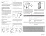
2. IMPORTANT! Before installing this control, check the factory default dip
switch settings. Refer to Figure 1. Be sure the dip switch positions of the
transmitter and receiver match, or the ceiling fan will not function. Select
different combinations of dip switches to prevent mis-operation due to
other remote control fans.
3. Determine your ceiling fan mounting type (Figure 2). Most installa-
tions will be one of these four types: Canopy Hanger, Hunter Hands-Free
TM
Canopy, Low Profi le Styles I and II, or Bracket Hanger.
4. Install the ceiling fan according to its instructions, up to the point of
making the electrical connections. Connect receiver to ceiling fan accord-
ing to the mounting type as instructed in Figure 2.
5. If the fan is already installed, turn the power OFF at the main electrical
panel. Reverse the installation procedure according to the fan instructions,
to the point of disconnecting the fan wiring. Connect the receiver to the
ceiling fan according to the mounting type as instructed in Figure 2.
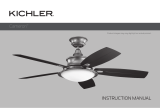
6. Use the 2 large wire nuts supplied to connect the receiver and house
wiring, then use the 3 small wire nuts supplied to connect the receiver and
ceiling fan wiring. Refer to the Wiring Diagram in Figure 3.
7. Be sure the antenna is positioned securely, so it can not interfere with
the ceiling fan motor. Refer to Figure 2. Do not modify or damage the
antenna wire, as control performance may be reduced. After securing the
receiver, antenna, and wiring, fi nish hanging the ceiling fan according to
its instructions.
Fan Installation Types:
NOTE: Some fans may have considerable excess lead wire. For easier
canopy installation, cut the excess wire leaving a minimum of 6 inches
remaining. Restrip the fan lead wires 1/2 inch. Place remaining excess wire
into the ceiling electrical box as needed.
Canopy Hanger (Fig. 2-A): Place receiver in canopy. Connect wiring as
shown in Figure 3. Extend antenna through one of the ceiling plate open-
ings (approximately 3–6˝).
Hunter Hands-Free™ Canopy (Fig. 2-B): Connect wiring as shown in
Figure 3. Place receiver inside mounting bracket. Extend antenna above
the ceiling mounting bracket (approximately 3–6˝).
Low Profi le Style I (Fig. 2-C): Secure receiver to the fan plate above the
motor with UL listed cable ties (not included). Connect wiring as shown
in Figure 3. Extend antenna through one of the ceiling plate openings
(approximately 3–6˝).
Low Profi le Style II (Fig. 2-D): Secure receiver to the ceiling mounting
bracket with UL listed cable ties (not included). Connect wiring as shown
in Figure 3. Extend antenna above the ceiling mounting bracket (approxi-
mately 3–6˝).
Bracket Hanger (Fig. 2-E): Starting with the antenna wire, slide receiver
inside mounting bracket. If a ground wire mounting screw prevents the
receiver from sliding into the bracket, move ground wire and screw to an
unused hole at the top of the bracket or secure with a canopy mount-
ing screw. The bracket must remain properly grounded. Connect wiring
as shown in Figure 3. Extend antenna above the receiver (approximately
5–8˝).
Cable Tie Routing for Low Profi le Fans (Figs. 2-C, 2-D): Insert cable tie
through openings as shown. DO NOT insert the cable
tie through the inside of the receiver. The cable tie
can be placed across the length or width of the
receiver to best match your fan installation type.
Fig. 2-A Fig. 2-B
Figure 2
Ceiling
Plate
Receiver
Canopy
Antenna
Ceiling
Plate
Receiver
Canopy
Antenna
Ceiling
Bracket
Receiver
Receiver
Placement
On Motor
Fan
Motor
Motor
Mounting
Plate
Antenna
Ceiling
Bracket
Receiver
Fan Body
Antenna
Antenna
Receiver
Canopy
Br ac ket
Canopy Hands-Free
TM
Canopy Low Profile I Low Profile II Bracket Hanger
Fig. 2-C Fig. 2-D
Fig. 2-E
TROUBLESHOOTING
HUNTER FAN COMPANY CONTROL LIMITED WARRANTY
The Hunter Fan Company makes the following limited warranty to the original purchaser of the Control (“Control”): Your Control is warranted to be free
from defects in material and workmanship for a period of one year from the date of sale. If the Control malfunctions or fails within the warranty period
due to a defect in material or workmanship we will replace it free of charge. IF THE ORIGINAL PURCHASER CEASES TO OWN THE CONTROL, THIS WAR-
RANTY AND ANY IMPLIED WARRANTY, INCLUDING BUT NOT LIMITED TO ANY IMPLIED WARRANTY OF MERCHANTABILITY OR FITNESS FOR A PARTICULAR
PURPOSE, ARE VOIDED. THIS WARRANTY IS IN LIEU OF ALL OTHER EXPRESS WARRANTIES. THE DURATION OF ANY IMPLIED WARRANTY, INCLUDING, BUT
NOT LIMITED TO, ANY IMPLIED WARRANTY OF MERCHANTABILITY OR FITNESS FOR A PARTICULAR PURPOSE, IN RESPECT TO ANY CONTROL, IS EXPRESSLY
LIMITED TO THE PERIOD OF THE EXPRESS WARRANTY SET FORTH ABOVE FOR SUCH CONTROL. This warranty excludes malfunctions or failures which were
caused by repairs by persons not authorized by us, mishandling, improper installation, modifi cations, or damage to the Control while in your possession,
or unreasonable use. This warranty does not apply to batteries or to deterioration or damage to the product caused by the use of faulty batteries. To
obtain a replacement, return your Control postage prepaid along with proof of purchase to Hunter Fan Company Service Department at 2500 Frisco Av-
enue, Memphis, Tennessee 38114. IN NO EVENT SHALL HUNTER FAN COMPANY BE LIABLE FOR CONSEQUENTIAL OR INCIDENTAL DAMAGES. SOME STATES
DO NOT ALLOW LIMITATIONS ON HOW LONG AN IMPLIED WARRANTY LASTS OR THE EXCLUSION OR LIMITATIONS OF INCIDENTAL OR CONSEQUENTIAL
DAMAGES SO THE ABOVE LIMITATIONS OR EXCLUSIONS MAY NOT APPLY TO YOU. THIS WARRANTY GIVES YOU SPECIFIC LEGAL RIGHTS AND YOU MAY ALSO
HAVE OTHER RIGHTS WHICH VARY FROM STATE TO STATE.
Symptom Possible Causes Solution
1. No functions operate.
2. Operates only at close range.
3. Inconsistent operation.
Main Power not restored. Replace fuse. Turn ON circuit breaker. Turn ON wall switch.
Signal blocked from reaching
receiver.
Extend antenna into ceiling box, or move it for better
reception.
Signal partially blocked from
reaching receiver.
Change dip switch settings to a different code in both
Transmitter and Receiver.
Fan pull chain not set to ON.
Light pull chain not set to ON.
Receiver wiring incorrect.
Transmitter and receiver dip
switches do not match.
Battery too weak.
Set fan pull chain to the desired speed.
Set light kit to ON.
Verify wiring connections.
Set transmitter and receiver to same dip switch setting.
Replace with new, 12 Volt alkaline battery. Refer to Figure 1.
Battery too weak.
Replace with new, 12 Volt alkaline battery. Refer to Figure 1.
RF interference.
Continuing RF interference.
Extend antenna into ceiling box, or move it for better
reception.
Turn OFF wall switch for 5 seconds, then turn back ON.
42715-01 01/03/2007
Printed in China
ON DIP
1
2
3
4
Receiver Back
Transmitter Back
Dip Switch
Dip Switch
ON DIP
1
2
3
4
12 VOLT
Figure 1
Light Kit Control
Fan Control
Figure 4
AC
Power
In
Light
Kit
Red
Black
White
Fan
White/Neutral
Black/Hot
Common
Antenna
Figure 3 Wiring Diagram
1. Light Operation:
• Press and quickly release the ON or OFF button on the remote control to
turn the light OFF or ON. (Light will come ON at maximum brightness.)
2. Fan Operation:
• Press and quickly release the ON or OFF button on the remote control to
turn the fan OFF or ON.
• To change the fan speed, slowly pull the fan pull-chain switch to select
the desired speed.

Control ON/OFF de Ventilador y Luz Hunter
Modelo 27157
Capacidad: Ventilador 120 VCA, 60 Hz,1.0 A Peso del receptor: 6 oz.
Lámpara incandescente de 300 Vatios
Lea Y Guarde Estas Instrucciones
Precaución: ¡Riesgo de choque eléctrico!
Todo cableado debe realizarse de acuerdo con los códigos
eléctricos locales y nacionales. Si no está familiarizado
con las normas de cableado, debe emplear un electricista
califi cado.
Para evitar el recalentamiento y el posible daño a
otros equipos, no instale la unidad para controlar un
receptáculo, un artefacto de iluminación fl uorescente,
un aparato operado por motor o alimentado por
transformador. Úselo sólo para controlar un ventilador de
techo con hojas de paleta y un artefacto de iluminación
incandescente o halógena.
Notas:
1. Este dispositivo cumple con la parte 15 de las reglas FCC. La operación
está sujeta a las siguientes dos condiciones: (1) este dispositivo no puede
causar una interferencia perjudicial, y (2) este dispositivo debe tolerar cu-
alquier interferencia recibida, incluyendo interferencias que puedan causar
una operación no deseada.
2. Este equipo se ha probado y cumple con los límites para un dispositivo
digital clase B, de acuerdo con la Parte 15 de las reglas FCC. Estos límites
están diseñados para proporcionar una protección razonable contra la
interferencia perjudicial en una instalación residencial. Este equipo genera,
usa y puede radiar energía de radio frecuencia, y si no se instala y usa de
acuerdo con las instrucciones, puede causar interferencia perjudicial a la
comunicación por radio. Sin embargo, no hay garantía de que no pueda
producirse interferencia en una instalación en particular. Si este equipo
causa alguna interferencia perjudicial a la recepción de radio o televisión,
lo que puede determinarse apagando y encendiendo el equipo, el usuario
debe tratar de corregir la interferencia aplicando una o más de las medi-
das siguientes:
• Reoriente o reubique la antena receptora.
• Aumente la separación entre el equipo y el receptor.
• Conecte el equipo en una salida de un circuito diferente del circuito en el
que está conectado el receptor.
• Consulte con su representante de ventas o con un técnico experimentado
de radio/TV.
3. Sólo para uso con ventiladores de techo con inversión de rotación, de
1.0 amperio o menos, y con conjuntos de lámparas incandescentes de 300
vatios o menos.
4. No debe usarse con motores de polo sombreado. No se recomienda su
uso con el modelo Hunter Original®. Para los ventiladores de la serie Hunt-
er Original®, use los controles Hunter modelos 22691, 27187, o 27189.
5. Este producto está diseñado para ser utilizado con un solo interruptor.
Si desea utilizar más de un interruptor para controlar la lámpara, consulte
a un electricista califi cado.
Cualquiera cambio o modifi cación a este equipo no aprobado expresa-
mente por Hunter Fan Company anulará la autorización del usuario para
operar el equipo.
Antes De Instalar El Control:
1. Use el interruptor tirador de cadena para establecer la velocidad del
ventilador a la posición ALTA antes de la instalación.
2. Fije el conjunto de luz del ventilador de techo en la posición ON antes
de la instalación. El nivel de iluminación sólo debe cambiarse usando el
control universal.
Instalación Del Receptor:
1. Desconecte la alimentación de energía al ventilador de techo y al
conjunto de luces en el panel eléctrico principal. Retire el fusible o mueva
el interruptor automático a la posición de apagado.
panel. Remove fuse or move circuit breaker to the OFF position.
2. ¡IMPORTANTE! Antes de instalar este control, verifi que los ajustes del
conmutador DIP predeterminados en fábrica. Vea la Figura 1. Asegúrese
que las posiciones del conmutador DIP del transmisor y del receptor
coincidan, o el ventilador de techo no funcionará. Seleccione diferentes
combinaciones de los conmutadores DIP para evitar la operación incor-
recta debido a controles remotos de otros ventiladores.
3. Determine el tipo de montaje de su ventilador de techo (Figura 2). La
mayoría de instalaciones será uno de estos cuatro tipos: Suspensión de
campana, Campana Hunter Hands-Free
TM
, Perfi l bajo Estilos I y II, o Suspen-
sión de soporte.
4. Instale el ventilador de techo de acuerdo con sus instrucciones, hasta la
realización de las conexiones eléctricas. Conecte el receptor al ventilador
de techo de acuerdo con el tipo de montaje, como se indica en la Figura 2.
5. Si el ventilador ya está instalado, apague la alimentación en el panel
eléctrico principal. Invierta el procedimiento de instalación de acuerdo con
las instrucciones del ventilador, hasta el punto de desconectar el cableado
del ventilador. Conecte el receptor al ventilador de techo de acuerdo con
el tipo de montaje, como se indica en la Figura 2.
6. Use los 2 empalmes plásticos grandes suministrados para conectar al re-
ceptor con el cableado ya existente, y luego los 3 pequeños para conectar
el receptor y el ventilador de techo. Consulte el Diagrama de cableado en
la Figura 3.
7. Asegúrese que la antena esté ubicada en forma segura para que no
pueda interferir con el motor del ventilador de techo. Consulte la Figura 2.
No modifi que ni dañe el alambre de la antena, ya que podría perjudicar el
funcionamiento del control. Después de asegurar el receptor, la antena y el
cableado, termine de suspender el ventilador de techo de acuerdo con las
instrucciones.
Tipos De Instalación De Ventilador:
NOTA: Algunos ventiladores pueden tener un considerable exceso de
conductor. Para una instalación más fácil de la campana, corte el alambre
en exceso dejando un mínimo de 6” (15 cm.) Pele nuevamente los extre-
mos de los alambres del ventilador 1/2”. Coloque el alambre de exceso
restante en la caja eléctrica de techo según sea necesario.
Suspensión De Campana (Fig. 2-A): Coloque el receptor en la campana.
Conecte los alambres como se muestra en la Figura 3. Extienda la antena
a través de una de las aberturas de la placa de techo (aproximadamente
entre 3” y 6”).
Campana Hunter Hands-Free™ (Fig. 2-B): Conecte los alambres como
se muestra en la Figura 3. Coloque el receptor dentro de un soporte de
montaje. Extienda la antena por encima del soporte de montaje de techo
(aproximadamente entre 3” y 6”).
Perfi l Bajo Estilo I (Fig. 2-C): Asegure el receptor a la placa del ventilador
sobre el motor con sujetacables aprobados por UL (no incluidos). Conecte
los alambres como se muestra en la Figura 3. Extienda la antena a través
de una de las aberturas de la placa de techo (aproximadamente entre 3”
y 6”).
Perfi l Bajo Estilo II (Fig. 2-D): Asegure el receptor al soporte de montaje del
techo con sujetacables aprobados por UL (no incluidos). Conecte los alambres
como se muestra en la Figura 3. Extienda la antena por encima del soporte de
montaje de techo (aproximadamente entre 3” y 6”).
Suspensión De Soporte (Fig. 2-E) : Comenzando con el alambre de la antena,
deslice el receptor dentro del soporte de montaje. Si el tornillo de montaje de
un alambre de tierra evita que el receptor se deslice en el soporte, mueva el
alambre de tierra y atorníllelo en un agujero no utilizado en la parte superior
del soporte o asegúrelo con un tornillo de montaje de campana. El soporte
debe permanecer puesto a tierra adecuadamente. Conecte los alambres como
se muestra en la Figura 3. Extienda la antena encima del receptor (aproxima-
damente entre 5” y 8”).
Colocación De Sujetacables Para Ventiladores De Perfi l Bajo (Fig. 2-C, 2-
D): Introduzca el sujetacables a través de las aberturas, tal como se muestra.
NO introduzca el sujetacables a través del
interior del receptor. El sujetacables puede colocarse
longitudinal o transversalmente al receptor para
adaptarse mejor al tipo de instalación de su
ventilador.
42715-02 01/03/2007
Impreso en China
Entrada
de
alimen-
tacion
CA
Conjunto
de Luz
Rojo
Negro
Blanco
Ventilador
Blanco/ Neutro
Negro/
Con tension
Comun
Antena
Figura 3 Diagrama de Cableado
LOCALIZACIÓN DE FALLAS
GARANTÍA LIMITADA DEL CONTROL DE HUNTER FAN COMPANY
Hunter Fan Company establece la siguiente garantía limitada al comprador original del Control (“Control”): Garantizamos que su Control no tendrá
defectos en materiales ni mano de obra por un año a partir de la fecha de compra. Si el Control presenta un funcionamiento defectuoso o una avería
dentro del período de garantía debido a un defecto en el material o la mano de obra, lo reemplazaremos en forma gratuita. SI EL COMPRADOR ORIGINAL
DEJA DE POSEER EL CONTROL, ESTA GARANTÍA Y CUALQUIER GARANTÍA IMPLÍCITA, INCLUYENDO, PERO SIN LIMITARSE A TODA GARANTÍA IMPLÍCITA
DE COMERCIABILIDAD O IDONEIDAD PARA UN PROPÓSITO PARTICULAR, QUEDA ANULADA. ESTA GARANTÍA SUSTITUYE A TODAS LAS OTRAS GARANTÍAS
EXPRESAS. LA DURACIÓN DE TODA GARANTÍA IMPLÍCITA, INCLUYENDO PERO SIN LIMITARSE A CUALQUIER GARANTÍA IMPLÍCITA DE COMERCIABILIDAD O
IDONEIDAD PARA UN PROPÓSITO PARTICULAR, RELACIONADA CON CUALQUIER CONTROL, ESTÁ EXPRESAMENTE LIMITADA AL PERÍODO DE LA GARANTÍA
EXPRESA ESTABLECIDA ANTERIORMENTE PARA DICHO CONTROL. Esta garantía excluye funcionamientos defectuosos o fallas causados por reparaciones
realizadas por personas no autorizadas por nosotros, mal uso, instalación incorrecta, modifi caciones, o daños al Control mientras esté en su posesión, o
por un empleo no razonable. Esta garantía no se aplica a las baterías ni al deterioro o daño al producto causado por el uso de baterías defectuosas. Para
obtener un reemplazo, devuelva su Control con el franqueo prepagado junto con una prueba de su compra al Departamento de servicio de Hunter Fan
Company, en 2500 Frisco Avenue, Memphis, Tennessee 38114. EN NINGÚN CASO HUNTER FAN COMPANY SERÁ RESPONSABLE DE DAÑOS PERJUDICIALES
O ACCESORIOS. ALGUNOS ESTADOS NO PERMITEN LIMITACIONES SOBRE LA DURACIÓN DE UNA GARANTÍA IMPLÍCITA O LA EXCLUSIÓN O LIMITACIÓN
DE DAÑOS ACCESORIOS O PERJUDICIALES, ASÍ QUE LAS LIMITACIONES O EXCLUSIONES ANTES MENCIONADAS PUEDEN NO APLICARSE A USTED. ESTA
GARANTÍA LE DA DERECHOS LEGALES ESPECÍFICOS, PERO USTED TAMBIÉN PUEDE TENER OTROS DERECHOS QUE VARÍAN DE ESTADO A ESTADO.
Síntoma Causas Posibles Solución
1. No opera ninguna función.
2. Opera sólo en un rango restringido.
3. Operación irregular.
La alimentación principal no se ha
restaurado.
Reemplace el fusible. Encienda el interruptor automático.
Encienda el interruptor de pared.
La señal no puede alcanzar al
receptor.
Extienda la antena en la caja de techo, o muévala para
obtener una mejor recepción.
La señal sólo alcanza parcialmente
al receptor.
Cambie los ajustes a un código diferente en el transmisor y
en el receptor.
La cadena del ventilador no está
fi jada en Alta.
El tirador de la cadena de luz no
está colocado en ON (encendido).
Cableado de receptor incorrecto.
Los ajustes del transmisor y el
receptor no coinciden.
Batería demasiado débil.
Coloque el interruptor de cadena del ventilador en la velocidad
deseada.
Fije el conjunto de luces en ON.
Verifi que las conexiones del cableado.
Fije el transmisor y el receptor al mismo ajuste.
Reemplace con una batería alcalina nueva de 12 voltios. Consulte la
Figura 1.
Batería demasiado débil.
Reemplace con una batería alcalina nueva de 12 voltios.
Consulte la Figura 1.
Interferencia de RF.
Interferencia continua de RF.
Extienda la antena en la caja de techo, o muévala para
obtener una mejor recepción.
Apague el interruptor de pared por 5 segundos y luego enciéndalo
otra vez.
Fig. 2-A Fig. 2-B
Figura 2
Placa de techo
Receptor
Campana
Antena
Placa de techo
Receptor
Campana
Antena
Soporte de techo
Receptor
Colocacion del
receptor
en el motor
Motor
del
ventilador
Placa de
montaje
del motor
Antena
Soporte de techo
Receptor
Motor del
ventilador
Antena
Antena
Receptor
Campana
Soporte
Suspensión De Campana Campana Hunter
Hands-Free
TM
Perfil Bajo Estilo I
Perfil Bajo Estilo II
Suspensión De Soporte
Fig. 2-C Fig. 2-D
Fig. 2-E
1. Operación de la luz:
• Presione y libere rápidamente el botón de luz en el control de pared para
apagar o encender la luz. (La luz se encenderá con el máximo brillo)
2. Operación Del Ventilador:
• Presione y libere rápidamente el botón de ON o OFF en el control de
pared para apagar o encender la luz.
• El ventilador empezará en ALTA velocidad. Para cambiar la velocidad del
ventilador, tire suavemente del interruptor de cadena del ventilador para
seleccionar la velocidad deseada.
ON DIP
1
2
3
4
Portacontrol Remoto
Parte Posterior
del Transmisor
Conmutador DIP
Conmutador DIP
ON DIP
1
2
3
4
12 VOL T
Figura 1
Control de kit de luz
Control de Ventalator
Figura 4
/