Page is loading ...

©2021 Hunter Fan Co.
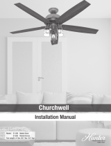
Model: 23845 White
23847 Chestnut Brown
23838 Black
23863 Black
51123 Matte Silver
Fan weight ±2 lbs: 43.2 lbs (19.6 kg)
PG3977 r040521
Historic 4 Blade Conguration
Classic 5 Blade Conguration
Installation Manual
Original
OR
(Page 9)
(Page 10)

1
Ladder
11/64” Drill BitDrill
#1
Screwdriver
#2
Screwdriver
Socket Wrench
Pliers
Wire Strippers
OPTIONAL
Congratulations on purchasing your new Hunter
®
ceiling fan!
Here are the tools you’ll need to complete your installation:
The ceiling fan you purchased will provide comfort and performance in your home or ofce for many years. This
instruction manual contains complete instructions for installing and operating your fan. We are proud of our work and
appreciate the opportunity to supply you with the best ceiling fan available anywhere in the world.
We are here to help!
This Instruction Manual is designed to make installation as simple as possible. While working through this Instruction
Manual, keep your smartphone or tablet nearby. We have added video links to help you through the more technical
sections. If you are unfamiliar or uncomfortable with wiring, contact a qualied electrician. We also provide telephone
support at 1.888.830.1326 or visit us at HunterFan.com.
WARNING
This product conforms to UL Standard 507
and is certied to STD C22.2 No.113..
READ and SAVE These Instructions
Warning
w.1 - To reduce the risk of re, electrical shock, or personal injury, mount fan directly from building structure and/or an outlet box marked acceptable for fan support of 70 lbs (31.8 kg) and use the
mounting screws provided with the outlet box.
w.2 - To avoid possible electrical shock, before installing or servicing your fan, disconnect the power by turning off the circuit breakers to the outlet box and associated wall switch location. If you
cannot lock the circuit breakers in the off position, securely fasten a prominent warning device, such as a tag, to the service panel.
w.3 – To reduce the risk of electric shock, this fan must be installed with an isolating wall control/switch.
w.4 - To reduce the risk of personal injury, do not bend the blade brackets when installing the blade brackets, balancing the blades, or cleaning the fan. Do not insert foreign objects in between
rotating fan blades.
Caution
c.1 - All wiring must be in accordance with national and local electrical codes ANSI/NFPA 70. If you are unfamiliar with wiring, use a qualied electrician.
c.2 - Use only Hunter replacement parts.
c.3 - To reduce the risk of personal injury, do not bend the blade attachment system when installing, balancing, or cleaning the fan. Never insert foreign objects between rotating fan blades.
c.4 - To reduce the risk of re, electrical shock, or motor damage, do not use a solid-state speed control with this fan. Use only Hunter speed controls.
c.5 - Wash your hands after your fan installation is complete.
c.6 - Use only with light kits marked suitable for damp locations.
If mounting to a support structure, you will also need these tools.
© 2021 Hunter Fan Company
7130 Goodlett Farms Pkwy, Suite 400
Memphis TN 38016

2
1886
1886
Do not discard the hardware bags or mix parts from
different bags. Make note of the symbol printed
on each hardware bag. The symbols can be used to
identify the appropriate hardware for each step.
For installing the blades
For installing the hanger bracket and wiring the fan
Hunter Pro Tip:
Find a part that is missing or damaged?
Don’t take it back to the store. Let us make it right. Visit us at HunterFan.com or call us at 1.888.830.1326.
Spare Parts
Balancing Kit
Oil Tube
Pull Chain Extension
Light Kit Adapter
For your convenience,
you may receive extra fasteners.
M3872-01 r040521
We recommend that you pull everything out of the box and lay it out. We have grouped
the drawn components below with the hardware you’ll need for those parts. The screws
below are drawn to scale to make it easier to identify what piece of hardware is needed
to install each component.
Here is what comes in your box:
If you are installing more than one fan, keep the blades
and blade irons in sets as they were shipped.
Installing Multiple Fans?
Canopy Assembly
Hanger Pipe
Motor
U-Bracket
Mounting
Bracket
Rubber Bushing
and Pin
Blade
Wire Nut
x2
x3
x5
x5
x15
x15
x10
3.5” Lag Screw
Blade Iron
Grommet
Blade Screw Blade Arm Screw

3
1886
1886
Choosing the Right Installation Location
Checking the Ceiling Angle:
Angled Mounting
If you have an angled or vaulted ceiling:
1. You will need a longer downrod. (sold separately at HunterFan.com)
2. If your ceiling angle is greater than 34°, you will also need an Angled
Mounting Kit. (Sold separately at HunterFan.com)
Check the room dimensions: Check the outlet box:
You must be able to
secure the fan to building
structure or fan-rated
outlet box.
30 inches
from blade tip to
nearest wall or
obstruction
7 feet
from bottom edge of
blade to the oor
Support Structure
Ceiling
Outlet Box
(required)
Angled Mounting
If you have a at ceiling:
Hang your fan by a standard downrod. Some fans come with
a shorter downrod for a Low Prole installation.
Support Structure
Ceiling Outlet
Box (required)
Standard Mounting
A little more information on Angled Mounting:
For optimum performance and appearance, a longer downrod should be used
with your Hunter ceiling fan when installing on high or angled ceiling. If your
ceiling is angled greater than 34° you will also need an Angled Mounting
Kit. Longer downrods and the Angled Mounting Kit are sold separately at
HunterFan.com.
Determining if you need an Angled Mounting Kit:
Fold on the dotted line. Place against edge againts the
wall. Slide towards the ceiling.
If the guide touches the wall but not the ceiling, you
need an angled mounting kit.
Hunter Pro Tip:
CEILING
WALL
34°
Installing the Ceiling Hardware
Hanging the Fan

4
1886
1886
Ceiling Bracket Downrod Hanging Fan Wiring Canopy Blades Operation Troubleshooting
Check the outlet box:
Installing the Ceiling Hardware
Hanging the Fan
Drill two (2) 11/64” diameter
holes 2-9/16” apart through the
back of the outlet box into the
cross brace 2” deep. These holes
are for the U-bracket bolts. Install
rubber bushing and pin into the
U-bracket. Use a 11 mm wrench
to install the (2) 3 1/2” lag bolts,
found in the hardware bag, to
secure the U-bracket to the joist
OFF
Turn Power
Installed View
Exploded View
8”
3/8”
C
U
T
&
S
T
R
I
P
(not to scale)
Excess wiring can be cut, but leave at
least 8” extending from the top of the
hanger pipe. NOTE: Some of the pipe
threads may still be visible
Feed the wires from the top of the
fan motor through the hanger pipe
Loosen the motor housing set
screw (do not completely remove
from the fan) in the neck of the fan
motor housing.
Screw the pipe into the fan until
tight (at least 4-1/2 turns)
1 2 3 4
STEP
STEP
STEP
STEP
Remove any existing bracket prior to installation. Only use the provided Hunter
ceiling bracket that came in your fan’s box.
WARNING
To avoid possible electrical shock, before
installing your fan, disconnect the power by
turning off the circuit breakers to the outlet
box associated with the wall switch location.
x2
3-1/2” Lag Bolt
IMPORTANT
DO NOT USE LUBRICANT ON SCREWS
IMPORTANT
TO SECURELY HANG THE FAN, CAREFULLY FOLLOW THE STEPS ON PAGES 7 AND 8. BE SURE TO TIGHTEN THE HANGER PIPE INTO
THE FAN AND THE HANGER BRACKET ONTO THE PIPE. TIGHTEN THE 2 SET SCREWS, AS DESCRIBED IN STEP 7, TO PREVENT THE
FAN FROM FALLING. YOUR FAN MAY WEIGH UP TO 50 LBS. ALL OF THE FOLLOWING STEPS MUST BE FOLLOWED IN ORDER TO
ENSURE A SECURE MOUNTING.
Cross Brace
Outlet Box
Rubber Bushing
and Pin
Ceiling
U-Bracket
Lag Bolt
Motor Housing
Motor Housing
Set Screw
Wires
Hanger Pipe

5
1886
1886
Ceiling Bracket Downrod Hanging Fan Wiring Canopy Blades Operation Troubleshooting
Hanging the Fan Wiring the Fan
Back out the set screw on the hanger bracket. Feed the wires through the
hanger bracket assembly and screw the hanger bracket onto the hanger
pipe until tight (at least 3 turns). Use pliers to tighten both the hanger
bracket assembly and the hanger pipe together.
Tighten the set screw in the motor housing and the hanger bracket assembly
NOTE: Some of the pipe threads may still be visible.
Be sure that the pin is centered in the rubber bushing.
Lift the fan by the motor housing. Hook the hanger bracket assembly onto
the rubber bushing and pin. Ensure both ends of the pin are outside the
hanger bracket assembly
5
7
6
8
STEPSTEP
STEPSTEP
IMPORTANT
TO SECURELY HANG THE FAN, CAREFULLY FOLLOW THE STEPS ON PAGES 7 AND 8. BE SURE TO TIGHTEN THE HANGER PIPE INTO
THE FAN AND THE HANGER BRACKET ONTO THE PIPE. TIGHTEN THE 2 SET SCREWS, AS DESCRIBED IN STEP 7, TO PREVENT THE
FAN FROM FALLING. YOUR FAN MAY WEIGH UP TO 50 LBS. ALL OF THE FOLLOWING STEPS MUST BE FOLLOWED IN ORDER TO
ENSURE A SECURE MOUNTING.
WARNING
FAN FALL HAZARD
To prevent SERIOUS INJURY or DEATH:
• ALWAYS tighten setscrew with pliers.
• DO NOT
hand tighten setscrew.
WARNING
Never lift the motor by the wires.
Let motor rest in the carton liner
for protection.
Hanger Bracket
Hanger Bracket
Set Screw
Rubber
Bushing & Pin
Hanger Bracket
Assembly
Motor Housing
Set Screw
Hanger Pipe
Pin
Rubber
Bushing

6
1886
1886
Ceiling Bracket Downrod Hanging Fan Wiring Canopy Blades Operation Troubleshooting
Wiring the Fan
We know wiring is hard. Let’s make it easier.
You are going to need these:
4 Wire Nuts (these are in the bag)
Follow these steps to get your fan wired quickly and safely. Follow the route below that best matches
your wall switch setup. If you are unfamiliar with wiring or uncomfortable doing it yourself, please
in accordance with national and local electrical codes.
Have a single switch?
Follow these steps:
Have dual switches?
Follow these steps:
Hunter Pro Tip:
Here is how to connect the wires:
Push the bare metal ends of the wires together and slide a wire nut over
them. Then, twist the wire nut clockwise until tight. Give it a gentle
pull to make sure none of the wires are loose.
Connect the white
(grounded) wire
from the ceiling
to the white wire
from the fan.
Connect the white
(grounded) wire
from the ceiling
to the white wire
from the fan.
Connect the second ungrounded
(light) wire from the ceiling to the
blue wire from the fan.
Connect the bare or green ground
wire (grounding) from the ceiling
to the side of the hanger bracket
assembly.
Connect the bare or green ground
wire (grounding) from the ceiling
to the side of the hanger bracket
assembly.
Connect the black
(ungrounded) wire from
the ceiling to the black
wire from the fan.
Blue
Black
White
White
Ungrounded
UngroundedUngrounded
Ungrounded
(light)
Grounded
Grounded
Grounding
x3
x3
Wire Nut
Wire Nut
Connect the black wire
(ungrounded) from the
ceiling to the black and the
blue wires from the fan.
Black
Blue
WARNING
All wiring must be in accordance with national
and local electrical codes ANSI/NFPA 70. If you
are unfamiliar with wiring or in doubt, consult
a qualied electrician.
WARNING
The ceiling fan must be grounded. If the
ground wire for the installation site is not
present, immediately STOP installation and
consult a qualied electrician.
Have extra wiring?
Turn the wires upward and push them carefully back through the
hanger bracket into the outlet box. Spread the wires apart, with the
grounded wires on one side of the outlet box and the ungrounded
wires on the other side of the outlet box. Make sure that the wires
are still attached to the wire nuts.
Hunter Pro Tip:
WARNING
NO BARE WIRES OR WIRE
STRANDS SHOULD BE VISIBLE
AFTER MAKING CONNECTIONS.
WARNING
To avoid possible electrical shock, before
installing your fan, disconnect the power by
turning off the circuit breakers to the outlet
box associated with the wall switch location.
Grounding

7
1886
1886
Ceiling Bracket Downrod Hanging Fan Wiring Canopy Blades Operation Troubleshooting
Installing the Canopy
Lubrication
IMPORTANT
IMPORTANT
Your canopy comes pre-assembled. Uninstall the canopy screws using a #1 Phillips-head screwdriver and separate the two halves of the
canopy before continuing to step 1.
DO NOT TURN FAN ON UNTIL LUBRICATION HAS BEEN ADDED. TO OPERATE THE FAN WITHOUT OIL OR WITH LOW OIL WILL VOID
YOUR WARRANTY.
Assemble canopy halves around pipe, and loosely
install the canopy assembly screws. Slide canopy up
close to ceiling.
Tighten the canopy assembly screws using
a #2 Phillips-head screwdriver.
Tighten the canopy set screw using a #1
Phillips-head screwdriver.
1 3 4
STEP
STEP
STEP
Remove cap if present. Cut the tip off the end of the tube.
Place the tube into the oil hole and gently squeeze the tube to empty the oil
into the fan’s reservoir.
NOTE: To avoid overowing during lling, add a third of the oil from the tube
at a time. Pause for 30 seconds between each third to allow the oil to settle
in the fan. Be sure to add all of the oil in the tube to the fan.
1 2
STEP
STEP
Your fan has been shipped without oil in the motor. A tube of high grade SAE 10 non-detergent oil is packaged in the hardware bag.
The bearings in your Hunter Original Ceiling Fan are submerged in oil, which lubricates all bearing surfaces as the fan operates. We recommend periodically checking the oil to
ensure the correct level is maintained. This unique lubrication system is one reason why your Hunter Original Ceiling Fan will last a lifetime.
Note:
Your Original Hunter’s Unique Lubricating System
Canopy
Set Screw
Oil Bottle
Oil Bottle
Oil Hole
Canopy
Assembly Screw
Canopy
Assembly Screw

8
1886
1886
x15
x15
Insert grommets found in the hardware bag into the
holes in the blades, then secure each blade to a blade arm
with screws found in the hardware bag.
Repeat x 4 x5
Choose 4 or 5 Blade Installation
bag
bag
Blade Screw
Grommet
Ceiling Bracket Downrod Hanging Fan Wiring Canopy Blades Operation Troubleshooting
Fan Blade Assembly
Choose How Many Fan Blades You Want
First lets construct the blades.
You have a piece of Hunter’s history in your
space. Choose how you want its story to unfold.
For 135 years, the four bladed installation
option has provided the historic look of the
Original. Install it with ve blades for a fresh
take that’s still familiar.
Grommet
Blade Screw
OR
OR

9
1886
1886
Repeat x 4
HISTORIC
Four Blade Conguration
Installing the Blades: HISTORIC 4 Blade Conguration
For four blades, use the inner row. For
each blade, insert one blade mounting
screw, found in the hardware bag,
through the blade iron, and attach
lightly to the fan. Insert the second blade
mounting screw, then securely tighten
both mounting screws
x8
bag
Blade
Mounting
Screw
4
Inner Row
for 4 Blades
Blade
Mounting
Screw
NOTICE
TO REDUCE THE RISK OF PERSONAL INJURY, DO NOT
BEND THE BLADE BRACKETS WH EN INSTALLING THE
BRACKETS, BALANCING THE BLADES, OR CLEANING
THE FAN. DO NOT INSERT FOREIGN OBJECTS IN
BETWEEN ROTATING FAN BLADES.
Ceiling Bracket Downrod Hanging Fan Wiring Canopy Blades Operation Troubleshooting

10
1886
1886
Repeat x 5
CLASSIC
Five Blade Conguration
Installing the Blades: CLASSIC 5 Blade Conguration
Blade
Mounting
Screw
Outer Row
for 5 Blades
For ve blades, use the outer row.For
each blade, insert one blade mounting
screw, found in the hardware bag,
through the blade iron, and attach
lightly to the fan. Insert the second blade
mounting screw, then securely tighten
both mounting screws
x10
bag
Blade
Mounting
Screw
5
NOTICE
TO REDUCE THE RISK OF PERSONAL INJURY, DO NOT
BEND THE BLADE BRACKETS WH EN INSTALLING THE
BRACKETS, BALANCING THE BLADES, OR CLEANING
THE FAN. DO NOT INSERT FOREIGN OBJECTS IN
BETWEEN ROTATING FAN BLADES.
Ceiling Bracket Downrod Hanging Fan Wiring Canopy Blades Operation Troubleshooting

11
1886
1886
Checking Oil
Ceiling fans work in two directions: downdraft
(counterclockwise rotation) and updraft (clockwise
rotation). To change the direction of air ow, turn the
fan off and let it come to a complete stop. Slide the
reversing switch to the opposite position. Restart the
fan. Move the directional lever down for down draft.
Move the directional lever up for up draft.
Attach the pull chain pendant to the fan pull chain.
The fan pull chain controls power to the fan. The pull
chain has four settings in sequence: High, Medium,
Low, and Off. Pull the chain slowly to change
settings. Release slowly to prevent the chain from
recoiling into the blades.
Fan Operation
Updraft (clockwise rotation)
creates a more indirect airow.
Updraft airow is great for moving
warm air downward.
Downdraft (counterclockwise
rotation) creates a direct breeze
and maximum cooling effect.
Check oil level immediately after lling the reservoir and every 1 to 5 years
thereafter. To check oil, bend an ordinary pipe cleaner into 1/2” long hook
and dip it into the oil reservoir.
If the oil touches the end of the pipe cleaner, the fan has ample oil. If it does
not touch, add SAE 10 non-detergent oil slowly until it touches the
pipe cleaner
1 2
STEP
STEP
Ceiling Bracket Downrod Hanging Fan Wiring Canopy Blades Operation Troubleshooting
Reverse
Switch
ON
Turn Power
Pipe
Cleaner
Pipe
Cleaner
1/2”
IMPORTANT
DO NOT TURN FAN ON UNTIL LUBRICATION HAS
BEEN ADDED. TO OPERATE THE FAN WITHOUT OIL
OR WITH LOW OIL WILL VOID YOUR WARRANTY.

12
1886
1886
Troubleshooting
Fan Doesn’t Work
• Make sure power switch is on.
• Pull the pull chain to make sure it is on.
• Push the motor reversing switch rmly left or right to ensure that it is engaged.
• Check the circuit breaker to ensure the power is turned on.
• Make sure the blades spin freely. Note: If the blades will not turn by hand, contact your nearest
service representative or dealer.
• Turn off power from the circuit breaker, then loosen the canopy and check all the connections
according to the wiring diagram.
Excessive Wobbling
• Tighten the blade assembly screws and blade iron screws until they are snug.
• Ensure the fan is secured properly to the hanger assembly.
• Use the provided balancing kit and instructions to balance the fan.
Noisy Operation
• Tighten the blade assembly screws and blade iron screws until they are snug.
• Check to see if any of the blades are cracked. If so, replace all the blades.
• Lower the canopy so it does not make contact with the ceiling.
• Check the oil level and add oil if required (see page 13 for details).
Fan Only Operates at Slow Speeds
• Contact your nearest service representative or dealer.
Cleaning the Fan
blades with a furniture polishing cloth. Occasionally, apply a light coat of furniture polish for added protection and beauty.
Hunter Pro Tip:
Hunter Fan Company grants this limited warranty to the original purchaser of this Hunter
ceiling fan. This document can be found at www.HunterFan.com.
Thank you for choosing Hunter!
How Can Warranty Service Be Obtained?
Proof of purchase is required when requesting warranty service. The original
purchaser must present a sales receipt or other document that establishes proof of purchase.
Hunter, at its sole discretion, may accept a gift receipt. To obtain service, contact Hunter Fan
Company online or by phone.
www.HunterFan.com/Support/Contact-Us/
1-888-830-1326
Please do not ship your fan or any fan parts to Hunter. Delivery will be refused.
What Does This Warranty Cover?
Motor — Limited Lifetime Warranty
If any part of your ceiling fan motor fails during your ownership of the fan due to a defect in
material or workmanship, as determined solely by Hunter, Hunter will provide you with a
replacement fan free of charge.* The foregoing limited warranty applies only to the motor itself
and does not apply to electronic controls – such as remote control transmitters, remote control
receivers, or capacitors – used in conjunction with the motor. Such electronic control items are
included in the one-year limited warranty below.
Other — One-Year Limited Warranty
Except as otherwise indicated throughout this warranty, if any part of your Hunter ceiling
fan fails at any time within one year of the date of purchase due to a defect in material or
workmanship, as determined solely by Hunter, Hunter will provide a replacement part free of
charge.*
* If no replacement product/part can be provided for your fan, we will provide a comparable or superior
replacement product/part at the sole discretion of Hunter.
What Does This Warranty NOT Cover?
Labor Excluded. This warranty does not cover any costs or fees associated with the labor
(including electrician’s fees) required to install, remove, or replace a fan or any fan parts.
There is no warranty for light bulbs (except where otherwise noted); remote control batteries;
fans purchased or installed outside the United States; fans owned by someone other than the
original purchaser; fans for which proof of purchase has not been established; fans purchased
from an unauthorized dealer; ordinary wear and tear; minor cosmetic blemishes; refurbished
fans; and fans that are damaged due to any of the following: improper installation, misuse,
abuse, improper care, failure to follow Hunter instructions, accidental damage caused by
the fan owner or related parties, modications to the fan, improper or incorrectly performed
maintenance or repair, improper voltage supply or power surge, use of improper parts or
accessories, failure to provide maintenance to the fan, or acts of God (e.g. ood).
ORIGINAL PURCHASER’S SOLE AND EXCLUSIVE REMEDY FOR A CLAIM OF ANY KIND WITH
RESPECT TO THIS PRODUCT SHALL BE THE REMEDIES SET FORTH HEREIN. HUNTER FAN
COMPANY IS NOT RESPONSIBLE FOR CONSEQUENTIAL OR INCIDENTAL DAMAGES, DUE TO
PRODUCT FAILURE, WHETHER ARISING OUT OF BREACH OF WARRANTY, BREACH OF CONTRACT,
OR OTHERWISE. Some States do not allow the exclusion or limitation of incidental or
consequential damages, so the above limitation or exclusion may not apply to you.
ANY IMPLIED WARRANTIES OF MERCHANTABILITY OR FITNESS FOR A PARTICULAR PURPOSE
APPLICABLE TO THIS PRODUCT ARE LIMITED IN DURATION TO THE PERIOD OF COVERAGE OF
THE APPLICABLE LIMITED WARRANTIES SET FORTH ABOVE. Some States do not allow limitations
on how long an implied warranty lasts, so the above limitation may not apply to you.
How Does State Law Affect Warranty Coverage?
This warranty gives you specic legal rights. You may also have other rights which vary from
state to state.
Limited Lifetime Warranty
Fan Operation
Ceiling Bracket Downrod Hanging Fan Wiring Canopy Blades Operation Troubleshooting
/