Page is loading ...

SK P25012EQ6-2IN

Assembling Your Telescope
Aligning the Finderscope
Balancing the Telescope
Operating the EQ6 Mount
Using the Hand Control
Using the Barlow Lens
Focusing
Polar Alignment
The Polarscope
Tracking Celestial Objects
Setting Circles
Choosing the appropriate eyepiece
Operating Your Telescope
Parts Diagram
Tripod Set up
Mount Assembly
Telescope Assembly
Finderscope Assembly
Eyepiece Assembly
Hand Control Instrallation
Proper Care for Your Telescope
Observing the Sky
Sky Conditions
Selecting an Observing Site
Choosing the Best Time to Observe
Chooling the Telescope
Adapting Your Eyes
Collimating a Newtonian reflector
Cleaning Your Telescope
3
6
3
4
4
4
5
5
5
6
6
7
7
8
8
8
9
11
12
13
14
14
14
14
14
15
16
14
15
B
efore you begin
C
aution!
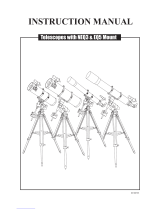
Read the entire instructions carefully before
beginning. Your telescope should be assembled
during daylight hours. Choose a large, open
area to work to allow room for all parts to be
unpacked.
T
echnical Support
Please contact your dealer for technical support.
NEVER USE YOUR TELESCOPE TO LOOK
DIRECTLY AT THE SUN. PERMANENT EYE
DAMAGE WILL RESULT. USE A PROPER SOLAR
FILTER FOR VIEWING THE SUN. WHEN
OBSERVING THE SUN, PLACE A DUST CAP
OVER YOUR FINDERSCOPE TO PROTECT IT
FROM EXPOSURE. NEVER USE AN EYEPIECE-
TYPE SOLAR FILTER AND NEVER USE YOUR
TELESCOPE TO PROJECT SUNLIGHT ONTO
ANOTHER SURFACE, THE INTERNAL HEAT
BUILD-UP WILL DAMAGE THE TELESCOPE
OPTICAL ELEMENTS.

Finderscope
Dust Cap/Mask
(Remove before viewing)
Focuser Knob
Focuser Tube
Eyepiece
Mounting Plate
Dual Axis Motor Drives
(not shown)
Dec Lock Lever
Dec Setting Circle
Counterweight Rod
Lock Knob
Counterweight
Thumbscrew
Counterweight
Counterweight Rod
Hand Control
Finderscope Bracket
Alignment Screw
Focus Locking Screw
Piggyback Bracket
Tube Rings
Pirmary Mirror Position
R.A. Lock Lever
Polarscope Holder
(not shown)
Latitude Scale
Azimuth Adjustment Knobs
Accessory Tray
Tripod Leg
Height Adjustment Clamp
Altitude Adjustment T-bolt
3

4
MOUNT ASSEMBLY
Fig. 1
ASSEMBLING THE TRIPOD LEGS (Fig.1)
1) Slowly loosen the height adjustment clamp and
gently pull out the lower section of each tripod
leg. Tighten the clamps to hold the legs in place.
2) Spread the tripod legs apart to stand the tripod upright.
3) Place a carpenter's level or bubble level on the top of
the tripod legs. Adjust the height of each tripod leg until
the tripod head is properly leveled. Note that the tripod
legs may not be at same length when the equatorial
mount is level.
ATTACHING THE ACCESSORY TRAY (Fig. 3)
1) Slide the accessory tray along the primary locking
shaft until it pushes against the tripod legs.
2) Secure with the washer and locking knob.
ATTACHING MOUNT TO TRIPOD LEGS (Fig. 2)
1) Align metal dowel on the tripod head with the gap between
the azimuth adjustment knobs underneath the mount.
2) Push the primary locking shaft up against the mount and
turn the knurled knob underneath to secure mount to tripod.
Fig. 3
Fig. 4
Fig. 5
TRIPOD SET UP
Fig. 2.
Note: Loosen the azimuth adjustment knobs if mount does not
fit into tripod head completely. Retighten knobs to secure.
INSTALLING THE COUNTER-
WEIGHTS (Fig. 4, 5)
1) Loosen the counterweight rod lock knob and gently
pull out the counterweight rod. Re-tighten the lock
knob to secure the counterweight rod in place.
2) Unscrew the threaded cap from the end of the
counterweight rod.
3) Locate the counterweights and slide them halfway
along the counterweight rod. Tighten the counterweight
thumb screws to secure.
5) Replace the cap on the end of the counterweight rod.
EQ-6
TELESCOPE ASSEMBLY
Fig. 6
Fig. 7
EQ-6
ATTACHING THE MOUNTING PLATE (Fig.6)
1) Position the mounting plate on the mounting bracket.
2) Secure by tightening the two locking screws.
ATTACHING THE TUBE RINGS (Fig.7)
1) Remove the telescope tube assembly from
its plastic packaging.
2) Remove the tube rings from the telescope by
releasing their thumb nuts and opening their hinges.
3) Using the bolts provided, fasten the tube rings to
the mount with the 10mm wench provided.

5
FINDERSCOPE ASSEMBLY
ATTACHING THE FINDERSCOPE
BRACKET (Fig. 9,10,11)
1) Locate the finderscope bracket. Carefully remove
the rubber-o-ring from the finderscope bracket.
2) Position the o-ring into the groove located
approximately half-way along the finderscope tube.
3) Locate the finderscope optical assembly.
4) Slide the finderscope bracket into the rectancular
slot and tighten the screw to hold the mount in place.
5) Position the finderscope into its bracket by sliding
it backwards until the rubber o-ring seats in the
finderscope mount.
Fig. 8
ATTACHING THE TELESCOPE MAIN TUBE TO THE
TUBE RINGS (Fig.8)
1) Remove the telescope tube from the paper covering.
2) Find the center of balance of the telescope tube.
Place this in between the two tube rings. Close the
hinges around the telescope and fasten securely by
tightening the thumb nuts.
TELESCOPE ASSEMBLY
Fig.9
Fig.10
Fig.11
POWERING THE
EQ6 MOTORS (Fig. 13)
1) Insert eight "D" cell batteries
into the battery case.
2) Plug the DC power cord
from battery case into the
DC 12V outlet on the side
of the mount.
CONNECTING THE
HAND CONTROL (Fig. 13)
1) The EQ6 hand control has a phone
type connector. Plug the phone jack
connector into the outlet on the
mount. Push the connector into
the outlet until it clicks into place.
HAND CONTROL INSTALLATION
Fig. 13
Fig. 12
P
o
w
e
r
D
C
1
2
V
EYEPIECE ASSEMBLY
INSERTING EYEPIECE (Fig. 12)
1) Unscrew the thumbscrews on the end of the focus
tube to remove the black plastic end-cap.
2) Re-tighten thumb screws to hold the eyepiece in place.

6
A
ligning the finderscope
Fig.a
Fig.a-1
These fixed magnification scopes mounted on the optical tube are
very useful accessories. When they are correctly aligned with the
telescope, objects can be quickly located and brought to the centre
of the field. Alignment is best done outdoors in daylight when it's
easier to locate objects. If it is necessary to refocus your
finderscope, sight on an object that is at least 500 yards (metres)
away. Loosen the locking ring by unscrewing it back towards the
bracket. The front lens holder can now be turned in and out to
focus. When focus is reached, lock it in position with the locking
ring (Fig.a).
Choose a distant object that is at least 500 yards away and point
the main telescope at the object. Adjust the telescope so that the
object is in the centre of the view in your eyepiece.
Check the finderscope to see if the object centred in the main
telescope view is centred on the crosshairs.
Adjust the two small screws to centre the finderscope crosshairs
on the object (Fig.a-1).
1)
2)
3)
B
alancing the telescope
Fig.b
A telescope should be balanced before each observing session. Balancing reduces stress on the telescope
mount and allows precise control of micro-adjustment. A balanced telescope is specially critical when doing
astrophotography.
The telescope should be balanced after all accessories (eyepiece, camera, etc.) have been attached. Before
balancing your telescope, make sure that your tripod is balanced and on a stable surface. For photography, point
the telescope in the direction you will be taking photos before performing the balancing steps.
R.A. Balancing
1) Slowly unlock the R.A. and Dec lock levers. Rotate the
telescope until both the optical tube and the counterweight
rod are horizontal to the ground, and the telescope tube
is to the side of the mount (Fig.b).
2) Tighten the Dec. lock lever.
3) Move the counterweights along the counterweight rod until
the telescope is balanced and remains stationary when released.
4) Tighten the counterweight thumbscrews to hold the
counterweights in their new position.
Dec. Balancing
All accessories should be attached to the telescope before balancing around the declination axis. The R.A.
balancing should be done befor proceeding with Dec. balancing.
1) Release the R.A. lock lever and rotate R.A. axis so that the counterweight rod is in horizontal position.
Tighten the R.A. lock lever.
2) Unlock the Dec. lock lever and rotate telescope tube until it is parallel to the ground.
3) Slowly release the telescope and determine which direction the telescope rotates. Loosen telescope tube
rings and slide telescope tube forward or backward in the rings to balance Dec. axis.
4) Once the telescope no longer rotates from its parallel starting position, re-tighten the tube rings and the Dec.
lock lever. Reset the altitude axis to your local latitude.

7
O
perating the EQ6 mount
Fig.c
Altitude
adjustment
Azimuth
adjustment
EQ-6
Dec. adjustment
R.A. adjustment
Latitude
scale
Dec. scale
R.A. scale
The EQ6 mount has controls for both conventional altitude
(up-down) and azimuthal (left-right) directions of motion. Use
the altitude adjustment T-bolts for altitude adjustments. These
allow fine-adjustment for setting the mount to your local
latitude. The azimuthal axis is changed by the two azimuth
adjustment knobs located near the tripod head. These allow
fine-adjustment of azimuth for polar aligning (Fig.c).
In addition, this mount has direction controls for polar
aligned astronomical observing. These directions use Right
Ascension (east/west) and Declination (north/south) axis.
There are two options to move the telescope in these
directions: For large and quick movement, loosen the R.A.
lock lever under the R.A. shaft or the Dec. lock lever near the
top of the mount (Fig.c-1). For fine adjustments, use the
motor drive hand control (see "Using the Hand Control").
There are three numerical scales on this mount. The lower
scale on the side of the mount is used for polar alignment of
the telescope to your local latitude. The R.A. (Right
Ascension) scale is measures hour angle and is adjustable
to your local meridian. The declination scale is located near
the top of the mount (Fig.c-2).
U
sing the hand control
Fig.d
Power/direction
switch
Rate switch
Dec control
buttons
R.A control
buttons
N
OFF
S
2X
8X
16X
Dec
Dec
R.A
R.AR.A
The N/Off/S switch acts as a power switch as well as
controlling the directions of the motors. The "N" position
allows R.A. motor to track for the Northern Hemisphere
observations and the "S" position is suitable for the Southern
Hemisphere (Fig.d). When the EQ6 Hand Control is turned
on and all buttons are depressed, the R.A. motor will rotate at
the proper speed to compensate for the earth's rotation. The
Dec. axis does not automatically rotate. When the mount is
correctly polar aligned, you only need to turn the R.A. slow-
motion to follow or track objects as they move through the
field. The Dec. control is not needed for tracking.
The four push buttons control the directions of the motors.
The up-down buttons control the declination motor while the
left-right buttons change the R.A. axis.
The rate switch allows changes to the speed rate of the
motors from high speed slew rate (16X) to slow micro-
adjustment (2X) and the speed in between (8X). When the
rate switch is set on "2X", pressing the right R.A. button will
rotate the telescope forward at twice the tracking speed or
approximately ½º per minute. The left R.A. button stops all
motion and allows stars to drift by at their normal rotation
rate of approx. ¼º per minute. The "8X" settings allows
forward at 8 times the tracking rate and the reverse button
moves the telescope backwards at 7 times the tracking rate.
The "16X" setting allows forward at 16 times the tracking rate
and the reverse button moves the telescope backwards at 15
times the tracking rate.
Fig.c-1
Fig.c-2

8
Fig.e
U
sing the optional Barlow lens
A Barlow is a negative lens which increases the magnifying
power of an eyepiece, while reducing the field of view. It
expands the cone of the focussed light before it reaches the
focal point, so that the telescope's focal length appears
longer to the eyepiece.
The Barlow is inserted between the focuser and the eyepiece
in a reflector (Fig.e). In addition to increasing magnification,
the benefits of using a Barlow lens include improved eye
relief, and reduced spherical aberration in the eyepiece. For
this reason, a Barlow plus a lens often outperform a single
lens producing the same magnification. However, its greatest
value may be that a Barlow can potentially double the
number of eyepiece in your collection.
F
ocusing
Fig.f
Slowly turn the focus knobs under the focuser, one way or the
other, until the image in the eyepiece is sharp (Fig.f). The image
usually has to be finely refocused over time, due to small
variations caused by temperature changes, flexures, etc. This
often happens with short focal ratio telescopes, particularly when
they haven't yet reached outside temperature. Refocusing is
almost always necessary when you change an eyepiece or add
or remove a Barlow lens.
Barlow
Eyepiece
In order for your telescope to track objects in the sky you have to align your mount. This means tilting the head
over so that it points to the North (or South) celestial pole. For people in the Northern Hemisphere this is rather
easy as the bright star Polaris is very near the North Celestial Pole. For casual observing, rough polar alignment is
adequate. Make sure your equatorial mount is level and the red dot finder is aligned with the telescope before
P
olar alignment
Fig.g
0
10
20
30
4
0
50
60
70
80
90
Setting the latitude
Remove the telescope tube and the counterweights from the mount.
Find the latitude and time zone of your current location. A road atlas
or GPS unit is useful for your local geographic coordinates. Now look
at the side of your mount head, there you will see a scale running
from 0-90 degrees (Fig.g). At the base of the head, just above the
legs, are two screws (latitude adjustment t-bots) opposite each other
under the hinge. All you have to do is loosen one side and tighten the
other until your latitude is shown by the indicator pointer (Fig.i).
Loosening the front T-bolt first will make the adjustments easier. Small
adjustments may be needed after re-attaching the telescope tube and
the counterweights.
Polaris, the "Pole Star" is less than one degree from the North
Celestial Pole (NCP). Because it is not exactly at the NCP, Polaris
appears to trace a small circle around it as the Earth rotates. Polaris
is offset from the NCP, toward Cassiopeia and away from the end of
the handle of the Big Dipper (Fig.g-1).

9
Alligning your telescope to Polaris
Unlock the DEC lock knob and rotate the telescope tube until
the pointer on the setting circle reads 90˚. Retighten the DEC
lock knob. Move the tripod so that the equatorial mount faces
north and the R.A. axis points roughly at Polaris. A hand
campass is useful for this step. Use the two azimuth
adjustment knobs on the mount base to make fine
adjustments in azimuth if needed (Fig.g-2). For more
accurate allignment, look through the finderscope and centre
the Polaris on the crosshairs.
Southern Hemisphere
In the Southern Hemisphere you must align the mount to the
SCP by locating its position with star patterns, without the
convenience of a nearby bright star. The closest star is the
faint 5.5-mag. Sigma Octanis which is about one degree
away. Two sets of pointers which help to locate the SCP are
alpha and beta Crucis (in the Southern Cross) and a pointer
running at a right angle to a line connecting alpha and beta
Centauri (Fig.g-3).
+
Polaris
Cassiopeia
Little Dipper
Big Dipper
NCP
T
he Polarscope
omega
Octanis
alpha
Centauri
beta
Centauri
alpha
Crucis
beta
Crucis
SCP +
The pole-finder telescope supplied with the EQ-6 Mount can
be used for accurate polar alignment. This method of polar
alignment is sufficient for virtually all visual use of the
telescope.
To use the Polarscope with the EQ-6 mount, the declination
axis must be rotated such that the hole in the shaft is in front
of the Polarscope. If possible, this procedure should be
carried out while the telescope and counterweights are on
the mount. This prevents the mount from becoming mis-
aligned when the load on the tripod is changed. Be sure that
the tripod is level. This will make it easier to use the Azimuth
and Altitude adjustments on the mount when trying to center
the stars in the polar scope. The tripod can be made level by
using a bubble level or carpenter's level. Remove the caps
from the upper and lower ends of the Right Ascension (R.A.)
axis (Fig.h). Looking through the polar scope, lines should be
seen super-imposed on the sky. If these lines are not visible,
shine a red flashlight down the upper end of the RA axis to
illuminate the top end of the pole finder.
Aligning the Polarscope
The optical axis of the polar scope is already aligned with the
rotation axis of the mount. The optical axis of the polar scope
can not be adjusted. This is set permanently at the factory.
The reticle in the polar scope must be centered on the optical
axis of the polar scope. If this is not the case, the polar
alignment will not be accurate.
Fig.h
Power
DC 12V
Fig.g-1
Fig.g-2
Fig.g-3

10
Locate Polaris and place it in the center of the Polarscope by
adjusting the Altitude and Azimuth of the mount. Place
Polaris directly under the cross in the center of the reticle
(Fig.h-1). Rotate the mount one half turn about the R.A. axis.
Polaris should remain under the cross in the center of the
reticle. If it does not, the reticle is not centered on the R.A.
axis of the mount.
To move the reticle, adjust the three small Allen screws
(Fig.h-2) on the polar scope. Make small adjustments by
moving only two of the screws at a time. Adjust the screws to
move Polaris
half
the distance back to the center of the
reticle. This is because Polaris started in the center of the
reticle. By rotating the mount 180 degrees, Polaris moved
exactly twice the distance between the center of the reticle
and the center of rotation. The center of rotation lies midway
between the center of the reticle and the new position of
Polaris. Do not turn any of the set screws more than one
quarter turn at a time or the reticle will disengage from the
set screws. Do not tighten these screws too much or the
stress will fracture the lenses in the polar scope.
Now re-center Polaris under the cross in the middle of the
reticle using the azimuth and altitude adjustments. Repeat
the entire procedure until Polaris remains in the center of the
reticle when the mount is rotated about the R.A. axis.
With some practice, you should be able to align the reticle
with the R.A. axis to within about 2 or 3 arc-minutes. You
should never have to make this adjustment again, unless the
polar scope has been dropped, disassembled, or if the polar
scope is to be used on another mount. If Polaris is not visible
from your area, you can use a distant object such as the top
of a telephone pole, or a distant mountain-top. These objects
are larger than the image of a star, so they will not provide as
accurate an alignment.
Using the Polarscope in the Northern Hemisphere
There is only one easily visible star near the North Celestial
Pole. This star is Polaris. The rest of the stars in Ursa Minor
are around Magnitude 5 and require very dark skies to
become visible (Fig.h-3).
Since Polaris is not exactly on the North Celestial Pole, you
need to offset the telescope's R.A. axis from Polaris by a
small amount in the correct direction. There is a radial line in
the Polarscope. Along this line, there are tick marks and a
circle. Rotate the mount in R.A. until this line points towards
Beta-Ursa Minoris (Fig.h-4). If this star can not be seen,
Mizar, the second star in the Big Dipper's handle, can be
used. If these stars can not be seen, point the line in the pole
finder away from the constellation Cassiopeia. Set the lock on
the R.A. axis so the mount does not rotate.
Adjust the mount in Altitude and Azimuth again, until Polaris
is in the circle on the line in the pole finder (Fig.h-4).
2
1
2
3
E
W
20
2
0
1
0
10
0
adjust these screws
40'
60'
place Polaris here
Cassiopeia
Mizar
Big Dipper
Polaris
Beta-Ursa Minoris
NCP
Fig.h-1
Fig.h-2
Fig.h-3

11
T
racking celestial objects
When observing through a telescope, astronomical objects
appear to move slowly through the telescope's field of view.
When the mount is correctly polar aligned, and the motors
are on, the R.A. motor will start rotating the mount to track
objects as they move through the field. The rotation speed of
the R.A. drive matches the Earth's rotation rate for stars to
appear stationary in the telescope eyepiece. No further
adjustments in the azimuth and latitude of the mount should
be made in the observing session, nor should you move the
tripod. Only movements in R.A. and DEC axis should be
made. The DEC. motion control is very useful for doing
astrophotography but not needed for tracking.
The polar alignment is now complete. This should get the
mount's R.A. axis within 5 arc-minutes of the celestial pole.
Due to its proper motion, Polaris can be seen to move with
respect to the Pole from year to year. The tick marks in the
Polarscope can be used to compensate for this motion.
Fig.h-5 can be used to determine the current position of
Polaris along the line in the polarscope.
Using the Polarscope in the Sorthern Hemisphere
There is a 4-star pattern in the polar scope, which resembles
the bucket of the Big Dipper. In the Southern Hemisphere,
there is an Asterism in Octans, which has this shape. By
rotating the R.A. axis and by adjusting the altitude and
azimuth of the mount, the four stars in the Asterism can be
placed in the circles in the Pole Finder (Fig.h-6). This
procedure can be somewhat difficult in the city because all
four of these stars are fainter than Magnitude 5.
Year
2000
2002
2004
2006
2008
2010
2012
2014
2016
2018
2020
Distance
45'
44'
44'
43'
43'
42'
42'
41'
40'
40'
39'
Upsilon (ν)
Chi (χ)
Sigma (σ)
Tau (τ)
Octans
40'
60'
Point this line at
Beta-Ursa Minoris
Place Polaris here
Fig.h-4
Fig.h-5
Fig.h-6

12
S
etting circles
Fig.i
Setscrew
Pointer
R.A. Setting
Circle
Northern Hemisphere
Southern Hemisphere
0
23
23
1
22
21
22
2
1
2
21
3
3
20
20
4
19
5
The quickest way to find objects is to learn the Constellations
and use the finderscope, but if the object is too faint you may
want to use setting circles on an equatorial mount. Setting
circles enable you to locate celestial objects whose celestial
co-ordinates have been determined from star charts. Your
telescope must be Polar aligned and the R.A. setting circle
must be calibrated before using the setting circles.
Reading the R.A. setting circle
The telescope's R.A. setting circle is scaled in hours, from 1
through 24, with small lines in between representing 10
minute increments. The upper set of numbers apply to
viewing in the Northern Hemisphere, while the numbers
below them apply to viewing in the Southern Hemisphere.
(Fig.i-1).
Setting (calibrating) the R.A. setting circle
In order to set your Right Ascension circle you must first find
a star in your field of view with known coordinates. A good
one would be the 0.0 magnitude star Vega in the
Constellation Lyra. From a star chart we know the R.A.
coordinate of Vega is 18h 36m. Loosen the R.A. and DEC.
lock knobs on the mount and adjust the telescope so that
Vega is centred in the field of view of the eyepiece. Tighten
the R.A. and DEC. lock knobs to lock the mount in place. Now
rotate the R.A. setting circle until it reads 18h36m. Your are
now ready to use the setting circles to find objects in the sky.
Finding objects using the setting circles
Example: Finding the faint planetary nebula M57; "The Ring"
From a star chart, we know the coordinates of the Ring are Dec. 33º and R.A. 18h52m. Unlock the DEC lock
knob and rotate your telescope in DEC until the pointer on the DEC setting circle reads 33º. Re-tighten the DEC
lock knob. Loosen the R.A. lock knob and rotate the telescope in R.A. until the pointer on the R.A. setting circle
reads 18h52m (do not move the R.A. circle). Re-tighten the R.A. lock knob. Now look through the Red Dot Finder
to see if you have found M57. Adjust the telescope with R.A. and DEC. flexible cables until M57 is centred in the
Red Dot Finder. Now look through the telescope using a low power eyepiece. Centre M57 in the field of view of
the eyepiece.
If you are familiar with the night sky, it is sometimes convenient to find an object using only the DEC coordinate.
Loosen the DEC lock knob and rotate the telescope in DEC until the pointer on the DEC setting circle reads 33º.
Re-tighten the DEC lock knob. Now traverse through Lyra in R.A. axis until M57 appeares in the field of view.
The setting circles will get you close to the object you wish to observe, but are not accurate enough to put it in
the centre of your Red Dot Finder's field of view. The accuracy of your setting circles also depends on how
accurate your telescope is polar aligned.
Fig.i-1

13
determined by the design of the eyepiece. Every eyepiece has a value, called the apparent field of view, which
is supplied by the manufacturer. Field of view is usually measured in degrees and/or arc-minutes (there are 60
arc-minutes in a degree). The true field of view produced by your telescope is calculated by dividing the
eyepiece's apparent field of view by the magnification that you previously calculated for the combination. Using
the figures in the previous magnification example, if your 10mm eyepiece has an apparent field of view of 52
degrees, then the true field of view is 0.65 degrees or 39 arc-minutes.
To put this in perspective, the moon is about 0.5˚ or 30 arc-minutes in diameter, so this combination would be
fine for viewing the whole moon with a little room to spare. Remember, too much magnification and too small a
field of view can make it very hard to find things. It is usually best to start at a lower magnification with its
wider field and then increase the magnification when you have found what you are looking for. First find the
moon then look at the shadows in the craters!
Calculating the exit pupil
The Exit Pupil is the diameter (in mm) of the narrowest point of the cone of light leaving your telescope.
Knowing this value for a telescope-eyepiece combination tells you whether your eye is receiving all of the light
that your primary lens or mirror is providing. The average person has a fully dilated pupil diameter of about
7mm. This value varies a bit from person to person, is less until your eyes become fully dark adapted and
decreases as you get older. To determine an exit pupil, you divide the diameter of the primary of your
telescope (in mm) by the magnification.
Exit Pupil =
Diameter of Primary mirror in mm
Magnification
For example, a 200mm f/5 telescope with a 40mm eyepiece produces a magnification of 25x and an exit pupil
of 8mm. This combination can probably be used by a young person but would not be of much value to a senior
citizen. The same telescope used with a 32mm eyepiece gives a magnification of about 31x and an exit pupil
of 6.4mm which should be fine for most dark adapted eyes. In contrast, a 200mm f/10 telescope with the
40mm eyepiece gives a magnification of 50x and an exit pupil of 4mm, which is fine for everyone.
True Field of View =
Apparent Field of View
Magnification
=
0.65˚
52˚
80X
=
C
hoosing the appropriate eyepiece
magnification =
=
= 80X
Focal length of the telescope
Focal length of the eyepiece
800mm
10mm
Calculating the magnification (power)
The magnification produced by a telescope is determined by the focal length of the eyepiece that is used with
it. To determine a magnification for your telescope, divide its focal length by the focal length of the eyepieces
you are going to use. For example, a 10mm focal length eyepiece will give 80X magnification with an 800mm
focal length telescope.
When you are looking at astronomical objects, you are looking through a column of air that reaches to the
edge of space and that column seldom stays still. Similarly, when viewing over land you are often looking
through heat waves radiating from the ground, house, buildings, etc. Your telescope may be able to give very
high magnification but what you end up magnifying is all the turbulence between the telescope and the
subject. A good rule of thumb is that the usable magnification of a telescope is about 2X per mm of aperture
under good conditions.
Calculating the field of view
The size of the view that you see through your telescope is called the true (or actual) field of view and it is

14
Sky conditions are usually defined by two atmospheric characteristics, seeing, or the steadiness of the air,
and transparency, light scattering due to the amount of water vapour and particulate material in the air. When
you observe the Moon and the planets, and they appear as though water is running over them, you probably
have bad "seeing" because you are observing through turbulent air. In conditions of good "seeing", the stars
appear steady, without twinkling, when you look at them with unassisted eyes (without a telescope). Ideal
"transparency" is when the sky is inky black and the air is unpolluted.
S
ky conditions
S
electing an observing site
C
hoosing the best time to observe
C
ooling the telescope
Travel to the best site that is reasonably accessible. It should be away from city lights, and upwind from any
source of air pollution. Always choose as high an elevation as possible; this will get you above some of the
lights and pollution and will ensure that you aren't in any ground fog. Sometimes low fog banks help to block
light pollution if you get above them. Try to have a dark, unobstructed view of the horizon, especially the
southern horizon if you are in the Northern Hemisphere and vice versa. However, remember that the darkest
sky is usually at the "Zenith", directly above your head. It is the shortest path through the atmosphere. Do not
try to observe any object when the light path passes near any protrusion on the ground. Even extremely light
winds can cause major air turbulence as they flow over the top of a building or wall.
Observing through a window is not recommended because the window glass will distort images considerably.
And an open window can be even worse, because warmer indoor air will escape out the window, causing
turbulence which also affects images. Astronomy is an outdoor activity.
The best conditions will have still air, and obviously, a clear view of the sky. It is not necessary that the sky be
cloud-free. Often broken cloud conditions provide excellent seeing. Do not view immediately after sunset. After
the sun goes down, the Earth is still cooling, causing air turbulence. As the night goes on, not only will seeing
improve, but air pollution and ground lights will often diminish. Some of the best observing time is often in the
early morning hours. Objects are best observed as they cross the meridian, which is an imaginary line that runs
through the Zenith, due North-South. This is the point at which objects reach their highest points in the sky.
Observing at this time reduces bad atmospheric effects. When observing near the horizon, you look through
lots of atmosphere, complete with turbulence, dust particles and increased light pollution.
Telescopes require at least 10 to 30 minutes to cool down to outside air temperature. This may take longer if
there is a big difference between the temperature of the telescope and the outside air. This minimizes heat
wave distortion inside telescope tube (tube currents). Allow a longer cooling time for larger optics. If you are
using an equatorial mount, use this time for polar alignment.
A
dapting your eyes
Do not expose your eyes to anything except red light for 30 minutes prior to observing. This allows your pupils
to expand to their maximum diameter and build up the levels of optical pigments, which are rapidly lost if
exposed to bright light. It is important to observe with both eyes open. This avoids fatigue at the eyepiece. If
you find this too distracting, cover the non-used eye with your hand or an eye patch. Use averted vision on
faint objects: The center of your eye is the least sensitive to low light levels. When viewing a faint object, don't
look directly at it. Instead, look slightly to the side, and the object will appear brighter.

C
ollimating a Newtonian reflector
15
Fig.j
Corretly aligned
Primary mirror
Support for
secondary mirror
Secondary mirror
Focuser
Needs collimation
Primary mirror clip
Ignore the reflected
image for now
Primary mirror clip
Primary mirror clip
Primary mirror clip
Adjusting screw
Primary
mirror
Mirror cell
Locking screw
Collimation is the process of aligning the mirrors of your
telescope so that they work in concert with each other to
deliver properly focused light to your eyepiece. By
observing out-of-focus star images, you can test whether
your telescope's optics are aligned. Place a star in the
centre of the field of view and move the focuser so that
the image is slightly out of focus. If the seeing conditions
are good, you will see a central circle of light (the Airy
disc) surrounded by a number of diffraction rings. If the
rings are symmetrical about the Airy disc, the
telescope's optics are correctly collimated (Fig.j).
If you do not have a collimating tool, we suggest that you
make a "collimating cap" out of a plastic 35mm film
canister (black with gray lid). Drill or punch a small
pinhole in the exact center of the lid and cut off the
bottom of the canister. This device will keep your eye
centered of the focuser tube. Insert the collimating cap
into the focuser in place of a regular eyepiece.
Collimation is a painless process and works like this:
Pull off the lens cap which covers the front of the
telescope and look down the optical tube. At the bottom
you will see the primary mirror held in place by three
clips 120º apart, and at the top the small oval secondary
mirror held in a support and tilted 45º toward the focuser
outside the tube wall (Fig.j-1).
The secondary mirror is aligned by adjusting the three
smaller screws surrounding the central bolt. The primary
mirror is adjusted by the three adjusting screws at the
back of your scope. The three locking screws beside
them serve to hold the mirror in place after collimation.
(Fig.j-2)
Aligning the Secondary Mirror
Point the telescope at a lit wall and insert the collimating
cap into the focuser in place of a regular eyepiece. Look
into the focuser through your collimating cap. You may
have to twist the focus knob a few turns until the
reflected image of the focuser is out of your view. Note:
keep your eye against the back of the focus tube if
collimating without a collimating cap. Ignore the reflected
image of the collimating cap or your eye for now, instead
look for the three clips holding the primary mirror in
place. If you can't see them (Fig.j-3), it means that you
will have to adjust the three bolts on the top of the
secondary mirror holder, with possibly an Allen wrench
or Phillip's screwdriver. You will have to alternately loosen
one and then compensate for the slack by tightening
the other two. Stop when you see all three mirror clips
(Fig.j-4). Make sure that all three small alignment screws
are tightened to secure the secondary mirror in place.
Fig.j-1
Fig.j-2
Fig.j-3
Fig.j-4

Both mirrors aligned
with collimating cap in
Both mirrors aligned with
eye looking in focuser
16
Aligning the Primary Mirror
C
leaning your telescope
Replace the dust cap over end of telescope
whenever not in use. This prevents dust from
settling on mirror or lens surface. Do not clean
mirror or lens unless you are familiar with optical
surfaces. Clean finderscope and eyepieces with
special lens paper only. Eyepieces should be
handled with care, avoid touching optical surfaces.
There are flat headed screws and 3 thumbscrews at
the back of your telescope, the flat headed screws
are the locking screws and the thumbscrews are the
adjusting screws (Fig.j-5). Loosen the flat headed
screws by a few turns. Now run your hand around the
front of your telescope keeping your eye to the
focuser, you will see the reflected image of your
hand. The idea here being to see which way the
primary mirror is defected, you do this by stopping at
the point where the reflected image of the secondary
mirror is closest to the primary mirrors' edge (Fig.j-6).
When you get to that point, stop and keep your hand
there while looking at the back end of your
telescope, is there a adjusting screw there? If there
is you will want to loosen it (turn the screw to the left)
to bring the mirror away from that point. If there isn't
a adjusting screw there, then go across to the other
side and tighten the adjusting screw on the other
side. This will gradually bring the mirror into line until
it looks like Fig.j-7. Secure the mirror position by
tightening the locking screws. (It helps to have a
friend to help for primary mirror collimation. Have
your partner adjust the adjusting screws according to
your directions while you look in the focuser.)
After dark go out and point your telescope at Polaris,
the North Star. With an eyepiece in the focuser, take
the image out of focus. You will see the same image
only now, it will be illuminated by starlight. If
necessary, repeat the collimating process only keep
the star centered while tweaking the mirror.
NEVER USE YOUR TELESCOPE TO LOOK DIRECTLY AT THE SUN. PERMANENT EYE
DAMAGE WILL RESULT. USE A PROPER SOLAR FILTER FOR VIEWING THE SUN. WHEN
OBSERVING THE SUN, PLACE A DUST CAP OVER YOUR FINDERSCOPE TO PROTECT IT
FROM EXPOSURE. NEVER USE AN EYEPIECE-TYPE SOLAR FILTER AND NEVER USE
YOUR TELESCOPE TO PROJECT SUNLIGHT ONTO ANOTHER SURFACE, THE INTERNAL
HEAT BUILD-UP WILL DAMAGE THE TELESCOPE OPTICAL ELEMENTS.
Secondary
mirror
Primary mirror
stop and keep your
hand here
Fig.j-6
Fig.j-7
Locking
screw
Adjusting
screw
Fig.j-5
/