Page is loading ...

1
2 ARC SENSORS
STICK, MIG & TIG
HIGH IMPACT RATING
1 YEAR WARRANTY
PROTECTION,
PERFORMANCE &
COMFORT AT AN
AFFORDABLE PRICE.
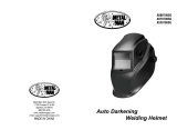
Auto-Darkening
Welding Helmet
User Manual

2
Table of Contents
SECTION 1 - WELDING HELMET SAFETY PRECAUTIONS - READ BEFORE USING ................ 1
1-1. Symbol Usage........................................................................................................................ 1
1-2. Arc Welding Hazards .......................................................................................................... 1-2
1-3. Lens Shade Selection Table ................................................................................................. 3
SECTION 2 - SPECIFICATIONS .................................................................................................... 4
SECTION 3 - OPERATING INSTRUCTIONS .................................................................................. 5
3-1. Helmet Controls .................................................................................................................... 5
3-2. Low Battery Indicator ............................................................................................................ 5
3-3. Weld On/Grind On Switch..................................................................................................... 6
3-4. Lens Delay Control ................................................................................................................ 6
3-5. Variable Shade Control (No. 9-13) ....................................................................................... 7
3-6. Sensitivity Control ................................................................................................................. 8
SECTION 4 - ADJUSTING THE HEADGEAR ................................................................................. 9
SECTION 5 - REPLACING THE LENS COVERS ..........................................................................10
5-1. Replacing the Outside Lens Cover .....................................................................................10
5-2. Replacing the Inside Lens Cover ........................................................................................11
5-3. Removing Auto-Darkening Lens Assembly .......................................................................12
SECTION 6 - REPLACING THE BATTERY ...................................................................................13
SECTION 7 - INSTALLING OPTIONAL MAGNIFYING LENS .......................................................13
SECTION 8 - MAINTENANCE .....................................................................................................13
SECTION 9 - TROUBLESHOOTING ............................................................................................14
SECTION 10 - PARTS LIST .........................................................................................................15
SECTION 11 - LIMITED WARRANTY..........................................................................................16

1
1. Welding Helmet Safety Precautions
- Read before Using
Protect yourself and others from injury - read, follow, and save
these important safety precautions and operating instructions.
DANGER! Indicates a hazardous situation which, if not avoided will result in
death or serious injury. The possible hazards are shown in the adjoining
symbols or explained in the text.
NOTICE: Indicates statements not related to personal injury.
>
Indicates special instructions.
1-1. Symbol Usage
1-2. Arc Welding Hazards
This group of symbols means Warning! Watch
out! ELECTRIC SHOCK, MOVING PARTS, and
HOT PARTS hazards. Consult symbols and
related instructions below for necessary actions
to avoid hazards.
ARC RAYS can Burn Eyes & Skin.
Arc rays from the welding process produce intense visible and invisible (ultraviolet and
infrared) rays that can burn eyes and skin. Sparks y off from the weld.
• Wear a welding helmet tted with a proper shade of lter to protect your face and
eyes when welding or watching. Refer to Lens Shade Selection table in Section 1-4.
• Wear approved safety glasses with side shields under your helmet.
• Use protective screens or barriers to protect others from ash, glare, and sparks;
warn others not to watch the arc.
• Wear body protection made from durable, ame resistant material (leather, heavy
cotton wool). Body protection includes oil-free clothing such as leather gloves, heavy
shirt, cuff-less trousers, high shoes, and a cap.
• Before welding, adjust the auto-darkening lens sensitivity setting to meet the application.
• Stop welding immediately if the auto-darkening lens does not darken when the arc is
struck. See the Owner’s Manual for more information.
Only Qualied Persons Should Install,
Operate, Maintain & Repair this Unit.

2
• Read and follow all labels and the Owner’s Manual carefully before installing,
operating, or servicing unit. Read the safety information at the beginning of the
manual and in each section.
• Use only genuine replacement parts from the manufacturer.
• Perform maintenance and service according to the Owner’s Manuals, industry
standards, and national, state, and local codes.
WELDING HELMETS do not Provide
Unlimited Eye, Ear & Face Protection.
NOISE can Damage Hearing.
READ INSTRUCTIONS.
FUMES & GASES can be Hazardous.
Arc rays from the welding process produce intense visible and invisible (ultraviolet and
infrared) rays that can burn eyes and skin. Sparks y off from the weld.
• Use impact resistant safety spectacles or goggles and ear protection at all times when
using this welding helmet.
• Do not use this helmet while working with or around explosives or corrosive liquids.
• Do not weld in the overhead position while using this helmet.
• Inspect the auto-lens frequently. Immediately replace any scratched, cracked, or pitted
cover lenses or auto-lenses.
Noise from some processes or equipment can damage hearing.
• Wear approved ear protection if noise level is high.
Welding produces fumes and gases. Breathing these fumes and gases can be hazardous
to your health.
• Keep your head out of the fumes. Do not breathe the fumes.
• If inside, ventilate the area and/or use local forced ventilation at the arc to remove
welding fumes and gases. The recommended way to determine adequate ventilation
is to sample for the composition and quantity of fumes and gases to which personnel
are exposed.
• If ventilation is poor, wear an approved air-supplied respirator.
• Read and understand the Safety Data Sheets (SDSs) and the manufacturer’s
instructions for adhesives, coatings, cleaners, consumables, coolants,
degreasers, uxes, and metals.
• Work in a conned space only if it is well ventilated, or while wearing an air-supplied
respirator. Always have a trained watch person nearby. Welding fumes and gases can
displace air and lower the oxygen level causing injury or death. Be sure the breathing air is safe.
• Do not weld in locations near degreasing, cleaning, or spraying operations. The
heat and rays of the arc can react with vapors to form highly toxic and irritating gases.
• Do not weld on coated metals, such as galvanized, lead, or cadmium plated steel,
unless the coating is removed from the weld area, the area is well ventilated, and while
wearing an air-supplied respirator. The coatings and any metals containing these
elements can give off toxic fumes if welded.

3
1-3. Lens Shade Selection Table
*Start with a shade that is too dark to see the weld zone. Then go to a lighter shade which gives a
sufcient view of the weld zone without going below the minimum.
PROCESS
ELECTRODE SIZE
(MM)
ARC
CURRENT IN
AMPS
MIN
PROTECTIVE
SHADE NO.
SUGGESTED
SHADE NO.
(COMFORT)*
Shielded Metal
Arc Welding
(SMAW)
Less than 2.4mm Less than 60 7 -
2.4-4.0mm 60-160 8 10
4.0-6.4mm 160-250 10 12
Gas Metal
Arc Welding
(GMAW)
Flux Cored Arc
Welding (FCAW)
Less than 60 7 -
60-160 10 11
160-300 10 13
Gas Tungsten Arc
Welding (TIG)
Less than 50 8 10
50-150 8 12
150-300 10 13
Arc Carbon Arc
Cutting (CAC-A)
Light Less than 500 10 12
Heavy 500-800 11 13
Plasma Arc
Cutting (PAC)
Less than 20 4 4
20-40 5 5
40-60 6 6
60-80 8 8
80-300 8 9
300-400 9 12
400-600 10 13
Plasma Arc
Welding (PAW)
Less than 20 6 6-8
20-100 8 10
100-400 10 12
400-600 11 13

4
Section 2 - Specications
Cartridge Dimensions 110 x 90 x 10mm
Viewing Field 97 x 46mm
Reaction Time 1/12,000 second
Available Shades Darkened State: 9-13, Light State: 4
Sensors 2 Independent
Operating Temperature
-5°C to +55°C
> When stores in extremely cold temperatures, warm
helmet to ambient temperature before welding.
Storage Temperature
-10°C to +70°C
> When stores in extremely cold temperatures, warm
helmet to ambient temperature before welding.
Power Supply CR2450 Lithium Battery x 1 (Part No. 217043)
Weight 510.3g
Standards
AS/NZS 1338.1 (Auto-Darkening) and
AS/NZS 1337.1B (High Impact)
Warranty 1 Year
Sensitivity Control Light Levels Adjusts for Varying Ambient Light and Welding Arc
Delay Control
Slows Lens Dark-to-Light State Between 0.1 and 1.0
Seconds (Innite Dial Control)
Automatic Power Off Shuts Lens Off 15-20 Minutes After Welding Stops
Low Battery Indicator Red Light Goes on to Indicate Low Battery
Grind Mode Yes

5
Section 3 - Operating Instructions
3-1. Helmet Controls
3-2. Low Battery Indicator
1
6
2
3 4
5
GRIND
ON
WELD
LOW
BATTERY
S
E
N
S
I
T
I
V
I
T
Y
D
E
L
A
Y
MAX
HI
LO
S
H
A
D
E
MIN
1
GRIND
ON
WELD
LOW
BATTERY
S
E
N
S
I
T
I
V
I
T
Y
D
E
L
A
Y
MAX
HI
LO
S
H
A
D
E
MIN
> The Auto-Darkening lens turns on
(darkens) automatically when
welding begins and turns off 15-20
minutes after welding stops.
1. Weld On/Grind On Switch
(See Section 3-3)
2. Variable Shade Control
(See Section 3-5)
3. Sensitivity Control
(See Section 3-6)
4. Delay Control
(See Section 3-4)
5. Battery Compartment
(See Section 6)
6. Low Battery Indicator
(See Section 3-2)
1. Low Battery Indicator
The low battery indicator lights when
2-3 days of battery life remain.
If battery power is low, replace battery
(refer to Section 6).

6
3-3. Weld On/Grind On Switch
3-4. Lens Delay Control
1
GRIND
ON
WELD
LOW
BATTERY
S
E
N
S
I
T
I
V
I
T
Y
D
E
L
A
Y
MAX
HI
LO
S
H
A
D
E
MIN
1
GRIND
ON
WELD
LOW
BATTERY
S
E
N
S
I
T
I
V
I
T
Y
D
E
L
A
Y
MAX
HI
LO
S
H
A
D
E
MIN
1. Weld On/Grind On Switch
Do not weld in the Grind On mode;
the lens will not darken.
For welding applications, move the switch
to the Weld On (up) position. For grinding
applications, move the switch to the
Grind On (down) position.
1. Lens Delay Control
The lens delay control is used to adjust the
time for the lens to switch to the clear state
after welding.
The delay is particularly useful in eliminating
bright rays present in higher amperage
applications where the molten puddle
remains bright momentarily after welding.
Lens delay adjusts from min (0.10 second)
to max (1.0 second).

7
3-5. Variable Shade Control (No. 9-13)
1
GRIND
ON
WELD
LOW
BATTERY
S
E
N
S
I
T
I
V
I
T
Y
D
E
L
A
Y
MAX
HI
LO
S
H
A
D
E
MIN
1. Variable Shade Control (No. 9-13)
Use the control to adjust the lens shade in
the darkened state. Use the table in section
1-4 to select the proper shade control setting
based on your welding process.
Start at shade 12 or 13 and adjust lighter
to suit the welding application and your
personal preference.

8
1
3-6. Sensitivity Control
GRIND
ON
WELD
LOW
BATTERY
S
E
N
S
I
T
I
V
I
T
Y
D
E
L
A
Y
MAX
HI
LO
S
H
A
D
E
MIN
RECOMMENDED SENSITIVITY SETTINGS
Stick Electrode Mid-Range
Short Circuiting (MIG) Low/Mid-Range
Pulsed & Spray (MIG) Mid-Range
Gas Tungsten Arc (TIG) Mid/High-Range
Plasma Arc Cutting/Welding Low/Mid-Range
1. Sensitivity Control
Use control to make the lens
more responsive to different
light levels in various
welding processes.
Use a Mid-Range or
30-50% sensitivity setting
for most applications.
It may be necessary to
adjust helmet sensitivity
to accommodate different
lighting conditions or if lens
is ashing On and Off.
Adjust helmet sensitivity
as follows:
> Adjust helmet sensitivity
in lighting conditions
helmet will be used in.
• Turn sensitivity control
to lowest setting.
• Face the helmet in the
direction of use, exposing
it to the surrounding
light conditions.
• Gradually turn sensitivity
setting clockwise until the
lens darkens, then turn
sensitivity control
counterclockwise until
slightly past setting
where lens clears.
Helmet is ready for use.
Slight readjustment
may be necessary
for certain applications
or if lens is ashing on
and off.

9
Section 4 - Adjusting the Headgear
342
1
> There are four headgear adjustments:
headgear top, tightness, angle
adjustment, and distance
adjustment.
1. Headgear Top
Adjusts headgear for proper depth on
the head to ensure correct balance
and stability.
2. Headgear Tightness
To adjust, push in the adjusting knob
located on the back of the headgear and
turn left or right to desired tightness.
> If adjustment is limited, it may
be necessary to remove the
comfort cushion.
3. Distance adjustment
Adjusts the distance between the face and
the lens. To adjust, loosen both outside
tension knobs and press inward to free
from adjustment slots. Move forward or
back to desired position and re-tighten.
(Both sides must be equally positioned
for proper vision).
4. Angle Adjustment
Four pins on the right side of the headband
top provide adjustment for the forward tilt
of the helmet. To adjust, loosen the right
outside tension adjustment knob then lift
on the control arm tab and move it to the
desired position. Re-tighten tension
adjustment knob.
> When using the back distance
adjustment positions, only the back
three angle adjustment pins can
be used.

10
5
4
3 2
1
Section 5 - Replacing the Lens Covers
5-1. Replacing the Outside Lens Cover
Never use the
auto-darkening lens
without the inside and
outside lens covers
properly installed. Welding
spatter will damage the
auto-darkening lens and
void the warranty.
1. Auto-Darkening Lens
Retainer Clips.
2. Auto-Darkening
Lens Retainer.
3. Auto-Darkening
Lens Assembly.
4. Outside Protective
Lens (Clear).
5. Gasket.
Place helmet upside down
on a at surface.
Adjust or remove headgear
to improve access to lens
assembly.
Gently release the top and
bottom auto-darkening lens
retainers located inside the
helmet. Lift out auto-
darkening lens assembly.
Hold assembly and press
outside lens and gasket
from front. (Assembly comes
out through the back of the
helmet).
Replace clear lens with
new lens (Reuse the
rubber gasket).
> Use the rubber gasket to
keep weld spatter away
from the auto-darkening
lens.
Reinstall new outside
protective lens with gasket
and reinstall auto darkening
lens in the plastic lens
retainer.
Reinstall the retainer
and secure the top and
bottom lens retainer clips.
> The outside lens
gasket must be
correctly installed for
maximum lens
protection.

11
5-2. Replacing the Inside Lens Cover
2
3
4
1
Never use the
auto-darkening lens
without the inside and
outside lens covers
properly installed. Welding
spatter will damage the
auto-darkening lens and
void the warranty.
1. Auto-Darkening Lens
Retainer Clips.
2. Auto-Darkening
Lens Assembly.
3. Auto-Darkening
Lens Retainer.
4. Inside Protective
Lens (Clear).
Place helmet upside down
on a at surface.
Adjust or remove headgear
to improve access to lens
assembly.
Gently release the top and
bottom auto-darkening
lens retainers located
inside the helmet. Lift out
auto-darkening lens
assembly.
Gently remove auto-
darkening lens assembly
from retainer by releasing
the four tabs.
Remove inside protective
lens at the marked
locations and replace with
new lens.
> Use the rubber gasket
to keep weld spatter
away from the
auto-darkening lens.

12
5-3. Removing Auto-Darkening Lens Assembly
2 3
1
Never use the
auto-darkening lens
without the inside and
outside lens covers
properly installed. Welding
spatter will damage the
auto-darkening lens and
void the warranty.
1. Auto-Darkening Lens
Retainer Clips.
2. Auto-Darkening
Lens Assembly.
3. Auto-Darkening
Lens Retainer.
Place helmet upside down
on a at surface.
Adjust or remove headgear
to improve access to lens
assembly.
Gently release the top and
bottom auto-darkening
lens retainers located
inside the helmet. Lift out
auto-darkening lens assembly.
Gently remove
auto-darkening lens assembly
from retainer by releasing
the four tabs.
Reinstall lens assembly in
reverse order of removal.

13
Section 6 - Replacing the Battery
Section 7 - Installing Optional Magnifying Lens
Section 8 - Maintenance
1. Battery Cover
Remove battery by turning
battery cover counter clockwise.
Replace with CR2450 lithium battery.
WIA recommend using the Panasonic
battery, as the side edge and shoulder
are straight and provide good connection
to battery terminals. Battery is available
as spare part number 217043
> Be sure positive (+) side of the battery
faces up (toward inside of helmet).
1. Optional Magnifying Lens
Release lower lens retainer clip.
Starting at the bottom, slide magnifying
lens into the helmet retaining brackets.
Align the magnifying lens with the
auto-darkening lens assembly.
Reverse procedure to remove
magnifying lens.
> To prevent lens fogging, install
atsideofmagnifyinglenstoward
auto-darkening lens.
NOTICE: Never use solvents or abrasive cleaning detergents.
NOTICE: Do not immerse the lens assembly in water.
The helmet requires little maintenance, however for best performance clean after each use.
Using a soft cloth dampened with a mild soap and water solution, wipe the cover lenses
clean. Allow to air dry. Occasionally, the lter lens and sensors should be cleaned by gently
wiping with a soft, dry cloth.
1
GRIND
ON
WELD
LOW
BATTERY
S
E
N
S
I
T
I
V
I
T
Y
D
E
L
A
Y
MAX
HI
LO
S
H
A
D
E
MIN
1

14
Section 9 - Troubleshooting
TROUBLE REMEDY
Auto lens not on – Auto-lens will
not darken momentarily when
exposed to welding arc.
Check batteries and verify they are in good condition
and installed properly. Also, check battery surfaces
and contacts and clean if necessary. Check battery
for proper contact and gently adjust contact points if
necessary. This is particularly important if the helmet
has been dropped.
Auto-lens not switching –
Auto-lens stays light and will not
darken when welding or cutting.
Stop welding immediately.
Make sure the lens is in the Weld On mode. When in
the Weld On mode the lens will darken for welding
applications. Do not weld in the Grind On mode; the
lens will not darken.
Make sure the lens is turned On. If power is on,
review the sensitivity recommendations and adjust
sensitivity. Clean lens cover and sensors of any
obstructions. Make sure the sensors are facing the
arc; angles of 45 or more may not allow the arc light
to reach the sensors.
Auto-lens not switching –Auto-lens
stays dark after the weld arc is ex-
tinguished, or the auto-lens stays
dark when no arc is present.
Fine-tune the sensitivity setting by making small
adjustments to the control by turning it toward the
“min” setting. In extreme light conditions, it may be
necessary to reduce the surrounding light levels.
Sections of the auto-lens
are not going dark, distinct lines
separate the light and dark areas.
Stop welding immediately.
The auto-lens may be cracked which can be caused
by the impact of dropping the helmet. Weld spatter on
the auto lens may also cause cracking. (The lens may
need to be replaced; most cracked lenses are not
covered by warranty).
Switching or Flickering –
The auto-lens darkens then
lightens while the welding
arc is present.
Review the sensitivity setting recommendations and
increase the sensitivity if possible. Be sure the arc
sensors are not being blocked from direct access to
the arc light. Check the lens cover for dirt and spatter
that may be blocking the arc sensors. Increasing Lens
Delay 0.1–0.3 second may also reduce switching.
Inconsistent or lighter auto-lens
shading in the dark-state,
noticeable on the outside edges
and corners.
Referred to as an angle of view effect, auto-darkening
lenses have an optimum viewing angle. The optimum
viewing angle is perpendicular or 90 degrees to the
surface of the auto-lens. When that angle of view
varies in the dark-state, welders may notice slightly
lighter areas at the outside edges and the corners of
the lens. This is normal and does not represent any
health or safety hazard. This effect may also be more
noticeable in applications where magnifying lenses
are used.

15
Section 10 - Parts List
FIGURE 10-1. AUTO-DARKENING WELDING HELMET
1. Kit, Lens Holder (235661)
2. Outside Cover Lens (235665P)
3. Inside Cover Lens (770237P)
4. Replacement Auto-Darkening Lens (235662)
5. Ratchet Headgear Assembly (770246)
6. Magnifying Lens 1.5x (212238P)
Magnifying Lens 2.0x (212240P)
Magnifying Lens 2.5x (212242P)
7. Gasket Cover Lens (235664)
Not Shown. Lithium Battery (217043)
1
3
4
2
7
6
5

16
Section 11 - Limited Warranty
LIMITED WARRANTY
Welding Industries of Australia (WIA) warrants to the original retail purchaser that the
WIA BlueFX auto-darkening welding helmet purchased (Product) will be free from defects in
materials and workmanship for a period of 1 year from the date of purchase of the Product
by the customer. If a defect in material or workmanship becomes evident during that period,
Welding Industries of Australia will, at its option, either:
• Repair the Product (or pay for the costs of repair of the Product); or
• Replace the Product.
In the event of such a defect, the customer should return the Product to the original place of
purchase, with proof of purchase, or contact Welding Industries of Australia on 1300 300 884.
Any handling and transportation costs (and other expenses) incurred in claiming under this
warranty are not covered by this warranty and will not be borne by Welding Industries of
Australia. Welding Industries of Australia will return the replacement Product (if found faulty)
or the original product (if not faulty) freight free to the customer.
This warranty covers the auto-darkening lens only, and does not extend to the helmet shell,
headgear or accessories included in the original purchase package.
The obligation of Welding Industries of Australia under this warranty is limited to the
circumstances set out above and is subject to:
• The customer being able to evidence the acquisition of the Product, the purchase price
paid for the Product and the relevant defect in materials or workmanship;
• The Product not having been altered, tampered with or otherwise dealt with by any person
in a manner other than as intended in respect of the relevant Product; and
• The Product not having been used or applied in a manner that is contrary to customary
usage or application for the relevant Product or contrary to any stated instructions or
specication of Welding Industries of Australia.
Our goods come with guarantees that cannot be excluded under the Australian Consumer
Law. You are entitled to a replacement or refund for a major failure and for compensation for
any other reasonably foreseeable loss or damage. You are also entitled to have the goods
repaired or replaced if the goods fail to be of acceptable quality and the failure does not
amount to a major failure. The benets given by this warranty are in addition to other rights
and remedies which may be available to the customer under any law in relation to goods
and services to which this warranty relates.
Warranty provided by:
Welding Industries of Australia (ABN 63 004 235 063)
A Division of ITW Australia Pty Ltd
5 Allan Street, Melrose Park, South Australia, 5039
Email: info@welding.com.au
Telephone: 1300 300 884
welding.com.au

17
Notes

welding.com.au
1300 300 884
235663 ISS 1 JAN 2017
/