Page is loading ...

Copyright © 2002 ROLAND CORPORATION
All rights reserved. No part of this publication may be reproduced in any form without the
written permission of ROLAND CORPORATION.
Roland Web site: http://www.roland.co.jp/
Before using this unit, carefully read the sections entitled: “IMPORTANT SAFETY
INSTRUCTIONS” (Owner’s Manual p. 2), “USING THE UNIT SAFELY” (Owner’s
Manual p. 3), and “IMPORTANT NOTES” (Owner’s Manual p. 4). These sections
provide important information concerning the proper operation of the unit.
Additionally, in order to feel assured that you have gained a good grasp of every
feature provided by your new unit, User Guide, Owner’s Manual, and Appendices
should be read in its entirety. These manuals should be saved and kept on hand as a
convenient reference.
02902323 ’04-1-3KS
Appendices
To resize thickness, move all items on the front cover to left or right.
• Iomega is a registered trademark of Iomega Corporation.
• ZIP is a trademark of Iomega Corporation.
• All product names mentioned in this document are trademarks or registered trademarks of their respective owners.
Copyright
• Unauthorized recording, distribution, sale, lending, public performance, broadcasting, or the like, in whole or
in part, of a work (musical composition, video, broadcast, public performance, or the like) whose copyright is
held by a third party is prohibited by law.
• When exchanging audio signals through a digital connection with an external instrument, this unit can
perform recording without being subject to the restrictions of the Serial Copy Management System (SCMS).
This is because the unit is intended solely for musical production, and is designed not to be subject to restric-
tions as long as it is used to record works (such as your own compositions) that do not infringe on the
copyrights of others. (SCMS is a feature that prohibits second-generation and later copying through a digital
connection. It is built into MD recorders and other consumer digital-audio equipment as a copyright-
protection feature.)
• Do not use this unit for purposes that could infringe on a copyright held by a third party. Roland assumes no
responsibility whatsoever with regard to any infringements of third-party copyrights arising through your
use of this unit.
About the License Agreement
• The VS-2480 and its CD-R capability are designed to allow you to reproduce material to which you have copyright, or
material which the copyright owner has granted you permission to copy. Accordingly, reproduction of Music CD or
other copyrighted material without permission of the copyright owner avoiding technical prohibiting features of
second-generation and later copying like SCMS or others constitutes copyright infringement and may incur penalties
even in case such reproduction is for your own personal use and enjoyment (private use). Consult a copyright specialist
or special publications for more detailed information on obtaining such permission from copyright holders.
Version 2.0
Appendices

Information
When you need repair service, call your nearest Roland Service Center or authorized Roland distributor in your country as
shown below.
As of November 1, 2003 (Roland)
ARGENTINA
Instrumentos Musicales S.A.
Av.Santa Fe 2055
(1123) Buenos Aires
ARGENTINA
TEL: (011) 4508-2700
BRAZIL
Roland Brasil Ltda
Rua San Jose, 780 Sala B
Parque Industrial San Jose
Cotia - Sao Paulo - SP, BRAZIL
TEL: (011) 4615 5666
MEXICO
Casa Veerkamp, s.a. de c.v.
Av. Toluca No. 323, Col. Olivar
de los Padres 01780 Mexico D.F.
MEXICO
TEL: (55) 5668-6699
PANAMA
SUPRO MUNDIAL, S.A.
Boulevard Andrews, Albrook,
Panama City, REP. DE PANAMA
TEL: 315-0101
U. S. A.
Roland Corporation U.S.
5100 S. Eastern Avenue
Los Angeles, CA 90040-2938,
U. S. A.
TEL: (323) 890 3700
VENEZUELA
Musicland Digital C.A.
Av. Francisco de Miranda,
Centro Parque de Cristal, Nivel
C2 Local 20 Caracas
VENEZUELA
TEL: (212) 285-8586
AUSTRALIA
Roland Corporation
Australia Pty., Ltd.
38 Campbell Avenue
Dee Why West. NSW 2099
AUSTRALIA
TEL: (02) 9982 8266
NEW ZEALAND
Roland Corporation Ltd.
32 Shaddock Street, Mount Eden,
Auckland, NEW ZEALAND
TEL: (09) 3098 715
HONG KONG
Tom Lee Music Co., Ltd.
Service Division
22-32 Pun Shan Street, Tsuen
Wan, New Territories,
HONG KONG
TEL: 2415 0911
Parsons Music Ltd.
8th Floor, Railway Plaza, 39
Chatham Road South, T.S.T,
Kowloon, HONG KONG
TEL: 2333 1863
INDIA
Rivera Digitec (India) Pvt. Ltd.
409, Nirman Kendra Mahalaxmi
Flats Compound Off. Dr. Edwin
Moses Road, Mumbai-400011,
INDIA
TEL: (022) 2493 9051
INDONESIA
PT Citra IntiRama
J1. Cideng Timur No. 15J-150
Jakarta Pusat
INDONESIA
TEL: (021) 6324170
MALAYSIA
BENTLEY MUSIC SDN BHD
140 & 142, Jalan Bukit Bintang
55100 Kuala Lumpur,MALAYSIA
TEL: (03) 2144-3333
PHILIPPINES
G.A. Yupangco & Co. Inc.
339 Gil J. Puyat Avenue
Makati, Metro Manila 1200,
PHILIPPINES
TEL: (02) 899 9801
SINGAPORE
Swee Lee Company
150 Sims Drive,
SINGAPORE 387381
TEL: 6846-3676
TAIWAN
ROLAND TAIWAN
ENTERPRISE CO., LTD.
Room 5, 9fl. No. 112 Chung Shan
N.Road Sec.2, Taipei, TAIWAN,
R.O.C.
TEL: (02) 2561 3339
THAILAND
Theera Music Co. , Ltd.
330 Verng NakornKasem, Soi 2,
Bangkok 10100, THAILAND
TEL: (02) 2248821
BAHRAIN
Moon Stores
No.16, Bab Al Bahrain Avenue,
P.O.Box 247, Manama 304,
State of BAHRAIN
TEL: 211 005
VIETNAM
Saigon Music
Suite DP-8
40 Ba Huyen Thanh Quan Street
Hochiminh City, VIETNAM
Tel: (08) 930-1969
JORDAN
AMMAN Trading Agency
245 Prince Mohammad St.,
Amman 1118, JORDAN
TEL: (06) 464-1200
KUWAIT
Easa Husain Al Yousifi Est.
Abdullah Salem Street,
Safat, KUWAIT
TEL: 243-6399
LEBANON
Chahine S.A.L.
Gerge Zeidan St., Chahine Bldg.,
Achrafieh, P.O.Box: 16-5857
Beirut, LEBANON
TEL: (01) 20-1441
QATAR
Al Emadi Co. (Badie Studio
& Stores)
P.O. Box 62, Doha, QATAR
TEL: 4423-554
SAUDI ARABIA
aDawliah Universal
Electronics APL
Corniche Road, Aldossary Bldg.,
1st Floor, Alkhobar,
SAUDI ARABIA
P.O.Box 2154, Alkhobar 31952
SAUDI ARABIA
TEL: (03) 898 2081
TURKEY
Ant Muzik Aletleri Ithalat
Ve Ihracat Ltd Sti
Siraselviler Caddesi Siraselviler
Pasaji No:74/20
Taksim - Istanbul, TURKEY
TEL: (0212) 2499324
U.A.E.
Zak Electronics & Musical
Instruments Co. L.L.C.
Zabeel Road, Al Sherooq Bldg.,
No. 14, Grand Floor, Dubai, U.A.E.
TEL: (04) 3360715
EGYPT
Al Fanny Trading Office
9, EBN Hagar A1 Askalany Street,
ARD E1 Golf, Heliopolis,
Cairo 11341, EGYPT
TEL: 20-2-417-1828
REUNION
Maison FO - YAM Marcel
25 Rue Jules Hermann,
Chaudron - BP79 97 491
Ste Clotilde Cedex,
REUNION ISLAND
TEL: (0262) 218-429
SOUTH AFRICA
That Other Music Shop
(PTY) Ltd.
11 Melle St., Braamfontein,
Johannesbourg, SOUTH AFRICA
P.O.Box 32918, Braamfontein 2017
Johannesbourg, SOUTH AFRICA
TEL: (011) 403 4105
Paul Bothner (PTY) Ltd.
17 Werdmuller Centre,
Main Road, Claremont 7708
SOUTH AFRICA
P.O.BOX 23032, Claremont 7735,
SOUTH AFRICA
TEL: (021) 674 4030
CYPRUS
Radex Sound Equipment Ltd.
17, Diagorou Street, Nicosia,
CYPRUS
TEL: (022) 66-9426
DENMARK
Roland Scandinavia A/S
Nordhavnsvej 7, Postbox 880,
DK-2100 Copenhagen
DENMARK
TEL: 3916 6200
FRANCE
Roland France SA
4, Rue Paul Henri SPAAK,
Parc de l'Esplanade, F 77 462 St.
Thibault, Lagny Cedex FRANCE
TEL: 01 600 73 500
FINLAND
Roland Scandinavia As,
Filial Finland
Elannontie 5
FIN-01510 Vantaa, FINLAND
TEL: (0)9 68 24 020
GERMANY
Roland Elektronische
Musikinstrumente HmbH.
Oststrasse 96, 22844 Norderstedt,
GERMANY
TEL: (040) 52 60090
GREECE
STOLLAS S.A.
Music Sound Light
155, New National Road
Patras 26442, GREECE
TEL: 2610 435400
HUNGARY
Roland East Europe Ltd.
Warehouse Area ‘DEPO’ Pf.83
H-2046 Torokbalint, HUNGARY
TEL: (23) 511011
IRELAND
Roland Ireland
G2 Calmount Park, Calmount
Avenue, Dublin 12
Republic of IRELAND
TEL: (01) 4294444
ITALY
Roland Italy S. p. A.
Viale delle Industrie 8,
20020 Arese, Milano, ITALY
TEL: (02) 937-78300
NORWAY
Roland Scandinavia Avd.
Kontor Norge
Lilleakerveien 2 Postboks 95
Lilleaker N-0216 Oslo
NORWAY
TEL: 2273 0074
POLAND
MX MUSIC SP.Z.O.O.
UL. Gibraltarska 4.
PL-03664 Warszawa POLAND
TEL: (022) 679 44 19
PORTUGAL
Tecnologias Musica e Audio,
Roland Portugal, S.A.
Cais Das Pedras, 8/9-1 Dto
4050-465 PORTO
PORTUGAL
TEL: (022) 608 00 60
RUSSIA
MuTek
3-Bogatyrskaya Str. 1.k.l
107 564 Moscow, RUSSIA
TEL: (095) 169 5043
SPAIN
Roland Electronics
de España, S. A.
Calle Bolivia 239, 08020
Barcelona, SPAIN
TEL: (93) 308 1000
SWITZERLAND
Roland (Switzerland) AG
Landstrasse 5, Postfach,
CH-4452 Itingen,
SWITZERLAND
TEL: (061) 927-8383
SWEDEN
Roland Scandinavia A/S
SWEDISH SALES OFFICE
Danvik Center 28, 2 tr.
S-131 30 Nacka SWEDEN
TEL: (0)8 702 00 20
UKRAINE
TIC-TAC
Mira Str. 19/108
P.O. Box 180
295400 Munkachevo, UKRAINE
TEL: (03131) 414-40
UNITED KINGDOM
Roland (U.K.) Ltd.
Atlantic Close, Swansea
Enterprise Park, SWANSEA
SA7 9FJ,
UNITED KINGDOM
TEL: (01792) 702701
KOREA
Cosmos Corporation
1461-9, Seocho-Dong,
Seocho Ku, Seoul, KOREA
TEL: (02) 3486-8855
AUSTRIA
Roland Austria GES.M.B.H.
Siemensstrasse 4, P.O. Box 74,
A-6063 RUM, AUSTRIA
TEL: (0512) 26 44 260
BELGIUM/HOLLAND/
LUXEMBOURG
Roland Benelux N. V.
Houtstraat 3, B-2260, Oevel
(Westerlo) BELGIUM
TEL: (014) 575811
CZECH REP.
K-AUDIO
Kardasovska 626.
CZ-198 00 Praha 9,
CZECH REP.
TEL: (2) 666 10529
AFRICA
CHILE
Comercial Fancy S.A.
Rut.: 96.919.420-1
Nataniel Cox #739, 4th Floor
Santiago - Centro, CHILE
TEL: (02) 688-9540
URUGUAY
Todo Musica S.A.
Francisco Acuna de Figueroa 1771
C.P.: 11.800
Montevideo, URUGUAY
TEL: (02) 924-2335
EUROPE
AUSTRALIA/
NEW ZEALAND
ASIA
CENTRAL/LATIN
AMERICA
NORTH AMERICA
MIDDLE EAST
AFRICA
EL SALVADOR
OMNI MUSIC
75 Avenida Norte y Final
Alameda Juan Pablo ,
Edificio No.4010 San Salvador,
EL SALVADOR
TEL: 262-0788
ROMANIA
FBS LINES
Piata Libertatii 1,
535500 Gheorgheni, ROMANIA
TEL: (266) 364 609
PARAGUAY
Distribuidora De
Instrumentos Musicales
J.E. Olear y ESQ. Manduvira
Asuncion PARAGUAY
TEL: (021) 492-124
COSTA RICA
JUAN Bansbach
Instrumentos Musicales
Ave.1. Calle 11, Apartado 10237,
San Jose, COSTA RICA
TEL: 258-0211
CRISTOFORI MUSIC PTE
LTD
Blk 3014, Bedok Industrial Park E,
#02-2148, SINGAPORE 489980
TEL: 6243-9555
IRAN
MOCO, INC.
No.41 Nike St., Dr.Shariyati Ave.,
Roberoye Cerahe Mirdamad
Tehran, IRAN
TEL: (021) 285-4169
ISRAEL
Halilit P. Greenspoon &
Sons Ltd.
8 Retzif Ha'aliya Hashnya St.
Tel-Aviv-Yafo ISRAEL
TEL: (03) 6823666
SYRIA
Technical Light & Sound
Center
Khaled Ebn Al Walid St.
Bldg. No. 47, P.O.BOX 13520,
Damascus, SYRIA
TEL: (011) 223-5384
CANADA
Roland Canada Music Ltd.
(Head Office)
5480 Parkwood Way Richmond
B. C., V6V 2M4 CANADA
TEL: (604) 270 6626
Roland Canada Music Ltd.
(Toronto Office)
170 Admiral Boulevard
Mississauga On L5T 2N6
CANADA
TEL: (905) 362 9707
CHINA
Roland Shanghai Electronics
Co.,Ltd.
5F. No.1500 Pingliang Road
Shanghai 200090, CHINA
TEL: (021) 5580-0800
Roland Shanghai Electronics
Co.,Ltd.
(BEIJING OFFICE)
10F. No.18 Anhuaxili
Chaoyang District, Beijing 100011
CHINA
TEL: (010) 6426-5050
Roland Shanghai Electronics
Co.,Ltd.
(GUANGZHOU OFFICE)
2/F., No.30 Si You Nan Er Jie Yi
Xiang, Wu Yang Xin Cheng,
Guangzhou 510600, CHINA
Tel: (020) 8736-0428
2
To resize thickness, move all items on the front cover to left or right.
About MIDI .............................................................................................. 3
About SCSI ............................................................................................. 4
Troubleshooting..................................................................................... 5
Error Messages ...................................................................................... 9
Glossary................................................................................................ 12
Shortcut Key Operations..................................................................... 16
Parameter List ...................................................................................... 18
Preset Patch List .................................................................................. 27
Algorithm List....................................................................................... 33
MIDI Implementation ............................................................................ 88
Track Sheet........................................................................................... 95
SPECIFICATIONS ................................................................................. 98
Index.................................................................................................... 100
Contents

3
About MIDI
About MIDI
This section explains the basic concepts of MIDI, and how the
VS-2480/2480CD handles MIDI messages.
What is MIDI
MIDI stands for
Musical Instrument Digital Interface
. It is a
worldwide standard that allows electronic musical
instruments and personal computer to exchange musical
performance data and messages such as sound selections.
Any MIDI-compatible device can transmit musical data (as
appropriate for the type of device) to any other MIDI-
compatible device, regardless of its manufacturer or model
type.
MIDI connectors
MIDI messages (the data handled by MIDI) are transmitted
and received using the following three types of connectors.
On the VS-2480/2480CD, MIDI OUT and MIDI THRU are
handled by a single connector, which can be switched to act
as the desired connector.
MIDI IN:
This receives MIDI messages from external
MIDI devices.
MIDI OUT:
This transmits MIDI messages from the
VS-2480/2480CD.
MIDI THRU:
This re-transmits all MIDI messages that were
received at MIDI IN, without modifying them.
MIDI channels
MIDI is able to send information over a single MIDI cable
independently to two or more MIDI devices. This is made
possible by the concept of MIDI channels. You can think of
MIDI channels as being somewhat similar in function to the
channels on a television. By changing the channel of a TV set,
you can view a variety of programs being transmitted by
different broadcast stations. This is because data is received
only from the transmitter whose channel is selected on the
receiver.
In the same way, a MIDI device whose receive channel is set
to “1” will receive only the data being transmitted by another
MIDI device whose transmit channel is also set to “1.”
MIDI messages
The VS-2480/2480CD uses the following types of MIDI
message.
Note messages:
These messages are used to play notes. On a keyboard, these
message transmit the key (note number) that was pressed,
and how strongly it was pressed (velocity). On the VS-2480/
2480CD, these messages are used when you use a MIDI
sound source to play the metronome sound.
Control Change messages:
In general, these messages are used to transmit information
such as vibrato, hold, and volume etc., that makes a
performance more expressive. The various functions are
differentiated by a controller number from 0–127, and the
controller number is defined for each function. The functions
that can be controlled on any given device will depend on
that device.
On the VS-2480/2480CD, these messages can be transmitted
to external MIDI devices by V.Fader function.
Exclusive messages:
Unlike note messages and control change messages,
exclusive messages are used to transmit settings that are
unique to a particular device. On the VS-2480/2480CD, they
can be used to control VS-2480/2480CD mixer parameter,
when it receives exclusive messages.
Exclusive messages intended for different units are
distinguished by their Device ID, rather than by MIDI
channel. When exclusive messages are to be transmitted or
received, you must set the Device ID of both units to a
matching setting.
MIDI Implementation Chart
MIDI allows a variety of electronic musical instruments to
communicate with each other. However it is not necessarily
the case that all devices will be able to communicate using all
types of MIDI message. They can only communicate using
those types of MIDI message that they have in common.
Each owner’s manual for a MIDI device includes a MIDI
Implementation Chart. This chart shows you at a glance the
types of MIDI message that can be transmitted and received.
By comparing the implementation charts of two devices, you
will be able to see the types of message with which they will
be able to communicate.

4
About SCSI
SCSI stands for
Small Computer System Interface
. It is a
data transfer standard that allows large amounts of data to
be sent and received. The VS-2480 comes prepared with a
SCSI connectors allowing you to connect external SCSI
devices such as hard disks and Zip drives. This section
describes the procedures and precautions taken when using
these devices.
Disk drives are precision devices. If they are connected or
used incorrectly, not only may they fail to operate correctly,
but the data on the disk can be lost or, in the worst case, the
disk drive itself may be damaged. Please be sure to read the
manual for your disk drive.
A disk drive being used for the first time with the VS-2480
must be formatted by the VS-2480. When a disk drive is
formatted, all data on that disk drive is lost. Before using a
disk drive that has been used by another device, make sure
that it is all right to erase the data.
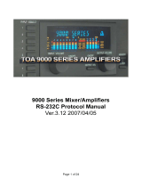
About Connections
Up to 7 disk drives can be connected to the SCSI connector of
the VS-2480. Use SCSI cable to connect the disk drives,
connecting as shown below. SCSI connectors are not
distinguished by input and output ends, so you may attach
either end of the cable to the devices. Devices connected in
this fashion are referred to as a
SCSI chain
or
daisy chain
.
fig.01-01
• The VS-2480 features a DB-25 type connector (female).
After checking your disk drive to see what kind of SCSI
connector it uses, connect it with the appropriate cable.
• Keep SCSI cables as short as possible, and use only
cables which have an impedance that is compatible with
the SCSI standard (110
Ω
+/-10%), and that are
completely shield.
• Do not allow the total length of all SCSI cables
connecting the chain of disk drives to exceed 6.5 meters.
• Do not connect or disconnect SCSI cables when the
power of any device is turned on.
About Terminators
To protect against return noise, the device at each end of a
SCSI chain must have a terminating resistance. This is
referred to as a
terminator
. Since the VS-2480 is one end of
the SCSI chain, its internal terminator is normally in effect.
Connect a terminator only to the last external drive in the
chain. There are two types of terminators, those that can be
switched on and off (internal) and those that are attached
using SCSI connections (externally attached). Select the
method appropriate for the disk drive you are using.
• Your disk drive may feature a terminator switch that is
normally left in the “On” position (i.e., the terminator is
usually in effect). Use this type of device as the last piece
in a daisy chain.
• Do not use double terminators. For example, don’t attach
an external terminator to a disk drive that already has
and internal terminator.
Active Terminators
If you are using an external terminator, we recommend that
you make it an active terminator. In this case, if you are using
a disk drive that allows you to turn the power to the
terminator on and off, be sure to turn this power on. For
details on attaching an active terminator, refer to the owner’s
manual for your disk drive.
Active Terminator (p. 12), Terminator Power (p. 15)
About SCSI ID Numbers
Each disk drive is distinguished by its SCSI ID number (0–7).
This means that when two or more disk drives are connected,
you must make settings so that the SCSI ID numbers of the
disk drives do not conflict (coincide). If the SCSI ID numbers
conflict, the VS-2480 will not be able to correctly recognize
the disk drives.
With the factory settings, the VS-2480 is set to SCSI ID
number 7. Set the disk drives you are connected to ID
numbers other than 7.
VS-2480 Disk Drive1
(Zip Drive, etc)
Disk Drive2
(Zip Drive, etc)
Disk Drive7
(CD-RW Drive, etc)

5
Troubleshooting
Troubleshooting
When the VS-2480/2480CD does not perform the way you
expect, check the following points before you suspect a
malfunction. If this does not resolve the problem, contact
servicing by your dealer or qualified Roland Service Center.
Recording and Playback
No Sound
• The power of the VS-2480/2480CD and the connected
devices is not turned on.
• The audio cables are not connected correctly.
• The audio cables are broken.
• The volume is turned down on the connected mixer or
amp.
• Each Levels of the VS-2480/2480CD is turned down.
Channel fader
Master fader
MONITOR knob
PHONES knob
• The output jacks which are connected are different than
the output jacks selected in the master section of the
mixer.
• Short phrases less than 0.5 seconds cannot be played
back.
• The volume level of the instrument connected to
the VS-2480 is too low.
→
Could you be using a connection cable that contains
a resistor? Use a connection cable that does not
contain a resistor.
•I can’t record or play back, even when I press
[PLAY]
.
→
Does the he PLAY indicator just blink green? When
the EXT SYNC indicator is on, the VS-2480 is
receiving MTC receive standby messages from the
external MIDI device. Operate the external MIDI
device or press
[STOP]
.
→
When “POWER OFF/RESTART” appears in the
display it means that the shutdown procedure is
being performed. Hold down
[SHIFT]
and press
[PLAY (RESTART)]
. This restarts the VS-2480/
2480CD.
A specific channels does not sound
• The input mixer or the track mixer has not selected
correctly.
• The volume level of the channel is turned down.
• The track status is off (the STATUS indicator is off).
• The Solo or Mute function is being used.
• The project with a recording mode of “M16” or “CDR” is
selected.
→
When “M16” is selected, the VS-2480/2480CD will
function as a 16 track recorder. When “CDR” is
selected, the VS-2480/2480CD will function as a
eight-pair stereo recorder (channel link is on: track
1/2, 3/4–). Track 17–24 cannot be used.
For details refer to the “Main feature: Disk Recorder
Section”(Owner’s Manual).
Cannot record
• The recording track has not been selected (the STATUS
indicator is not blinking red).
• Recording source tracks, playback tracks, or effects have
not been assigned.
• The disk drive has insufficient capacity.
• The project has an insufficient number of events.
• The number of tracks which can be simultaneously
recorded will decrease.
→
Depending on the organization of the song data or
the disk drive performance etc., the number of tracks
which can be simultaneously recorded or played
back may be limited.
→
When the recording mode is "M16" or "CDR," up to
16 tracks can be recorded simultaneously.
→
when set the Sample Rate to more than “64 kHz” or
set the Vari Pitch to “On,” the number of tracks
which can be simultaneously recorded may be
limited.
For details refer to the “Main feature: Disk Recorder
Section”(Owner’s Manual).

6
Troubleshooting
Cannot record digitally
• The CD player’s digital connection is not accepted.
• The
MASTER CLOCK
is set to “INT”.
• The DIGITAL IN connector (optical/coaxial/R-BUS)
was not properly selected.
• The sampling rate of the recording destination project is
different than the sampling rate of the digital audio
device.
→
Match the sample rate setting of the digital audio
device to the setting of the project. If it is not
possible to change the sample rate of the digital
audio device, create a new project with that sample
rate.
• The digital signal is not being transmitted from the
digital audio device.
→
Some digital audio devices do not output a digital
signal unless they are in play mode. If this is the
case, put your digital audio device in standby
(pause) mode before putting the VS-2480/2480CD
into record mode.
• The digital signal format is different.
→
Some digital audio devices may use a special digital
signal format. Please connect to a digital audio
device that is compatible with S/P DIF.
Noise and distortion appear in the
recorded sound
• Input sensitivity settings are incorrect.
→
If input sensitivity settings are too high, the
recorded sound will be distorted. Conversely, if they
are too low, the recorded sound will be obscured by
noise. Adjust the SENS knobs so that the level
meters move at as high a level as possible, within the
range of -12 dB to 0 dB.
• The equalizer is being used with the input mixer.
→
Some equalizer settings may cause the sound to
distort even if the channel number of the peak
indicator does not reverse. Readjust the equalizer.
• “ATT” (Attenuator) setting is incorrect.
→
If noise or distortion occurred as a result of track
bouncing, the track output levels were too high.
The playback pitch is strange
• The Vari-Pitch function is turned on (the VARI PITCH
icon is appeared in the display).
• The time compression/expansion function is being used.
Disk drive problems
The internal hard disk is not being
recognized
• The hard disk has not been installed correctly.
• “IDE DRIVE” is set to “Off”.
• The “Partition” settings are not right.
→
We recommend setting the partition size to “10GB.”
• Although the Region Erase operation is finished, the
available recording time does not increased.
→
The audio data is erased by Region Cut,
RegionErase or Phrase Delete etc., the data that is no
longer played back is not actually erased from the
hard disk. If you wish to increase the available
recording time, please read “If “Disk Full!” appears
in the display (Project Optimize)” .
The Zip drive is not recognized
• The Zip drive is not connected correctly.
• The same device ID number is assigned to two or more
SCSI devices (Zip drives , CD-RW drives, etc.).
• The Zip drive has not been initialized.
• No Zip disk is inserted in the drive.
→
When switching Zip disks, be sure to select the
newly inserted disk as the current drive.
•A project backup Zip disk is inserted.
→
Project copies and project backup copies have
different disk formats. Take precautions such as
sticking labels on disks saved as project backup data
disks to distinguish the from other disks.
• The VS-2480/2480CD project data saved on Zip disks
cannot use the computer’s internal Zip drive.
→
The VS-2480/2480CD project data format is
particular to the VS-2480/2480CD. The data cannot
be handled by other devices.
• Initialization is cancelled, with error messages such as
“Medium Error!,” “Unusable Sector!,” “Operation
Failed!” or other messages appearing in the display.
→
The Zip disk may scratched or be otherwise
damaged. Try another (new) disk to check whether
or not the same condition reappears.
→
The Zip drive may be broken. Connect the Zip drive
to a device other than the VS-2480/2480CD (e.g.,
your computer) to see if the drive can initialize
disks, read files, and perform other operations
normally.

7
Troubleshooting
Troubleshooting
Internal Effects
Effects cannot be used
• The VS8F-2 has not been installed correctly.
• Only one VS8F-2 has been installed (when EFFECT 3–8
cannot be used).
• You are attempting to select the algorithm for Reverb,
Gated Reverb, Vocoder2 (19), Voice Transformer or
Mastering Tool Kit with FX2, FX4, FX6 or FX8.
• You are already attempting to select the algorithm for
Vocoder 2 (19), Voice Transformer or Mastering Tool Kit
with FX1, FX3, FX5 or FX7.
• I’d like to change the order of an effect algorithm.
→
The connection orders cannot be altered. They can
only be turned on or off. For more detailed
information on what goes on with the algorithm
orders, please refer to the “Algorithm List” (p. 33).
CD-RW Drive Problems
I made an audio CD on the CD-R/RW
drive, but it doesn’t play on a
consumer CD player.
• The finalized process was not carried out. When making
audio CDs, set “FINALIZE” to “On” or “OnlyFin.”.
• Audio CD’s created using a CD-RW disc cannot be
played on a conventional CD player. Please use a CD-R
disc.
The CD-R drive is not being recognized
• The CD-RW drive is not connected correctly.
• The same device ID number is assigned to two or more
SCSI devices (Zip drives , CD-RW drives, etc.).
• No CD-R/RW disc is inserted in the drive.
•A CD-RW drive that is not designated by Roland.
Cannot write to CD-R discs
• The project’s sample rate is set to something other than
44.1 kHz.
• No IDE hard disk is installed.
• The internal IDE hard disk does not have sufficient free
disk space.
• The CD-R disc does not have sufficient free space.
• You are trying to write to a commercial CD software
disc.
• You are trying to write to a CD-R disc that has been
finalized.
MIDI Devices Problems
With the VS-2480/2480CD as master,
the MIDI sequencer does not respond
to commands
• The MIDI cable is not connected correctly.
• The MIDI cable is broken.
• The MIDI OUT/THRU switch is not set to “Out”.
• “MIDI OUT SYNC Gen.” (the MIDI out sync generator)
is not set to the appropriate synchronization method
(MTC, MIDI Clock, Sync Track).
• The EXT indicator is blinking (“SYNC MODE” is set to
“EXT”).
• The two devices are not set to the same type of MTC
(during MTC synchronization).
• The MIDI clock data has not been recorded on the sync
track (if you are using the sync track for
synchronization).
• The settings of the MIDI sequencer are not correct.
• The MIDI sequencer is not ready to playback.
When synchronizing using a MIDI
sequencer as the master, the VS-2480
does not respond to the sequencer
messages
• The MIDI cable is not connected correctly.
• The MIDI cable is broken.
• You are trying to synchronize using the MIDI clock.
→
The VS-2480 cannot be run in slave mode using a
method other than MTC.
• The EXT indicator is off (“SYNC MODE” is set to
“INT”).
• The two devices are not set to the same type of MTC
(during MTC synchronization).
• The settings of the MIDI sequencer are not correct.
• The VS-2480/2480CD is not in playback standby mode
(with the PLAY indicator blinking).
• MTC reception is in poor condition.
→
Setting the
ERROR LEVEL
to “5” or higher may
improve conditions.

8
Troubleshooting
With a video device as the master, the
VS-2480/2480CD does not respond
• The cable connected to the L-connector, the SYSTEM E
connector or the MIDI cable is not properly connected.
• The MIDI cable is broken.
• The EXT indicator is off (“SYNC MODE” is set to
“INT”).
• “MMC MODE” (MMC mode) is not set to “SLAVE.”
• The MTC frame rate of the video device differs from that
of the SI-80SP (Roland Video MIDI Sync Interface), or the
video and the VS-2480/2480CD are not set to the same
type of MTC.
• MTC reception is in poor condition.
→
Setting the
ERROR LEVEL
to “5” or higher may
improve conditions.
Other problems
Data on the disk drive was not saved
properly
• The VS-2480/2480CD’s power was turned off without
performing the shutdown process.
• The power was turned off while the disk drive was
operating.
•A strong shock was applied to the disk drive.
• The disk drive or SCSI cable was connected or
disconnected while the power was still turned on.
→
Remake partition the disk drive (and also execute
physical formatting). Also, we recommend that you
execute Surface Scan as well.

9
Error Messages
Error Messages
Aborted Command!
Illegal Request!
This disk drive cannot be used by the VS-2480/2480CD.
Already Selected
This disk drive you've chosen is already the selected drive.
Arbitration Failed!
Busy Status!
Check Condition!
Drive Status Error!
No Drive Found.
The disk drive could not be accessed. Make sure that the disk
drive is connected correctly.
Blank Disc
The CD in your drive is blank. Insert a CD or CD-R/RW that
contains recorded material.
Can't Communicate!
Drive Time-out!
Message Error!
Phase Mismatch!
Undefined Sense!
Unknown Drive Error!
There is a problem with your disk drive connection. Make
sure the disk drive is connected correctly.
Cannot write in “Track at Once” format on
CD-RW Disc!
You have tried to write the audio data in "Track at Once"
format with a CD-RW disc in the drive.
Can't record CD!
Digital recording from a CD player is not enabled. Please
read "CD Digital Parameter" and "Changing the Routing (EZ
Routing Condition)" (Owner's Manual).
Can't Recover Project!
The drive check Recover procedure could not be executed
because there was not enough free space on the disk. Delete
unneeded projects or use the Project Optimize procedure.
Can't Set Marker!
Track number markers must be at least four seconds apart.
Change to Internal Clock?
No digital signal is being received by the DIGITAL IN
connector. Switch the sample rate reference clock to the VS-
2480/2480CD's internal clock by pressing
[ENTER/YES]
.
After checking to make sure that all digital devices are
properly connected and that the sample rates for all of the
devices match, try this operation again.
COAXIAL In Lock
OPTICAL In Lock
R-BUS1 Lock
R-BUS2 Lock
WORD CLOCK In Lock
The sample rate reference clock is set by the digital signal
received at the DIGITAL IN connector as shown above. You
can now record the digital signal.
COAXIAL In Unlock
OPTICAL In Unlock
R-BUS1 Unlock
R-BUS2 Unlock
WORD CLOCK In Unlock
You cannot yet record the incoming digital audio because it
is not being received by the DIGITAL IN connector as shown
above, or because the project sample rate and the sample rate
of the digital device connected to the DIGITAL IN are
different.
Done!
The operation was a success.
Disk Memory Full!
There is insufficient free space on the disk. Erase unneeded
data or select a different disk drive. The current disk
partition already contains 200 projects, the maximum
number of projects it can hold. Delete unneeded projects or
select a different disk drive.
Drive Busy!
If this message appears when you first begin using a disk
drive with the VS-2480/2480CD, the disk drive is not fast
enough. You may still be able to use this disk with projects
that have a lower sample rate or use a different recording
mode.
If this message appears after you have been using a disk
drive with the VS-2480/2480CD, the data on the disk drive
has become fragmented. This will unacceptably slow down
the reading and writing of data. Try bouncing the current
track to re-record its data onto another track, or optimize
your project. If this message still appears after these
measures have been taken, copy the project data to another
disk drive and initialize the disk drive that experienced the
problem.
Event Memory Full!
The project already contains all of the events it can hold.
Delete unneeded automix data or perform a Project Optimize
operation.

10
Error Messages
Finalized CD!
The CD is a commercial CD or a CD-R/RW disc you have
already finalized. Replace the disc with a blank disc or one
that has not yet been finalized.
Found Illegal Track Pair!
You are trying to Region Edit or Phase Edit (Copy, Move, or
Exchange etc.) between a V-Track recorded using
CDRRecMode and a V-Track recorded using some other
recording mode. Use V-Tracks that were recorded using the
same recording mode.
Operation Failed!
Processing was halted due to insufficient memory or due to
an error that occurred in the disk drive itself. Check your
connections and verify the reliability of your hard drive.
Hardware Error!
There is a problem with the disk drive. Contact the disk
drive's manufacturer or dealer.
Illegal Track!
You are trying to create a new phrase using a V-Track
recorded in CDRRecMode and a V-Track recorded using
some other recording mode. Please use V-Tracks that were
recorded using the same recording mode.
Lack of CD-R Memory!
There is not enough room on the CD-R/RW disc.
Not Enough Free Events!
You have tried to undo or redo when the remaining number
of free project events is less than 200. This operation cannot
be performed.
Lack of IDE Memory!
There is insufficient free space on the internal IDE hard disk
to make the image data file.
MARKER Memory Full!
The project already contains 1000 markers, the maximum
number it can hold. Delete unneeded markers.
Medium Error!
There is a problem with the disk drive media. This disk
cannot be used by the VS-2480/2480CD. In some cases, data
can be recovered using the Drive Check operation.
No CD-R Drive!
Either no Roland CD recorder (CD-R/RW drive) is
connected, or its power is not turned on.
No Data to Write
The project you have selected contains no data.
No Disc!
There is no disc in the Roland CD recorder (CD-R/RW
drive). Please insert a disc.
No Disk Drive!
No disk drive is connected or an internal hard disk has not
been installed. Make sure that your disk drive is properly
connected.
No IDE Drive!
The unit has no IDE-type disk drive. Install an internal hard
disk drive.
Not 44.1kHz Project!
The project's sample rate is not 44.1 kHz. Only 44.1 kHz
audio can be written to a CD-R/RW disc.
Unusable Sector!
The disk that you are using is not 512 bytes/sector. This disk
cannot be used by the VS-2480/2480CD.
Drive Not Ready!
The disk drive is not yet ready. Please wait a moment.
Obey Copyrights?
This message asks if you agree to the terms and conditions
regarding the reproduction, broadcast, and sale of the
software. Please carefully read the License Agreement.
Please Insert CD-R Disc!
Either the Roland CD recorder (CD-R/RW drive) loading
tray is still open, there is no CD-R/RW disc in the drive, or
the drive is otherwise not yet ready.
Please Wait...
The operation has not yet completed. Please wait a moment.
SCSI ID Error!
Two or more disk drives are set to the same SCSI ID number.
Reset the hard drives so that each as its own SCSI ID number.
SCSI Not Available!
The SCSI components of the VS-2480/2480CD are not
working. Contact your dealer or qualified Roland service
personnel for service.
Project Protected!
Since Project Protect is on, the operation cannot be executed.
TOC Read Error!
An error occurred while reading the CD-R/RW disc. There is
a problem with the Roland CD recorder (CD-R/RW drive) or
the CD-R/RW disc.

11
Error Messages
Error Messages
Too Many Markers!
The CD already has 98 markers, the maximum number of
markers it can hold.
Drive Unformatted!
The disk drive has not yet been initialized by the VS-2480/
2480CD. Initialize the disk drive.
If the disk drive has already been initialized by the VS-2480/
2480CD, there is a problem with its connections. Make sure
that the disk drive is properly connected.
Operation Canceled!
You have aborted the procedure by pressing [EXIT/NO].
Write Another CD?
The CD-writing operation is complete. If you want to write
the same data to a new disc, press [ENTER/YES]. Otherwise,
press [EXIT/NO].
Write Protected!
The disk drive is write-protected.

12
Glossary
Active Terminator
A type of terminator (a terminating resistance) place at each
end of a SCSI chain. A new addition to SCSI-2 specifications,
compared with ordinary terminators, it provides greater
operating stability for SCSI devices, thus improving signal
transmission performance.
Analyzer
A device that divides the frequency spectrum into narrow
bands, and displays a level meter for each function band to
analyze the frequency distribution.
CD-R
Short for Compact Disc Recordable. This is a system for
reading and writing discs in the same format as that used for
CDs (CD-ROMs and music CDs). A specialized CD-R drive
allows one-time only writing of discs.
However, as long as the data has not been finalized and there
is sufficient capacity remaining on the disc, the CD-R drive
can be used for multiple additions to, and changes in the
material.
Sometimes they are referred to as “Write Once CD,” “CD-
Write Once,” or something similar.
CD-RW
Short for Compact Disc ReWritable. This is a system
allowing creation of discs that can be read using the same
format as regular CDs (CD-ROMs and Music CDs). While
resembling the CD-R system in that it uses a special CD-RW
drive, these discs can be rewritten any number of times.
Compressor
An effect that suppresses volume fluctuations. When the
input signal exceeds a specified level (threshold), the gain is
reduced as the input signal rises, thus suppressing signal
overload. The same algorithm can also be used as a limiter
(an effect that instantaneously suppresses peaks).
Of the effects in this system, only the compressor included in
guitar multis 1–3 simulates a compact compressor for guitar,
and works differently from a limiter. (It suppresses signal
overloads, and also evens out the volume by raising low-
level signals.)
COSM
Stands for Composite Object Sound Modeling. This is “a
technology which combines multiple sound models to create
new sounds,” which was first used on the Roland’s VG-8 V-
Guitar System. For example, sounds created on the VG-8 are
the result of a variety of sound models (elements) such as the
pickup, the body of the guitar, the guitar amp, mic, and
speaker etc.
Current Project
The project currently being recorded, played back, or edited
is referred to as the current project.
DAT
Short for Digital Audio Tape. This refers both to the system
of recording digitized sound to magnetic tape, as well as to
the tapes themselves. Besides digital audio signals, all song
information is recorded on the tape, including starts and
track data, information to allow or prevent copying, etc.
Dynamics (effect)
Effects that compressor expand the range of volume changes.
These effects are used to reduce noise when recording to
tape, or to increase the dynamic range of a tape or wireless
mic. Dynamics effects provided on this system include
Enhancer, Expander, Compressor, and Limiter.
DSP
An abbreviation for Digital Signal Processing. Technology
that uses dedicated circuitry or software calculations to
process digitized audio or video signals in order to
implement the functionality of a mixer, filter, or effect
processor. By extension, DSP is also used to collectively refer
to effect devices and effect functionality that uses such
technology.
Expander
An effect that increases (by a fixed ratio) the difference in
loud and soft volume levels, by making low-level signals
softer, and high-level signals louder.
Finalize
This is the operation that writes the TOC to a prepared audio
disc. Whereas additions and changes can be made to discs
that have not yet been finalized, such discs are not playable
on regular CD players.

13
Glossary
Glossary
Formants
A formant is an important element which determine the
character of a vocal sound. It is a fixed overtone whose
location is determined by the size of the vocal chords.
Conventional pitch shifters modify the pitch in a way that
changes even the location of the formants (which by nature
do not change). For example when a conventional pitch
shifter raises the pitch, a “duck voice” is produced as if the
vocal chords had shrunk, and when the pitch is lowered a
“giant voice” is produced as if the vocal chords had
expanded.
The Voice Transformer modifies the basic pitch and the
formant separately, allowing a variety of voice characters to
be created.
Frame
Similar to the individual frames in a roll of movie film, the
numerous still pictures that are displayed in rapid succession
to create a moving video image are also known as “frames.”
About thirty of these frames are shown each second. When
hard disk recorders, sequencers, and other such equipment
are synchronized with video, it is generally assumed that
there should be one frame every 1/30th of a second.
GUITAR (Hi-Z)
A high-impedance input jack for directly connecting electric
guitars.
GPI
GPI stands for General Purpose Interface. This is a control
jack provided on professional and consumer video devices
such as video editors and title superimpoters. By connecting
this control jack to the foot switch jack of the VS-2480/
2480CD and setting the Foot Switch Assign to “GPI,” the
connected device will be able to playback/stop the VS-2480/
2480CD.
IDE
IDE stands for Integrated Device and Electronics. This is
the standard data transmission method used by the hard disk
drives of recent personal computers. The HDP88 series hard
disk drives (sold separately) that can be installed in the
VS-2480/2480CD are IDE compatible.
Limiter
An effect that works similarly to a compressor. When the
input signal rises beyond a specified level (threshold), a
limiter instantly lowers the gain to limit the output level. The
degree of compression is specified by the Ratio. In general,
ratios of 1:10 or less are referred to as compression, in
distinction to limiting.
MMC
MMC is an acronym for MIDI Machine Control. This is rule
that defines how MIDI system exclusive message can be used
to control multiple recording devices from a single device.
The VS-2480/2480CD supports MMC. In addition to song
playback, stop and fast-forward, you can also select the
tracks for recording, etc.
MTC
MTC stands for MIDI Time Code. This is a group of
messages which are transmitted and received between MIDI
devices to synchronize their operation. Unlike MIDI Clock
messages, MTC specifies an absolute time. Like SMPTE time
code, MTC also supports a variety of frame rates. If you wish
to use MTC to synchronize the operation of two devices, both
devices must be set to the same frame rate.
NTSC Format
Color television format used in Japan, the United States, and
other countries. Tapes recorded in the NTSC format cannot
be played back on video decks utilizing the SECAM/PAL
formats.
Oscillator
A device that generates an alternating signal. On this system,
the term refers to the internal oscillator used to sound a
reference tone for measurement by the spectrum analyzer. It
is able to produce a 20 Hz–20 kHz sine wave, pink noise and
white noise.
➔ Analyzer
➔ Sine wave
➔ Pink noise
➔ White noise

14
Glossary
Phantom Power
This is a method of providing electric power to condenser
mics via the mic cables. Generally, a mixer’s internal
phantom power source supplies 6–48 volts (DC). Supplying
phantom power to dynamic mics, audio playback devices, or
other such equipment may result in damage to the
equipment. Turn the phantom power switch on only when
connecting condenser mics which need phantom power;
otherwise, leave it switched off.
Pink noise
Noise that contains equal amounts of energy in each octave
of the frequency spectrum. On this system, the internal
oscillator can be used to generate pink noise in the audio
bandwidth.
➔ Oscillator
➔ Analyzer
PS/2 Keyboard, PS/2 Mouse
This keyboard and mouse can be connected to the connectors
furnished on PS/2 computers developed by IBM in the
United States. The VS-2480/2480CD allows you to use a PS/2
keyboard, input names, and perform operations using the
PS/2 mouse.
R-BUS
Roland’s digital communication specification developed to
allow audio and control data to be exchanged between
devices. Multi-channel audio signals, word clock, and MIDI-
compatible operation data and synchronization signals can
be exchanged. A single R-BUS connector allows
simultaneous bi-directional transfer of eight channels of
digital audio data. The connector is a DB-25 type, and uses a
special cable for connections. It should NOT be connected to
other types of ports that use similar connectors!
Removable Disk Drives
Disk drives that have been able to remove the disk, such as a
Zip drive, are referred to as the “removable disk drives.”
RSS
RSS stands for Roland Sound Space. This is an effect which
allows a sound source to be placed in three-dimensional
space when played back on a conventional stereo system.
The sound can be placed not only in front of the listener, but
also directly to the side, above, below, and behind the
listener.
S/P DIF
S/P DIF stands for Sony/Philips Digital Interface Format.
This is a specifications for transmitting and receiving stereo
digital audio signals between digital audio devices.
The VS-2480/2480CD provides coaxial connectors which
support S/P DIF.
SCMS
SCMS stands for Serial Copy Management System. This is
a function that protects the rights of copyright holders by
prohibiting recording via a digital connection for more than
two generations. When digital connections are made
between digital recorders that implement this function,
SCMS data will be recorded along with the audio data.
Digital audio data which contains this SCMS data cannot
again be recorded via a digital connection.
SCSI
SCSI stands for Small Computer System Interface. This is a
data transmission method that can transmit large amounts of
data in a short time. Since the VS-2480/2480CD has a SCSI
connector, external SCSI devices such as hard disks or
removable disk drive etc. can be connected.
SECAM Formats/PAL Formats
Color television formats used in Europe and other areas.
Tapes recorded in the SECAM or PAL formats cannot be
played back on video decks designed for the NTSC format.
Shutdown
In order to turn the power off safely, you must first make
sure that the performance has been saved to hard disk, and
that the hard disk heads are parked. This procedure is
referred to as Shutdown.
Sine wave
A sinuosity waveform. This is the simplest waveform, and
contains only a specific frequency without no other
frequency components. On this system, the internal oscillator
can generate a sine wave at any desired frequency in the
range of 20 Hz–20 kHz.

15
Glossary
Glossary
SMPTE time code
This is a signal format defined by the American organization
SMPTE (Society of Motion Picture and Television Engineers)
which is used to synchronize the operation of video or audio
devices. SMPTE specifies “hours:minutes:seconds:frames” to
indicate the address of each frame of a video image. For this
reason, there are a variety of frame rates.
Terminator Power
This refers to the power supplied to external type active
terminators.
TOC
Short for Table of Contents. This is the region on the CD-R
disc that handles information such as song times, end times,
sequence, and so on. Although the songs on a disc and their
playing time can be displayed when an audio CD is placed in
a CD player, this is because they can be read automatically
from the TOC. The TOC is recorded differently than music
data, with its main characteristic being disc access, such as
the ability to go to the start of any song instantly.
Track Minutes
The amount of available recording time that is called for a
standard unit corresponding to the time of one continuous
monaural signal recorded to one track.
VGA
Although developed by IBM in America as a graphics system
with a resolution of 640 x 480 pixels able to display sixteen
colors, various companies have further developed VGA-
compatible modes, enabling high-resolution multi color
displays. Today, rather than designating a particular
graphics system, VGA has instead come to mean a standard
of high-resolution graphics. The VS-2480/2480CD is
equipped with a VGA output connector, allowing you to
connect a VGA monitor and display the information with a
resolution of 640 x 480 pixels in 256 colors.
White noise
Noise that contains equal energy at all frequencies. On this
system, the internal oscillator can be used to generate white
noise in the audio bandwidth. Perceptually, and when
observed on a spectrum analyzer, the level will appear to rise
as you move toward the higher range.
➔ Analyzer
➔ Oscillator
Zip Drive
A magnetic disk drive format standardized by Iomega
Corporation. Disks that can be used for reading and writing
data with Zip drives are call Zip disks. Similar to 3.5-inch
floppy disks in size and usage, one Zip disk can store 100 MB
or 250 MB of data.

16
Shortcut Key Operations
Here is a list of the functions that can be performed by pressing multiple buttons, or using the TIME/VALUE dial in
conjunction with a button.
CH EDIT/SELECT/PHRASE SEQ STATUS/AUTOMIX STATUS buttons
Hold [STATUS]: To the select source to be recorded on the track (Quick louting) screen
[SHIFT] + [CH EDIT]: Channel View screen
[SHIFT] + [SOLO (IN1-16)]: Solo mode on/off
[CLEAR] + [SOLO (IN1-16)]: Solo function off (all channel)
[SHIFT] + [MUTE (IN 17-24 AUX MST)]: Mute mode on/off
[CLEAR] + [MUTE (IN 17-24 AUX MST)]: Mute function on/off (each channel)
[TRACK STATUS] + [CLEAR]: All track assign is canceled.
[AUTOMIX] + [AUTOMIX STATUS] (*1): Switch the Automix status of each channel (when Automix is “on”)
[SHIFT] + [MASTER EDIT (TR1-16)]: To the Master block setting screen
[SHIFT] + [V.FADER] (TR17-24): To the V.Fader Mode
(*1) INPUT1-16, INPUT17-24, AUX1-8 MST, TRACK1-16, TRACK17-24, FX1-8 RTN
Transport Control buttons
[SHIFT] + [STORE (ZERO)]: Store current song data to the disk drive
[SHIFT] + [SHUT/EJECT (STOP)]: Shut down
[SHIFT] + [RESTART (PLAY)]: Restart (after shut down)
[REC] + [TRACK STATUS] (1–24): Switch the status to REC (REC indicator blinks red)
[STOP] + [TRACK STATUS] (1–24): Switch the status to PLAY (PLAY indicator lights green)
LOCATOR/MARKER/SCENE buttons
[LOCATOR (BANK)] → [CLEAR] + [0]—[9]: Clear the setting of locators
[SHIFT] + [BANK (LOCATOR)] → [0]—[9]: Switch the locator bank
[SCENE (BANK)] → [CLEAR] + [0]—[9]: Clear the setting of scenes
[SHIFT] + [BANK (SCENE)] → [0]—[9] Switch the scene bank
[CLEAR] + [TAP]: Erase a marker
[SHIFT] + [CLEAR] + [TAP] → [ENTER/YES]: Erase all markers
[AUTOMIX] + [SNAPSHOT (TAP)]: Execute the snapshot (When Automix is “on”)
[AUTOMIX] + [REC]: Automix Realtime recording (when Automix is “on.”)
[CLEAR] + [IN]: Clear the track edit in point
[CLEAR] + [OUT]: Clear the track edit out point
[CLEAR] + [FROM]: Clear the track edit from point
[CLEAR] + [TO]: Clear the track edit to point
[SHIFT] + [IN]: Locate to the in point
[SHIFT] + [OUT]: Locate to the out point
[SHIFT] + [FROM]: Locate to the from point
[SHIFT] + [TO]: Locate to the to point
[PREVIOUS]: If there is a phrase on current time, move to the beginning of that phrase.
If not, move to the end of the previous phrase (when PREVIOUS/NEXT
Sw is “PHRASE”). Move to the previous marker (when PREVIOUS/
NEXT Sw is “MARKER”)
[NEXT]: If there is a phrase on current time, move to the end of that phrase. If not,
move to the beginning of the next phrase (when PREVIOUS/NEXT Sw is
“PHRASE”). Move to the next marker (when PREVIOUS/NEXT Sw is
“MARKER”)
[CD-RW MASTERING] + [TAP]: Register a marker for audio CD track number

17
Shortcut Key Operations
Shortcut Key Operations
■ Other
[SHIFT] + [MASTERING (CD-RW)]: To Mastering Room setting screen
[SHIFT] + [DISPLAY (HOME)]: Switch the Graphic display (Home Condition)
[SHIFT] + [REDO (UNDO)]: Redo function (when the UNDO indicator is lit)
[SHIFT] + [TAP]: To the Tempo map setting screen
[SHIFT] + [PROJECT TOP (PREVIEW TO)]: Moves to the beginning sound is recorded of the project.
[SHIFT] + [PROJECT END (PREVIEW FROM)]: Moves to the ending sound is recorded of the project.
[SHIFT] + [EXT SYNC]: To the Sync parameter settings screen
[SHIFT] + [LOOP]: To the loop start/end point setting screen
[SHIFT] + [AUTO PUNCH]: To the punch in/out point setting page
[SHIFT] + [ ] [ ]: Change of the simultaneous appear track number of the playlist.
[SHIFT] + [ ] [ ]: Change of the time axis display width of the playlist.
[SHIFT] + TIME/VALUE dial: Modify the value at 10 times the usual speed. When adjusting the
channel level and AUX Send level, value is changed per 0.1 dB. In Play
condition when the cursor is displayed at the sub frame of the time
code display, move the current time in units of approximately 1/100
frame.
[SHIFT] + [MARKER]: To the Marker setting screen
[SHIFT] + [EZ ROUTING]: To the Patch Bay screen
[SHIFT] + [AUTOMIX]: To the Automix screen
[SHIFT] + [CH EDIT]: Adjust the each channel faders to set the “0 dB,” and the PAN knobs
to set the “Center.”
[PHRASE PAD PLAY]: Switch the Phrase Sequence PLAY/REC
(when Phrase Sequence mode).
[SHIFT] + [PHRASE SEQ (PHRASE PAD PLAY)]: Phrase Sequence Mode Off/On
[SHIFT] + [PHRASE/REGION/AUTOMIX]: Edit Message parameter (Global Parameter) Off/On
■ Mouse Operation
[SHIFT] + Dropping: Copy the data.
■ ASCII Keyboard
[SPACE]: PLAY/STOP the project performance.

18
Parameter List
■ Input Mixer [IN 1-16] (or [IN 17-24 AUX MST]) → [CH EDIT] (IN 1–16, 17–24)]
Parameter name Display Value, Initial value
Patchbay - ANALOG INPUT 1–16, R-BUS1 1–8, R-BUS2 1–8, COAXIAL,
OPTICAL (*1)
Channel Link Link Off, On
Attenuator ATT -42.0–0.0–+6.0 dB
Phase Phase NRM, INV
Fader Group Group Off, 1–16
Fader Link F.LINK Off, On
Level Meter - Pre, Pst
Solo Solo Off, On
Mute Mute Off, On
Offset Level - -∞–0.0–+6.0 dB (*2)
Fader Fader -∞–+6.0 dB
Mix Send Switch MIX Off, On
Offset Pan PAN L63–C–R63 (*3)
Mix Send Pan PAN L63–0–R63
Dynamics Switch DYN Sw Off, On
Dynamics Type DYN Type COMPRESSOR, EXPANDER, EXP+COMP (*4)
Compressor Auto Gain Switch AutoGain Off, On (*5) (*6)
Compressor Key In KeyIn IN1–24 (Initial value is the current channel)(*5)
Compressor Threshold Level Threshold -24.0–0.0 dB (*5) (*6)
Compressor Ratio Ratio 1.00:1–2.00:1–∞:1 (*5) (*6)
Compressor Attack Attack 0.0–10.0–800.0ms (*5) (*6)
Compressor Release Release 0–500–8000 ms (*5) (*6)
Compressor Level Level -24.0–0.0–+24.0 dB (*5) (*6) (*7)
Expander Key In KeyIn IN1–24 (Initial value is the current channel)(*8)
Expander Threshold Level Threshold -80.0–-40.0–0.0 dB (*6) (*8)
Expander Ratio Ratio 1.00:1–2.00:1–∞:1 (*6) (*8)
Expander Attack Attack 0.0–800.0ms (*6) (*8)
Expander Release Release 0–500–8000 ms (*6) (*8)
Equalizer Switch EQ Sw Off, On
Filter Switch Filter Sw Off, LPF, HPF, BPF, BEF (*9)
Filter Frequency Filter F 20Hz–2.00 kHz–20.0 kHz (*9) (*10)
Filter Q Filter Q 0.36–0.71–16.0 (*9) (*10)
Equalizer Low Gain EQ Low G -15.0–0.0–15.0 dB (*9)
Equalizer Low Frequency EQ Low F 20 Hz–80 Hz–1.0 kHz (*9)
Equalizer Low Mid Gain EQ Lo-Mid G -15.0–0.0–15.0 dB (*9)
Equalizer Low Mid Frequency EQ Lo-Mid F 20 Hz–400 Hz–20.0 dB (*9)
Equalizer Low Mid Q EQ Lo-Mid Q 0.36–2.00–16.0 (*9)
Equalizer High Mid Gain EQ Hi-Mid G -15.0–0.0–15.0 dB (*9)
Equalizer High Mid Frequency EQ Hi-Mid F 20 Hz–2.00 kHz–20.0 kHz (*9)
Equalizer High Mid Q EQ Hi-Mid Q 0.36–2.00–16.0 (*9)
Equalizer High Gain EQ High G -15.0–0.0–15.0 dB (*9)
Equalizer High Frequency EQ High F 1.0 kHz–10.0 kHz–20.0 kHz (*9)
AUX Send Switch AUX (1–8) Off, Pre/Pst (*11)
AUX Send Level - -∞–+6.0 dB (*12)
AUX Send Pan - L63–C–R63 (*13)
Direct Path Switch DIR (1–8) 1, ..., 8 (INPUT MIXER CH 1), Off, On
Effect Insert Switch FX1–8 Off, Ins, InsL, InsR, InsS (*14)
Effect Insert Send Level Snd -∞–0.0–+6.0 dB (*15)
Effect Insert Return Level Rtn -∞–0.0–+6.0 dB (*15)
Surround Pan SURROUND PAN L63–C–R63 (*16)
Surround Depth SURROUND DEPTH F63–C–R63 (*16)
Surround LR:C Rate SURROUND LR:C 0–50–100 % (*16) (*17)
Surround Sub Woofer Level SURROUND Sub.W -∞–0.0–+6.0 dB (*16) (*18)
*1 Patchbay works in pairs. Odd-numbered channel can select an odd-numbered input or Lch, and even-numbered channel can select
an even-numbered input or Rch.
Selectable area of the patchbay varies by the select settings of R-BUS2 COAXIAL and R-BUS2 OPTICAL in the Project parameters.
*2 Valid when Channel Link is “On.”
*3 If Channel Link is On, the “Pan” parameter will change to the offset pan parameter.
*4 When the dynamics type is "EXP+COMP," dynamics on the track mixer cannot be used.
*5 Valid when Dynamics Type is “COMPRESSOR.”

19
Parameter List
Parameter List
*6 Valid when Dynamics Type is “EXP+COMP.”
*7 Max +6.0dB when compressor auto gain switch is "On."
*8 Valid when Dynamics Type is “EXPANDER.”
*9 Changes in parameter settings accepted at anytime. However, the settings are reflected in the outcome only when the
Equarizer switch is “on.”
*10 Valid when Filter Switch is except “Off.”
*11 Pre/Pst is switched at the same time by each bus in MASTER EDIT.
*12 Valid when AUX Switch is except “Off.”
*13 Valid when AUX Bus Link is “On.”
*14 “Off” or “Ins” are valid when Channel Link is “On.”
*15 Valid when Effect Insert Switch is except “Off.”
*16 Valid when Surround Mix Switch is “On.”
*17 Valid when Surround Mix Mode is except “2+2.”
*18 Valid when Surround Mix Mode is “3+2+1.”
■ Track Mixer [TR 1-16] (or [TR 17-24 FX RTN] → [CH EDIT] (TR 1–16, 17–24)
Parameter name Display Value, Initial value
V-track V.Track 1–16
Phrase Pad Switch PhrPAD Off, On
Play Mode PlyMod Gate, Trg, oneS
Channel Link Link Off, On
Attenuator ATT -42.0–0.0–+6.0 dB
Phrase Phase NRM, INV
Fader Group Group Off, 1–8
Level Meter Meter Pre, Pst
Solo Solo Off, On
Mute Mute Off, On
Offset Level - -∞–0.0–+6.0 dB (*1)
Fader Fader -∞–0.0–+6.0 dB
Mix Send Switch MIX Off, On
Offset Pan Pan L63–C–R63 (*2)
Mix Send Pan Pan L63–C–R63
Dynamics Switch DYN Sw Off, On
Dynamics Type DYN Type COMPRESSOR, EXPANDER, EXP+COMP (*3)
Compressor Auto Gain Switch AutoGain Off, On (*4) (*5)
Compressor Key In KeyIn TR1–24 (Initial value is the current channel)(*4)
Compressor Threshold Level Threshold -24.0–0.0 dB (*4) (*5)
Compressor Ratio Ratio 1.00:1–2.00:1–∞:1 (*4) (*5)
Compressor Attack Attack 0.0–10.0–800.0ms (*4) (*5)
Compressor Release Release 0–500–8000 ms (*4) (*5)
Compressor Level Level -24.0–0.0–+24.0 dB (*4) (*5) (*6)
Expander Key In KeyIn TR1–24 (Initial value is the current channel)(*7)
Expander Threshold Level Threshold -80.0–-40.0–0.0 dB (*5) (*7)
Expander Ratio Ratio 1.00:1–2.00:1–∞:1 (*5) (*7)
Expander Attack Attack 0.0–800.0ms (*5) (*7)
Expander Release Release 0–500–8000 ms (*5) (*7)
Equalizer Switch EQ Sw Off, On
Filter Switch Filter Sw Off, LPF, HPF, BPF, BEF (*8)
Filter Frequency Filter F 20Hz–2.00 kHz–20.0 kHz (*8) (*9)
Filter Q Filter Q 0.36–0.71–16.0 (*8) (*9)
Equalizer Low Gain EQ Low G -15.0–0.0–15.0 dB (*8)
Equalizer Low Frequency EQ Low F 20 Hz–80 Hz–1.0 kHz (*8)
Equalizer Low Mid Gain EQ Lo-Mid G -15.0–0.0–15.0 dB (*8)
Equalizer Low Mid Frequency EQ Lo-Mid F 20 Hz–400 Hz–20.0 dB (*8)
Equalizer Low Mid Q EQ Lo-Mid Q 0.36–2.00–16.0 (*8)
Equalizer High Mid Gain EQ Hi-Mid G -15.0–0.0–15.0 dB (*8)
Equalizer High Mid Frequency EQ Hi-Mid F 20 Hz–2.00 kHz–20.0 kHz (*8)
Equalizer High Mid Q EQ Hi-Mid Q 0.36–2.00–16.0 (*8)
Equalizer High Gain EQ High G -15.0–0.0–15.0 dB (*8)
Equalizer High Frequency EQ High F 1.0 kHz–10.0 kHz–20.0 kHz (*8)
AUX Send Switch AUX (1–8) Off, Pre/Pst (*10)
AUX Send Level - -∞–+6.0 dB (*11)
AUX Send Pan - L63–0–R63 (*12)
Direct Path Switch DIR (1–8) Off, On

20
Parameter List
Effect Insert Switch FX (1–8) Off, Ins, InsL, InsR, InsS (*13)
Effect Insert Send Level Snd -∞–0.0–6.0 dB (*14)
Effect Insert Return Level Rtn -∞–0.0–6.0 dB (*14)
Surround Pan SURROUND PAN L63–C–R63 (*15)
Surround Depth SURROUND DEPTH F63–C–R63 (*15)
Surround LR:C Rate SURROUND LR:C 0–50–100 % (*15) (*16)
Surround Sub Woofer Level SURROUND Sub.W -∞–0.0–+6.0 dB (*15) (*17)
*1 Valid when Channel Link is “On.”
*2 If Channel Link is On, the “Pan” parameter will change to the offset pan parameter.
*3 When the dynamics type is "EXP+COMP," dynamics on the track mixer cannot be used.
*4 Valid when Dynamics Type is “COMPRESSOR.”
*5 Valid when Dynamics Type is “CEXP+COMP.”
*6 Max +6.0dB when compressor auto gain switch is "On."
*7 Valid when Dynamics Type is “EXPANDER.”
*8 Valid when Equalizer Switch is “On.”
*9 Valid when Filter Switch is except “Off.”
*10 Pre/Pst is switched at the same time by each bus in MASTER EDIT.
*11 Valid when AUX Switch is except “Off.”
*12 Valid when AUX Bus Link is “On.”
*13 “Off” or “Ins” are valid “Off” or “Ins” when Channel Link is “On.”
*14 Valid when Effect Insert Switch is except “Off.”
*15 Valid when Surround Mix Switch is “On.”
*16 Valid when Surround Mix Mode is except “2+2.”
*17 Valid when Surround Mix Mode is “3+2+1.”
■ Effect Return [TR 17-24 FX RTN] → [CH EDIT] (FX 1–8 RTN)
Parameter name Display Value, Initial value
Assign ASSIGN AUX1–AUX8, DIR1–DIR8
Fader Group GROUP Off, On
Mono Switch MONOSw Off, On
Level Meter - Pre, Post
Solo Solo Off, On
Mute Solo Off, On
Effect Return Level FADER -∞–0.0–+6.0 dB
Effect Return Balance BAL L63–C–R63
Mix Send Switch MIX Off, On
AUX Send Switch AUX (1–8) Off, On
AUX Send Level - -∞–+6.0 dB
AUX Send Pan - L63–C–R63
Direct Path DIR (1–8) Off, On
Surround Pan SURROND PAN L63–C–R63 (*1)
Surround Depth SURROND DEPTH F63–C–R63 (*1)
Surround LR:C Rate SURROUND LR:C 0–50–100 % (*1) (*2)
Surround Sub Woofer Level SURROUND Sub.W -∞–0.0–+6.0 dB (*1) (*3)
*1 Valid when Surround Mix Switch is “Off.”
*2 Valid when Surround Mix Mode is except “2+2.”
*3 Valid when Surround Mix Mode is “3+2+1.”
/