Hitachi G 18MR User manual

Category
Power tools
Type
User manual
Disc Grinder
Model
G 18SE3 • G 18SG2 • G 23SF2
G 23U2 • G 23SE2 • G 23UB2
Handling instructions
NOTE:
Before using this Electric Power Tool, carefully read through these
HANDLING INSTRUCTIONS to ensure efficient, safe operation. It
is recommended that these INSTRUCTIONS be kept readily
available as an important reference when using this power tool.
G23SE2
1
GENERAL OPERATIONAL PRECAUTIONS
WARNING! When using electric tools, basic safety
precautions should always be followed to reduce the
risk of fire, electric shock and personal injury, including
the following.
Read all these instructions before operating this product
and save these instructions.
For safe operations:
1. Keep work area clean. Cluttered areas and benches
invite injuries.
2. Consider work area environment. Do not expose
power tools to rain. Do not use power tools in damp
or wet locations. Keep work area well lit.
Do not use power tools where there is risk to cause
fire or explosion.
3. Guard against electric shock. Avoid body contact
with earthed or grounded surfaces. (e.g. pipes,
radiators, ranges, refrigerators).
4. Keep children and infirm persons away. Do not let
visitors touch the tool or extension cord. All visitors
should be kept away from work area.
5. Store idle tools. When not in use, tools should be
stored in a dry, high or locked up place, out of reach
of children and infirm persons.
6. Do not force the tool. It will do the job better and
safer at the rate for which it was intended.
7. Use the right tool. Do not force small tools or
attachments to do the job of a heavy duty tool. Do
not use tools for purposes not intended; for example,
do not use circular saw to cut tree limbs or logs.
8. Dress properly. Do not wear loose clothing or jewelry,
they can be caught in moving parts. Rubber gloves
and non-skid footwear are recommended when
working outdoors. Wear protecting hair covering to
contain long hair.
9. Use eye protection. Also use face or dust mask if the
cutting operation is dusty.
10. Connect dust extraction equipment.
If devices are provided for the connection of dust
extraction and collection facilities ensure these are
connected and properly used.
11. Do not abuse the cord. Never carry the tool by the
cord or yank it to disconnect it from the receptacle.
Keep the cord away from heat, oil and sharp edges.
12. Secure work. Use clamps or a vise to hold the work. It
is safer than using your hand and it frees both hands
to operate tool.
13. Do not overreach. Keep proper footing and balance
at all times.
14. Maintain tools with care. Keep cutting tools sharp
and clean for better and safer performance. Follow
instructions for lubrication and changing accessories.
Inspect tool cords periodically and if damaged, have
it repaired by authorized service center. Inspect
extension cords periodically and replace, if damaged.
Keep handles dry, clean, and free from oil and grease.
15. Disconnect tools. When not in use, before servicing,
and when changing accessories such as blades, bits
and cutters.
16. Remove adjusting keys and wrenches. Form the habit
of checking to see that keys and adjusting wrenches
are removed from the tool before turning it on.
17. Avoid unintentional starting. Do not carry a plugged-
in tool with a finger on the switch. Ensure switch is
off when plugging in.
18. Use outdoor extension leads. When tool is used
outdoors, use only extension cords intended for
outdoor use.
19. Stay alert. Watch what you are doing. Use common
sense. Do not operate tool when you are tired.
20. Check damaged parts. Before further use of the tool,
a guard or other part that is damaged should be
carefully checked to determine that it will operate
properly and perform its intended function. Check for
alignment of moving parts, free running of moving
parts, breakage of parts, mounting and any other
conditions that may affect its operation. A guard or
other part that is damaged should be properly repaired
or replaced by an authorized service center unless
otherwise indicated in this handling instructions. Have
defective switches replaced by an authorized service
center. Do not use the tool if the switch does not turn
it on and off.
21. Warning
The use of any accessory or attachment, other than
those recommended in this handling instructions,
may present a risk of personal injury.
22. Have your tool repaired by a qualified person.
This electric tool is in accordance with the relevant
safety requirements. Repairs should only be carried
out by qualified persons using original spare parts.
Otherwise this may result in considerable danger to
the user.
PRECAUTIONS ON USING DISC GRINDER
1. Never operate these power tools without Wheel
Guards.
2. Check that speed marked on the wheel is equal to or
greater than the rated speed of the grinder.
Use only depressed center wheels rated at 80m/s or
more.
3. Ensure that the wheel dimensions are compatible
with the grinder and that the wheel fits the spindle.
4. Abrasive wheels shall be stored and handled with
care in accordance with manufacturer’s instructions.
5. Inspect the depressed center wheel before use, do
not use chipped, cracked or otherwise defective
products.
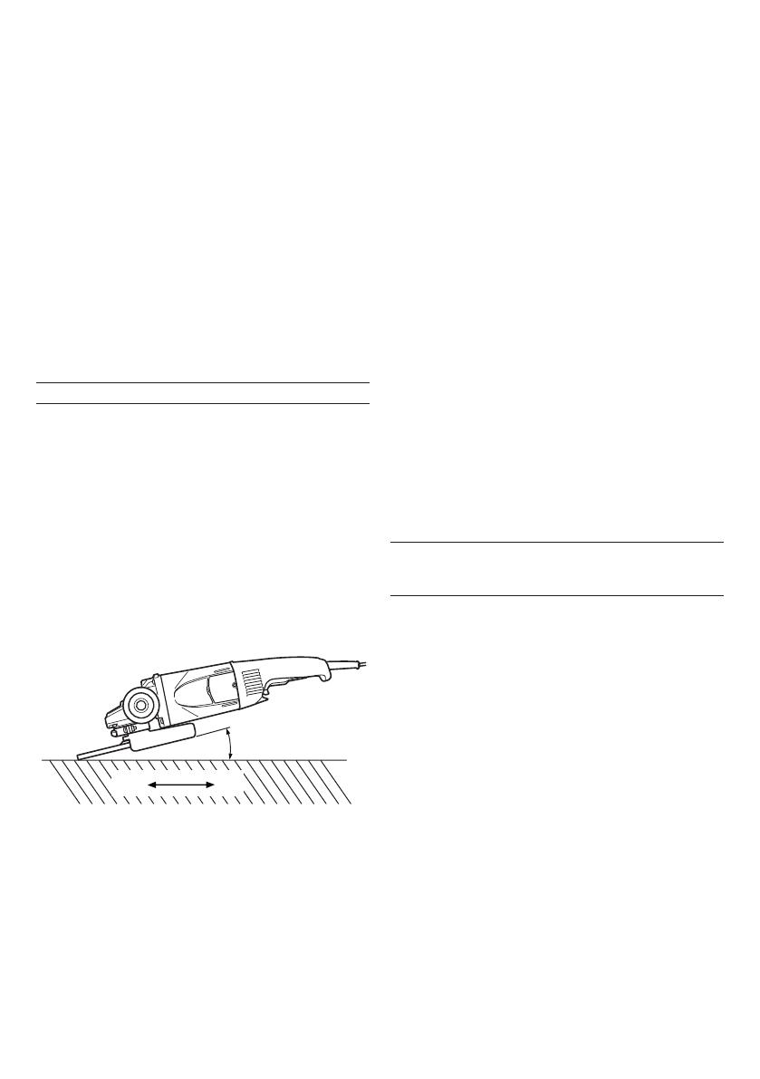
6. Always hold the body handle and side handle of the
power tool firmly. Otherwise the counterforce
produced may result in inaccurate and even
dangerous operation.
7. Do not use cutting-off wheels for side grinding.
8. Do not use of separate reducing bushings or adapters
to adapt large hole abrasive wheels.
9. The wheel continues to rotate after the tool is switched
off.
2
SPECIFICATIONS
*1 Be sure to check the nameplate on product as it is subject to change by areas.
*2 Weight: Only main body
*3 The starting current limiter produces the starting current to such an extent that a fuse (16A, slow-blow) is not
tripped.
STANDARD ACCESSORIES
(1) Wrench ........................................................................ 1
(2) Side handle ................................................................ 1
Depressed center wheels are not provided as standard
accessories.
Standard accessories are subject to change without
notice.
APPLICATIONS
Removal of casting fin and finishing of various types
of steel, bronze and aluminum materials and castings.
Grinding of welded sections or sections cut by means
of a cutting torch.
Grinding of synthetic resins, slate, brick, marble, etc.
Cutting of synthetic concrete, stone, brick, marble
and similar materials.
PRIOR TO OPERATION
1. Power source
Ensure that the power source to be utilized conforms
to the power requirements specified on the product
nameplate.
2. Power switch
Ensure that the power switch is in the OFF position. If
the plug is connected to a receptacle while the power
switch is in the ON position, the power tool will start
operating immediately, which could cause a serious
accident.
3. Extension cord
When the work area is removed from the power
source, use an extension cord of sufficient thickness
and rated capacity. The extension cord should be
kept as short as practicable.
4. Fitting and adjusting the wheel guard
The wheel guard is a protective device to prevent
injury should the depressed center wheel shatter
during operation. Ensure that the guard is properly
fitted and fastened before commencing grinding
operation.
[Adjusting the wheel guard, For G23SF2, G23U2 only]
By slightly loosening the setting screw, the wheel
guard can be turned and set at any desired angle for
maximum operational effectiveness.
Ensure that the setting screw is thoroughly tightened
after adjusting the wheel guard.
[Installing and adjusting the wheel guard, For G18SE3,
G18SG2, G23SE2, G23UB2 only]
Open the lever and insert the locating pin of wheel
guard, bringing it into line with the across flats of
packing ground.
Then, turn the wheel guard to a desired position (for
use).
Close the lever and fix it. If and when required, carry
out adjustments by tightening or loosening the screw.
If the lever does not move smoothly, apply some
lubricating oil to the sliding section between the set
piece and the lever.
Fasten the wheel guard at the position where the
across flats of the wheel guard positioning pin and
packing ground are aligned (the position where the
wheel guard is inserted), but do not use it.
Fig. 1
Locating pin
Lever
Screw
Set piece
Model G18SE3 G18SG2 G23SF2 G23U2 G23SE2 G23UB2
Voltage (by areas)*
1
(110V, 220V, 230V, 240V)
Input*
1
2300 W 2500 W 2000 W 2400 W, 2500 W
No-load speed 8500 min
-1
6600 min
-1
Outer dia. 180 mm 230 mm
Wheel Inner dia. 22 mm
Peripheral speed 80 m/s
Weight*
2
5.0 kg 4.3 kg 5.0 kg
Starting current limiter*
3
No No Yes No Yes
3
5. Ensure that the depressed center wheel to be utilized
is the correct type and free of cracks or surface defects.
Also ensure that the depressed center wheel is
properly mounted and the wheel nut is securely
tightened, refer to the section on Depressed Center
Wheel Assembly.
6. Conducting a trial run
Ensure that the abrasive products is correctly mounted
and tightened before use and run the tool at no-load
for 30 seconds in a safe position, stop immediately if
there is considerable vibration or if other defects are
detected.
If this condition occurs, check the machine to
determine the cause.
7. Confirm the spindle lock mechanism
Confirm that the spindle lock is disengaged by pushing
push button two or three times before switching the
power tool on (See Fig. 3).
8. Fixing the side handle
Screw the side handle into the gear cover.
PRACTICAL GRINDER APPLICATION
1. Pressure
To prolong the life of the machine and ensure a first
class finish, it is important that the machine should
not be overloaded by applying too much pressure. In
most applications, the weight of the machine alone is
sufficient for effective grinding. Too much pressure
will result in reduced rotational speed, inferior surface
finish, and overloading which could reduce the life of
the machine.
2. Grinding angle
Do not apply the entire surface of the depressed
center wheel to the material to be ground. As shown
in Fig. 2, the machine should be held at an angle of
15° 30° so that the external edge of the depressed
center wheel contacts the material at an optimum
angle.
Fig. 2
3. To prevent a new depressed center wheel from
digging into the workpiece, initial grinding should be
performed by drawing the grinder across the
workpiece toward the operator (Fig. 2 direction B).
Once the leading edge of the depressed center wheel
is properly abraded, grinding may be conducted in
either direction.
4. Switch operation
Switch ON: Push the locking button forward and
then press the switch lever.
* For continuous use, press the switch
lever. The switch lever is locked by
pushing the locking button forward
once again.
(*Subject to change depending on
area.)
Switch OFF: Press and release the switch lever.
5. Precautions immediately after finishing operation
After switching off the machine, do not put it down
until the depressed center wheel has come to a
complete stop. Apart from avoiding serious accidents,
this precaution will reduce the amount of dust and
swarf sucked into the machine.
CAUTION:
Check that the work piece is properly supported.
Ensure that ventilation openings are kept clear when
working in dusty conditions.
If it should become necessary to clear dust, first
disconnect the tool from the mains supply (use non-
metallic objects) and avoid damaging internal parts.
Ensure that sparks resulting from use do not create a
hazard e.g. do not hit persons, or ignite flammable
substances.
Always use protective safety glasses and hearing
protectors, use other personal protective equipment
such as gloves, apron and helmet when necessary.
Always use eye and ear protection.
Other personal protective equipment such as dust
mask, gloves, helmet and apron should be worn
when necessary.
If in doubt, wear the protective equipment.
When the machine is not use, the power source
should be disconnected.
ASSEMBLING AND DISASSEMBLING THE
DEPRESSED CENTER WHEEL AND OTHER
TOOLS
CAUTION:
Be sure to switch OFF and disconnect the attachment
plug from the receptacle to avoid a serious accident.
1. Assembling (Fig. 3)
(1) Turn the machine upside down so that the spindle is
facing upward.
(2) Mount the wheel washer onto the spindle.
(3) Fit the protruding part of the depressed center wheel
or cutting wheel or diamond wheel onto the wheel
washer.
(4) Screw the wheel nut onto the spindle.
(For diamond wheel assembling, use the wheel nut
with the convex side against the diamond wheel.)
(5) Insert the push button to prevent rotation of the
spindle, and tighten the wheel nut with the accessory
wrench, as shown in Fig. 3.
2. Disassembling
Follow the above procedures in reverse.
CAUTION:
Comfirm that the depressed center wheel is mounted
firmly.
Confirm that the push button is disengaged by
pushing push button two or three times before
switching the power tool on.
15 30°
AB
4
MAINTENANCE AND INSPECTION
1. Inspecting the depressed center wheel
Ensure that the depressed center wheel is free of
cracks and surface defects.
2. Inspecting the mounting screws
Regularly inspect all mounting screws and ensure
that they are properly tightened. Should any of the
screws be loose, retighten them immediately. Failure
to do so could result in serious hazard.
3. Inspecting the carbon brushes
For your continued safety and electrical shock
protection, carbon brush inspection and replacement
on this tool should ONLY be performed by a Hitachi
Authorized Service Center.
4. Replacing supply cord
If the supply cord of Tool is damaged, the Tool must
be returned to Hitachi Authorized Service Center for
the cord to be replaced.
5. Maintenance of the motor
The motor unit winding is the very “heart” of the
power tool. Exercise due care to ensure the winding
does not become damaged and/or wet with oil or
water.
6. Service parts list
A: Item No.
B: Code No.
C: No. Used
D: Remarks
Wheel
nut
Brush cover
Socket for
side
handle
Push button
(Spindle lock)
Switch
Lock button
Spindle
Side handle
Wheel
guard
Wheel
washer
Depressed
center
wheel
Wheel
nut
Wrench
Diamond
wheel
Across flats
Wheel
washer
Cutting
wheel
Wheel
nut
Wheel
washer
Fig. 3
CAUTION:
Repair, modification and inspection of Hitachi Power
Tools must be carried out by an Hitachi Authorized
Service Center.
This Parts List will be helpful if presented with the
tool to the Hitachi Authorized Service Center when
requesting repair or other maintenance.
In the operation and maintenance of power tools, the
safety regulations and standards prescribed in each
country must be observed.
MODIFICATIONS:
Hitachi Power Tools are constantly being improved
and modified to incorporate the latest technological
advancements.
Accordingly, some parts (i.e. code numbers and/or
design) may be changed without prior notice.
NOTE:
Due to HITACHI’s continuing program of research and
development, the specifications herein are subject to
change without prior notice.
5
G18SE3
ABC D
37 937-908Z 1
38 316-824 1 180MM A24R
39 937-909Z 1
40 320-218 1
41 306-890 1
42 320-241 1 7, 20
43 320-216 1
44 600-0VV 1 6000VVCMPS2L
45 321-536 1
46 321-535 1 45
47 ———— 1
48 320-232 2
49 305-812 8 D4×16
50 999-061 2
51 320-231 1
52 ———— 1
53 320-233 2
54 320-245 2
55 320-238 1
56 960-266 1
57 984-750 2 D4×16
58 320-230 1
59 981-373 2
60 958-049 1 D8.2
61 500-408Z 1
501 937-913Z 1
502 937-917Z 1
ABC D
1 315-636 2 M5×14
2 301-654 4 D5×35
3 306-888 1
4 320-219 1
5 320-217 1 3, 4, 17, 40,
41
6 320-226 1 M10
7 320-243 1
8 320-221 1
9 320-222 1
10 630-1DD 1 6301DDCMPS2L
11 994-208 1
12 320-220 1
13 1 360-594U 1 110V-120V
9, 10, 43, 44
13 2 360-594E 1 220V-230V
13 3 360-594F 1 240V
14 320-215 1
15 984-271 2 D5×75
16 1 340-546C 1 110V-120V
16 2 340-546E 1 220V-230V
16 3 340-546F 1 240V
17 937-033 1
18 321-542 1
19 939-542 1
20 320-242 1
21 949-236 2 M5×10
22 320-229 1
23 630-2DD 1 6302DDCMPS2L
24 990-852 1
25 320-234 1
26 320-228 1
27 320-227 1
28 994-192 4 M5×16
29 311-492 1
30 321-546 1
31 321-545 1
32 306-887 1 M8×22
33 949-457 1 M8
34 321-544 1
35 673-489 1
36 321-543 1 29-35
1
2
3
4
5
6
7
8
9
10
11
12
13
14
15
16
17
18
19
20
21
22
23
24
25
27
28
29
26
30
31
32
33
34
35
36
37
38
39
40
41
42
43
44
45
46
47
48
49
50
51
49
49
48
52
50
49
53
54
53
54
55
56
57
58
59
60
61
501 502
6
G18SG2
ABC D
38 316-824 1 180MM A24R
NZL
39 937-909Z 1
40 320-218 1
41 306-890 1
42 320-241 1 7, 20
43 320-216 1
44 600-0VV 1 6000VVCMPS2L
45 321-536 1
46 321-535 1 45
47 ———— 1
48 320-232 2
49 305-812 8 D4×16
50 1 999-061 1
50 2 999-089 1
51 320-231 1
52 ———— 1
53 320-233 2
54 320-245 2
55 1 320-238 1
55 2 320-239 1 ESP, AUT
56 960-266 1
57 984-750 2 D4×16
58 320-230 1
59 981-373 2
60 1 940-778 1 D10.7
60 2 958-049 1 D8.2
61 ———— 1
501 937-913Z 1
502 937-917Z 1 NZL
ABC D
1 315-636 2 M5×14
2 301-654 4 D5×35
3 306-888 1
4 320-219 1
5 320-217 1 3, 4, 17, 40, 41
6 320-226 1 M10
7 320-243 1
8 320-221 1
9 320-222 1
10 630-1DD 1 6301DDCMPS2L
11 994-208 1
12 320-220 1
13 360-594E 1 220V-230V
14 320-215 1
15 984-271 2 D5×75
16 340-546E 1 220V-230V
17 937-033 1
18 321-542 1
19 939-542 1
20 320-242 1
21 949-236 2 M5×10
22 320-229 1
23 630-2DD 1 6302DDCMPS2L
24 990-852 1
25 320-234 1
26 320-228 1
27 320-227 1
28 994-192 4 M5×16
29 311-492 1
30 321-546 1
31 321-545 1
32 306-887 1 M8×22
33 949-457 1 M8
34 321-544 1
35 673-489 1
36 321-543 1 29-35
37 1 937-907Z 1
37 2 937-908Z 1 NZL
7
G23SF2
ABC D
39 320-214 1 38"
40 ———— 1
41 320-232 2
42 305-812 2 D4×16
43 1 999-061 1
43 2 999-089 1
44 320-231 1
45 305-812 4 D4×16
46 305-812 2 D4×16
47 ———— 1
48 320-233 2
49 320-245 2
50 320-238 1
51 960-266 1
52 984-750 2 D4×16
53 320-230 1
54 981-373 2
55 958-049 1 D8.2
56 500-439Z 1
501 937-913Z 1
502 937-917Z 1
ABC D
1 315-636 2 M5×14
2 301-654 4 D5×35
3 306-888 1
4 320-219 1
5 320-217 1 3, 4, 33, 34"
6 320-226 1 M10
7 320-225 1
8 320-221 1
9 320-222 1
10 630-1DD 1
6301DDUCMPS2S
11 994-208 1
12 320-220 1
13 360-558E 1 220V-240V
14 320-215 1
15 961-501 2 D5×60
16 1 340-501E 1 220V-230V
16 2 340-501F 1 240V
17 937-981 1
18 939-542 1
19 320-224 1
20 949-236 2 M5×10
21 320-229 1
22 630-2DD 1
6302DDUCMPS2S
23 990-852 1
24 320-234 1
25 320-228 1
26 320-227 1
27 994-192 4 M5×16
28 306-887 1 M8×22
29 306-120 1 28"
30 937-908Z 1
31 316-825 1 230MM A24R
32 937-909Z 1 M14×2
33 320-218 1
34 306-890 1
35 320-223 1 7, 19"
36 320-216 1
37 600-0VV 1 6000VVCMPS2L
38 320-244 1
1
2
3
4
5
6
7
8
9
10
11
12
13
14
15
16
17
18
19
20
21
22
23
24
25
26
27
28
29
30
31
32
33
34
35
36
37
38
39
40
41
42
43
44
45
41
46
42
47
48
48
49
51
54
55
501
502
53
52
50
43
49
56
8
G23U2
ABC D
1 315-636 2 M5×14
2 301-654 4 D5×35
3 306-888 1
4 320-219 1
5 320-217 1 3, 4, 33, 34"
6 320-226 1 M10
7 320-225 1
8 320-221 1
9 320-222 1
10 630-1DD 1
6301DDUCMPS2S
11 994-208 1
12 320-220 1
13 360-558E 1 220V-240V
14 320-215 1
15 961-501 2 D5×60
16 1 340-501E 1 220V-230V
16 2 340-501F 1 240V
17 937-981 1
18 939-542 1
19 320-224 1
20 949-236 2 M5×10
21 320-229 1
22 630-2DD 1
6302DDUCMPS2S
23 990-852 1
24 320-234 1
25 320-228 1
26 320-227 1
27 994-192 4 M5×16
28 306-887 1 M8×22
29 306-120 1 28"
30 937-908Z 1
31 316-825 1 230MM A24R
32 937-909Z 1 M14×2
33 320-218 1
34 306-890 1
35 320-223 1 7, 19"
36 320-216 1
37 600-0VV 1 6000VVCMPS2L
38 320-244 1
39 320-214 1 38"
40 ———— 1
ABC D
41 320-232 2
42 305-812 2 D4×16
43 1 999-061 1
43 2 999-089 1
44 320-231 1
45 305-812 4 D4×16
46 305-812 2 D4×16
47 ———— 1
48 320-233 2
49 320-245 2
50 320-236 1
51 320-371 1
52 960-266 1
53 984-750 2 D4×16
54 320-230 1
55 981-373 2
56 958-049 1 D8.2
57 500-439Z 1
501 937-913Z 1
502 937-917Z 1
1
2
3
4
5
6
7
8
9
10
11
12
13
14
15
16
17
18
19
20
21
22
23
24
25
26
27
28
29
30
31
32
33
34
35
36
37
38
39
40
41
42
43
44
45
41
46
42
47
48
49
51
54
55
501
502
53
52
50
43
56
48
49
57
9
ABC D
1 315-636 2 M5×14
2 301-654 4 D5×35
3 306-888 1
4 320-219 1
5 320-217 1 3, 4, 17, 40,
41
6 320-226 1 M10
7 320-225 1
8 320-221 1
9 320-222 1
10 630-1DD 1 6301DDCMPS2L
11 994-208 1
12 320-220 1
13 1 360-594E 1 220V-230V
13 2 360-594F 1 240V
14 320-215 1
15 984-271 2 D5×75
16 1 340-546E 1 220V-230V
16 2 340-546F 1 240V
17 937-033 1
18 321-542 1
19 939-542 1
20 320-224 1
21 949-236 2 M5×10
22 320-229 1
23 630-2DD 1 6302DDCMPS2L
24 990-852 1
25 320-234 1
26 320-228 1
27 320-227 1
28 994-192 4 M5×16
29 311-492 1
30 321-546 1
31 321-545 1
32 306-887 1 M8×22
33 949-457 1 M8
34 321-544 1
35 673-489 1
36 321-547 1 29-35
37 937-908Z 1
38 316-825 1 230MM A24R
ABC D
39 937-909Z 1
40 320-218 1
41 306-890 1
42 320-223 1 7, 20
43 320-216 1
44 600-0VV 1 6000VVCMPS2L
45 321-536 1
46 321-535 1 45
47 ———— 1
48 320-232 2
49 305-812 8 D4×16
50 999-061 2
51 320-231 1
52 ———— 1
53 320-233 2
54 320-245 2
55 320-238 1
56 960-266 1
57 984-750 2 D4×16
58 320-230 1
59 981-373 2
60 958-049 1 D8.2
61 500-408Z 1
501 937-913Z 1
502 937-917Z 1
G23SE2
1
2
3
4
5
6
7
8
9
10
11
12
13
14
15
16
17
18
19
20
21
22
23
24
25
26
27
28
29
30
31
32
33
34
35
36
37
38
39
40
41
42
43
44
45
46
47
48
49
50
51
49
49
48
52
50
49
53
54
53
54
55
56
57
58
59
60
61
501
502
10
G23UB2
ABC D
1 315-636 2 M5×14
2 301-654 4 D5×35
3 306-888 1
4 320-219 1
5 320-217 1 3, 4, 17, 40,
41
6 320-226 1 M10
7 320-225 1
8 320-221 1
9 320-222 1
10 630-1DD 1 6301DDCMPS2L
11 994-208 1
12 320-220 1
13 1 360-594U 1 110V-120V
9, 10, 43, 44
13 2 360-594E 1 220V-230V
13 3 360-594F 1 240V
14 320-215 1
15 984-271 2 D5×75
16 1 340-546C 1 110V-120V
16 2 340-546E 1 220V-230V
16 3 340-546F 1 240V
17 937-033 1
18 321-542 1
19 939-542 1
20 320-224 1
21 949-236 2 M5×10
22 320-229 1
23 630-2DD 1 6302DDCMPS2L
24 990-852 1
25 320-234 1
26 320-228 1
27 320-227 1
28 994-192 4 M5×16
29 311-492 1
30 321-546 1
31 321-545 1
32 306-887 1 M8×22
33 949-457 1 M8
34 321-544 1
35 673-489 1
ABC D
36 321-547 1 29-35
37 937-908Z 1
38 316-825 1 230MM A24R
39 937-909Z 1
40 320-218 1
41 306-890 1
42 320-223 1 7, 20
43 320-216 1
44 600-0VV 1 6000VVCMPS2L
45 321-536 1
46 321-535 1 45
46 ———— 1
48 320-232 2
49 305-812 8 D4×16
50 999-061 2
51 320-231 1
52 ———— 1
53 320-233 2
54 320-245 2
55 320-236 1
56 320-371 1
57 960-266 1
58 984-750 2 D4×16
59 320-230 1
60 981-373 2
61 958-049 1 D8.2
62 500-408Z 1
501 937-913Z 1
502 937-917Z 1
1
2
3
4
5
6
7
8
9
10
11
12
13
14
15
16
17
18
19
20
21
22
23
24
25
26
27
28
29
30
31
32
33
34
35
36
37
38
39
40
41
42
43
44
45
46
47
48
49
50
51
52
53
54
55
56
57
58
59
60
61
53
501
502
48
49
49
49
50
54
62
403
Code No. C99122514
Printed in Malaysia
Hitachi Koki Co., Ltd.
  • Page 1 1
  • Page 2 2
  • Page 3 3
  • Page 4 4
  • Page 5 5
  • Page 6 6
  • Page 7 7
  • Page 8 8
  • Page 9 9
  • Page 10 10
  • Page 11 11
  • Page 12 12

Hitachi G 18MR User manual

Category
Power tools
Type
User manual

Ask a question and I''ll find the answer in the document

Finding information in a document is now easier with AI