Consumer Products
2006
LX
SERIES LAWN TRACTORS
LX SERIES LAWN TRACTORSLX
GT2000 SERIES GARDEN TRACTORS
DEMYSTIFICATION GUIDE
About this manual
We hope that you fi nd this manual a valuable addition to your service shop. If you
Manager or us directly at the following assress:
The Toro Company
Consumer service department
8111 Lyndale Avenue South
Bloomington, MN 55420-1196
The Toro company reserves the right to change product specifi cations or this
manual without notice.
Copyright© - All Rights Reserved
The Toro Company - 2006
Bloomington, MN 55420-1149 - U.S.
A
TABLE OF CONTENTS
D
emystifi cation G
lossary
1-1
Table of contents
. . . . . . . . . . . . . . . . . . . . . . . . . . . . . . . . . . . . . . . . . . . . . . . . . . . . . . . . .
1-1
Time Savers
. . . . . . . . . . . . . . . . . . . . . . . . . . . . . . . . . . . . . . . . . . . . . . . . . . . . . . . . . . . . .
2-1
Glossary
. . . . . . . . . . . . . . . . . . . . . . . . . . . . . . . . . . . . . . . . . . . . . . . . . . . . . . . . . . . . . . . .
3-1
LX420 / LX460
. . . . . . . . . . . . . . . . . . . . . . . . . . . . . . . . . . . . . . . . . . . . . . . . . . . . . . . . . . .
4-1
LX500 / GT2100 / GT2200 / GT2300
. . . . . . . . . . . . . . . . . . . . . . . . . . . . . . . . . . . . . . . . . .
5-1
CHAPTER PAGE
1-2
Demystifi cation
G
lossary
This page intentionally left blank
TIME SAVERS
D
emystifi cation G
lossary
2-1
Table of contents
Using this manual
. . . . . . . . . . . . . . . . . . . . . . . . . . . . . . . . . . . . . . . . . . . . . . . . . . . . . . . . .
2-2
Using a VOM
. . . . . . . . . . . . . . . . . . . . . . . . . . . . . . . . . . . . . . . . . . . . . . . . . . . . . . . . . . . .
2-7
Troubleshooting
. . . . . . . . . . . . . . . . . . . . . . . . . . . . . . . . . . . . . . . . . . . . . . . . . . . . . . . . . .
2-9
TIME
SAVERS
2-2
Demystifi cation
G
lossary
Using this Manual
GLOSSARY
Demysti
ction Glossary
ction Glossary
1-11
GLOSSARY
Solenoid, Starter
Location
The starter solenoid is located under the rear fender
assembly to the right of the battery (Figure 8).
Purpose
The solenoidʼs purpose is simply to connect the
battery to the starter motor when the ignition switch
is turned to “START”. The solenoid is used to protect
the ignition switch from the high current drawn by the
starter motor.
How it Works
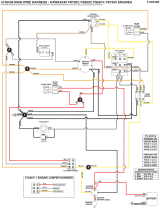
The solenoid has two primary parts. One is a coil of
wire wrapped around an iron core. Whenever 12 volts
is applied to the coil, it becomes a magnet. The other
part is a bar type switch (Figure 9). Because it has a
large contact area with the contact terminals it can
easily handle the high current loads required by the
starter motor.
When 12 volts is applied to the coil, it becomes an
electromagnet. This quickly pulls the bar toward
contacts and closes the switch. When power is
removed from the coil, the spring loaded bar returns
to its “normally open” position. The solenoid closes
and opens the switch very quickly. This minimizes the
“arcing” that can damage other types of switches.
The ignition switch is protected because only a small
amount of current is needed to activate the coil.
Testing
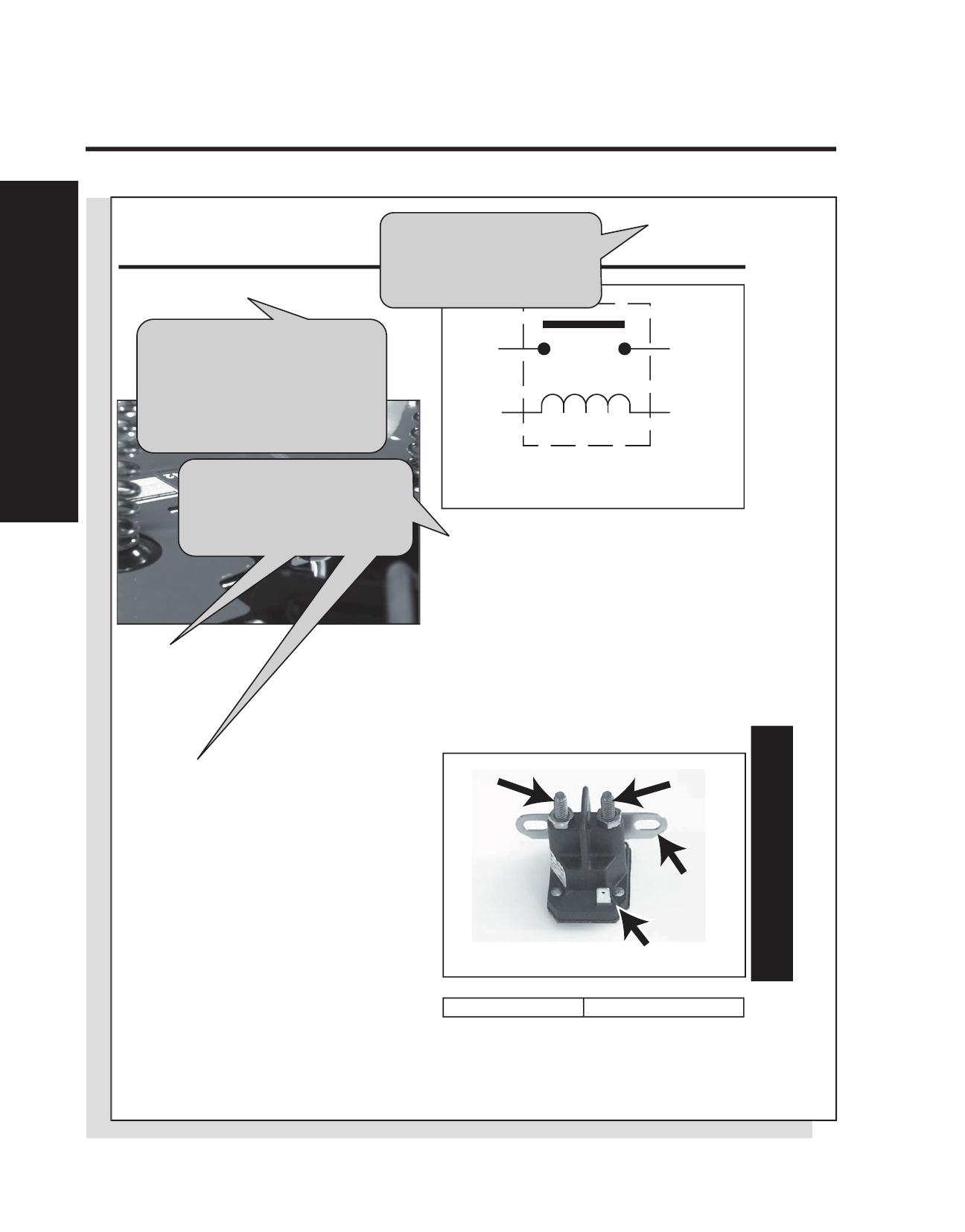
1. Disconnect the solenoid from the wiring harness.
2. With a multimeter (ohms setting), check to ensure
that terminals “c” and “d” are open (no continuity)
(Figure 10).
3. Apply +12 VDC to terminal “a” and ground mounting
tab “b”. Terminals “c” and “d” should now be closed
(continuity) (Figure 10).
4. You should be able to hear the solenoid switch
“click” when you make the connection.
(A) & (B) Coil Terminals (C) & (D) Contact Terminals
Solenoid
(not energized)
C
A
D
B
Figure 8
solloc
Figure 9
start sol
C
D
B
A
Figure 10
start sol
The components are listed
alphabetically by noun, followed
by any adjectives. If you have
trouble finding a component, use
the Table of Contents at the front
of the Glossary section.
The Glossary contains
information on virtually every
electrical part used on Toro
riding products.
These three sections should be
all you need to diagnose
problems on individual
components.
TIME SAVERS
D
emystifi cation G
lossary
2-3
Using this Manual
2006
LX420, LX460
Demysti
cation Guide
cation Guide
2-1
Information List
LX420 Information List (2006)
LX460 Information List (2006)
Wiring Diagram. . . . . . . . . . . . . . . . . . . . . . . . . . . . . . 3 - 2
Circuit Diagrams
Starter Motor Circuit . . . . . . . . . . . . . . . . . . . . . 3 - 4
Spark Circuits . . . . . . . . . . . . . . . . . . . . 3 - 5 - 3 - 12
Each product series has its own
section including:
- Info List
- Wiring Diagrams
- Circuit Diagrams
The "Info List" is the
first page of each
product section.
Each product section has its own
"Table of Contents" to keep things
simple.
Image helps you quickly
identify product sections.
TIME
SAVERS
2-4
Demystifi cation
G
lossary
Using this Manual
Wiring Diagram
LX420, LX460
2006
2-2
Demysti
cation Guide
cation Guide
Wiring Diagram
BU
W
W
R
R
R
R
R
Y
Y
Y
Y Y
Y/BK
Y/BK
Y/W
GN
GN
GN
GN
GN
GND
GN
OR
OR OR/BK OR/BK
R/W
R/W R/W
R/W
HEADLIGHT HARNESS
IGNITION SWITCH
OFF G M A1
RUN 1 B A1 AND L A2
RUN 2 B A1
START B S A1
G
L M S B A1
A2
BRAKE +
BRAKE
PTO
PTO +
N/C
GND
+ 12V
SYSTEMS INDICATOR MONITOR / HOUR METER
BRAKE SWITCH
BRAKE SWITCH IS SHOWN
WITH BRAKE APPLIED
PARK SWITCH
PARK SWITCH IS SHOWN
PARK BRAKE ON
OR/BK
OR/BK
OR
OR/W OR/W
Each product section includes
the original wiring diagram.
The wiring diagrams
are drawn on a two
page spread to make
them easier to read.
The arrows show the
conection point.
TIME SAVERS
D
emystifi cation G
lossary
2-5
Using this Manual
Wiring Diagram
2006
LX420, LX460
Demysti
cation Guide
cation Guide
2-3
Wiring Diagram
IGNITION
MODULE
SPARK PLUG
AC
AC
BN
BU
GY
W
WW
PUR
R
RR
RR
R R
R
R
PK
BK
Y
Y
Y
Y/BK
Y/BK
Y/BK
Y/BK
Y/BK
Y/BK
Y/WY/W
Y/W YELLOW WHITE
Y
T
GN
GN
GN
OR
OR/BK OR/W
BROWN
BLUE
GRAY
WHITE
PURPLE
RED
PINK
BLACK
YELLOW
TAN
GREEN
ORANGE
WIRE COLOR CODES
R/WR/W
R/W
YELLOW BLACK
RED WHITE
R/W
REG
START
MAG
B+
+
-
STARTER
SOLENOID
FUSE
A1 POWER PB BYPASS
PARK SW
MAGNETO
A2 POWER
GROUND
RMC MODULE
REV SW
PTO SWITCH
PTO SWITCH IS SHOWN
WITH PTO OFF
20A
AFTERFIRE
SOLENOID
SEAT SWITCH
SEAT SWITCH IS SHOWN
WITH OPERATOR PRESENT
REVERSE SWITCH
REVERSE SWITCH IS
SHOWN IN FORWARD
OR/W
OR/BK
OR/W
ORNGE BLACK
ORNGE WHITE
R/BK
R/BK RED BLACK
The wiring diagram
closely represents the
wiring harness and is
very useful in
diagnosing short
circuits.
TIME
SAVERS
2-6
Demystifi cation
G
lossary
Using this Manual
BN
BU
GY
W
PUR
R
PK
BK
Y
Y/BK
Y/W YELLOW WHITE
T
GN
OR
BROWN
BLUE
GRAY
WHITE
PURPLE
RED
PINK
BLACK
YELLOW
TAN
GREEN
ORANGE
WIRE COLOR CODES
R/W
YELLOW BLACK
RED WHITE
OR/BK
OR/W
ORNGE BLACK
ORNGE WHITE
R/BK RED BLACK
Demysti
cation Guide
cation Guide
3-5
Circuits
2006
LX500,GT2100
GT2200, GT2300
Starter Motor Circuit
(ignition switch in “start”)
Spark Circuit
(ignition switch in “start”)
Fuel Solenoid
(Energized)
Headlight Harness
(Headlights on)
Battery
Fuse
(20 Amp)
A1
B
S
Ignition Switch
(In Start)
Starter Motor
(Energized)
Starter Solenoid
(Energized)
Brake Switch
(Brake Applied)
PTO Switch
(PTO Off)
R R
R
R
R
R R R
Rw
Or Or/bk Or/w
Or/w
Bu
Gn
IGNITION
MODULES
SPARK PLUG SPARK PLUG
Dashed lines do not carry current
GN
GN
Y
Y
Y/W
G
M
Ignition Switch
(In Start)
Brake Switch
(Brake Applied)
Seat Switch
(Operator On)
Each circuit is shown
individually. Components
not essential for circuit
function are not shown.
Additional information is
called out beneath the
title in parenthesis.
Each circuit diagram
page has a color code
legend.
Solid lines indicate
wires that carry current.
Components with
internal circuitry are
enclosed with a dashed
line.
Each component is
named and additional
information is supplied
below in parentheses.
Circuits are drawn such that
current usually flows from left
to right (the same way you read).
Circuit diagrams make
troubleshooting easy
and fun because each
circuit is drawn individually.
They make troubleshooting
open circuits a snap.
Wire colors are called
out at each component
(where you're most
likely to use them!)
Each component (i.e.
switches, relays,
solenoids) are drawn in
the position necessary to
make the circuit function.
Dashed lines represent wires that
are important to the circuit, but do
not carry current.
TIME SAVERS
D
emystifi cation G
lossary
2-7
Using a VOM
Checking Voltage
Checking Voltage
Checking Resistance
1
1
2
2
What about checking current?
3
TIME
SAVERS
2-8
Demystifi cation
G
lossary
Using a VOM
TIME SAVERS
D
emystifi cation G
lossary
2-9
Troubleshooting
Fuel Solenoid
(Energized)
IGNITION
MODULES
SPARK PLUGSPARK PLUG
Dashed lines do not carry current
GN
GN
Y
Y
Y/W
R
R
R
R
Y/BK
GN
R Rw
Rw
R
Bu
Bu
Gn
R
GN
Headlight Harness
(Headlights on)
2
G
B A1
M
Ignition Switch
(In Normal)
Brake Switch
(Brake Off)
Seat Switch
(Operator On)
PTO Switch
(PTO On)
A1 Power
E-PTO
Ground
Seat Switch
RMC Module
Rev Sw
Reverse Switch
(In Forward)
R/BK
Battery
Fuse
(20 Amp)
5
1
3
4
Relay
(Not Energized)
W/BKW/BK
Y/BK
Y/BK
PTO
Clutch
(Engaged)
W
BU/W
1. Test for voltage Across the PTO
clutch coil by connecting the Pos.
lead to the blue/white wire and the
Neg. lead to the white wire.
Bat. voltage - check clutch coil
resistance.
No voltage step-2.
TIP: DON'T
DISCONNECT
ANY WIRES!
When checking
for voltage you
need only touch
the terminals.
(disconnect
components
when checking
resistance.)
TIP: BE LAZY! If you have trouble
getting to a component, skip it, and go
to the next point (You can always go
back if your next reading is 0 volts.)
3. Move Neg. lead to yellow/black
wire at relay plug.
Bat. voltage - check reverse & seat
switch.
No voltage step-4.
2. Move Neg. lead to
good chassis ground.
Bat. voltage - step-3.
No voltage step-4.
4. Move Pos. lead to red wire
at PTO plug.
Bat. voltage - check PTO switch.
No voltage - check ignition switch.
Sample Problem: GT2100 electric clutch will not engage
Sample Problem: LX420 will not crank
Fuel Solenoid
(Energized)
Headlight Harness
(Headlights on)
Battery
Fuse
(20 Amp)
A1
B
S
Ignition Switch
(In Start)
Starter Motor
(Energized)
Starter Solenoid
(Energized)
Brake Switch
(Brake Applied)
PTO Switch
(PTO Off)
R R
R
R
R
R R R
Rw
Or Or/bk Or/w
Or/w
Bu
Gn
Quick check:
does solenoid “click” when
key is turned to start?
If yes, you can eliminate circuit
from fuse to solenoid coil.
TIP: Use test points to
divide circuit in half.
1.Test point “a” for voltage.
Voltage is 12V. Problem is right
half of circuit.
Proceed to point “b”.
2. Test point “b” voltage reads 0V.
Problem is between “a” and “b”.
Proceed to point “c”.
3. Test point “c” Voltage is 12V.
Problem is between “c” and “b”.
Proceed to Point “d”.
4. Test point “d”. Voltage is 0V.
You disconnect the PTO switch
and find it to be defective.
TIME
SAVERS
2-10
Demystifi cation
G
lossary
Troubleshooting
Sample Problem: This GT tractor won’t turn over. The customer parked
it in the garage and turned it off. When he tried to start it a week later, he
heard one click. After that, nothing would happen when he turned the key.
We know it’s a short because we found the 20 amp fuse blown.
BU
PUR
PUR
R
R
R
R
R
R
R
Y
Y
Y Y/W
GN
GN
GN
GN
GN
GN
GN
GN
GN
GN
OR
OR
R/W
R/W
R/W
HEADLIGHT HARNESS
2
IGNITION SWITCH
OFF G M A1
RUN 1 B A1 AND L A2
RUN 2 B A1
START B S A1
GL M S B A1 A2
BRAKE +
BRAKE
PTO
PTO +
N/C
GND
+ 12V
SYSTEMS INDICATOR MONITOR / HOUR METER
PTO
CLUTCH
5
1
3
4
Relay
BRAKE SWITCH
BRAKE SWITCH IS SHOWN
WITH BRAKE APPLIED
OR/BK
OR/BK
OR/BK
OR
W/BK
W/BK
W
W
OR/BK
OR/W
OR/W
BU/W
BU/W
Y/BK
Y/BK
Step 1. Interview the customer.
Any information we get will help
isolate the problem.
Highlight the suspect area on a
copy of the wiring diagram.
Eliminate the green wires as
possibilities because they’re
supposed to go to ground.
TIME SAVERS
D
emystifi cation G
lossary
2-11
Troubleshooting
IGNITION
MODULES
SPARK PLUG
SPARK PLUG
AC
AC
PUR
PUR
R
R
R
R
R
R R
R
R
Y
Y
Y
Y
Y/W
Y/W
GN
GN
R/W
R/W
R/W
BN
BU
GY
W
PUR
R
PK
BK
Y
Y/BK
Y/W YELLOW WHITE
T
GN
OR
BROWN
BLUE
GRAY
WHITE
PURPLE
RED
PINK
BLACK
YELLOW
TAN
GREEN
ORANGE
WIRE COLOR CODES
R/W
YELLOW BLACK
RED WHITE
REG
START
MAG
B+
+
-
STARTER
SOLENOID
FUSE
A1 POWER
SEAT SW
E-PTO
A2 POWER
GROUND
RMC MODULE
REV SW
PTO SWITCH
PTO SWITCH IS SHOWN
WITH PTO OFF
20A
AFTERFIRE
SOLENOID
SEAT SWITCH
SEAT SWITCH IS SHOWN
WITH OPERATOR PRESENT
REVERSE SWITCH
REVERSE SWITCH IS
SHOWN IN FORWARD
OR/BK
OR/BKOR/BK
W/BK
W/BK
OR/W
OR/W
OR/W
BU/W
BU/W
Y/BK
R/BK
Y/BK
Y/BK
OR/BK
OR/W
ORANGE BLACK
ORANGE WHITE
R/BK RED BLACK
Step 2. Isolate the suspect area.
Notice what we did to the wiring
diagram below.
If the short was between the battery
and the 20 amp fuse, we would have
melted these wires.
TIME
SAVERS
2-12
Demystifi cation
G
lossary
Troubleshooting
BU
PUR
PUR
R
R
R
R
R
R
R
Y
Y
Y Y/W
GN
GN
GN
GN
GN
GN
GN
GN
GN
GN
OR
OR
R/W
R/W
R/W
HEADLIGHT HARNESS
2
IGNITION SWITCH
OFF G M A1
RUN 1 B A1 AND L A2
RUN 2 B A1
START B S A1
GL M S B A1 A2
BRAKE +
BRAKE
PTO
PTO +
N/C
GND
+ 12V
SYSTEMS INDICATOR MONITOR / HOUR METER
PTO
CLUTCH
5
1
3
4
Relay
BRAKE SWITCH
BRAKE SWITCH IS SHOWN
WITH BRAKE APPLIED
OR/BK
OR/BK
OR/BK
OR
W/BK
W/BK
W
W
OR/BK
OR/W
OR/W
BU/W
BU/W
Y/BK
Y/BK
Step 3. Break the suspect area
down into “mini-circuits”. Do this
by unplugging unswitched circuits
and by opening all Switches.
Separate the connector
for the lights since this is
an unswitched circuit.
Open the suspect part of
the brake switch by
releasing the brake.
Open the ignition switch
by turning it “off”.
TIME SAVERS
D
emystifi cation G
lossary
2-13
Troubleshooting
IGNITION
MODULES
SPARK PLUG
SPARK PLUG
AC
AC
PUR
PUR
R
R
R
R
R
R R
R
R
Y
Y
Y
Y
Y/W
Y/W
GN
GN
R/W
R/W
R/W
BN
BU
GY
W
PUR
R
PK
BK
Y
Y/BK
Y/W YELLOW WHITE
T
GN
OR
BROWN
BLUE
GRAY
WHITE
PURPLE
RED
PINK
BLACK
YELLOW
TAN
GREEN
ORANGE
WIRE COLOR CODES
R/W
YELLOW BLACK
RED WHITE
REG
START
MAG
B+
+
-
STARTER
SOLENOID
FUSE
A1 POWER
SEAT SW
E-PTO
A2 POWER
GROUND
RMC MODULE
REV SW
PTO SWITCH
PTO SWITCH IS SHOWN
WITH PTO OFF
20A
AFTERFIRE
SOLENOID
SEAT SWITCH
SEAT SWITCH IS SHOWN
WITH OPERATOR PRESENT
REVERSE SWITCH
REVERSE SWITCH IS
SHOWN IN FORWARD
OR/BK
OR/BKOR/BK
W/BK
W/BK
OR/W
OR/W
OR/W
BU/W
BU/W
Y/BK
R/BK
Y/BK
Y/BK
OR/BK
OR/W
ORANGE BLACK
ORANGE WHITE
R/BK RED BLACK
Remove the connector
from the PTO switch to
open both suspect circuits.
TIME
SAVERS
2-14
Demystifi cation
G
lossary
Troubleshooting
BU
PUR
PUR
R
R
R
R
R
R
R
Y
Y
Y Y/W
GN
GN
GN
GN
GN
GN
GN
GN
GN
GN
OR
OR
R/W
R/W
R/W
HEADLIGHT HARNESS
2
IGNITION SWITCH
OFF G M A1
RUN 1 B A1 AND L A2
RUN 2 B A1
START B S A1
GL M S B A1 A2
BRAKE +
BRAKE
PTO
PTO +
N/C
GND
+ 12V
SYSTEMS INDICATOR MONITOR / HOUR METER
PTO
CLUTCH
5
1
3
4
Relay
BRAKE SWITCH
BRAKE SWITCH IS SHOWN
WITH BRAKE APPLIED
OR/BK
OR/BK
OR/BK
OR
W/BK
W/BK
W
W
OR/BK
OR/W
OR/W
BU/W
BU/W
Y/BK
Y/BK
Step 4. Power up the mini-circuits
one at a time, beginning with the
one closest to the battery.
Close the suspect part of the brake
switch by applying the brake.
When the ignition switch is turned
to “normal”, the 20 amp fuse
doesn’t blow. This means the red
wires are OK.
Next, turn the ignition switch to
“start”. This powers up the orange,
orange/black, and orange/white
wires. The fuse doesn’t blow so
these wires are OK.
TIME SAVERS
D
emystifi cation G
lossary
2-15
Troubleshooting
IGNITION
MODULES
SPARK PLUG
SPARK PLUG
AC
AC
PUR
PUR
R
R
R
R
R
R R
R
R
Y
Y
Y
Y
Y/W
Y/W
GN
GN
R/W
R/W
R/W
BN
BU
GY
W
PUR
R
PK
BK
Y
Y/BK
Y/W YELLOW WHITE
T
GN
OR
BROWN
BLUE
GRAY
WHITE
PURPLE
RED
PINK
BLACK
YELLOW
TAN
GREEN
ORANGE
WIRE COLOR CODES
R/W
YELLOW BLACK
RED WHITE
REG
START
MAG
B+
+
-
STARTER
SOLENOID
FUSE
A1 POWER
SEAT SW
E-PTO
A2 POWER
GROUND
RMC MODULE
REV SW
PTO SWITCH
PTO SWITCH IS SHOWN
WITH PTO OFF
20A
AFTERFIRE
SOLENOID
SEAT SWITCH
SEAT SWITCH IS SHOWN
WITH OPERATOR PRESENT
REVERSE SWITCH
REVERSE SWITCH IS
SHOWN IN FORWARD
OR/BK
OR/BKOR/BK
W/BK
W/BK
OR/W
OR/W
OR/W
BU/W
BU/W
Y/BK
R/BK
Y/BK
Y/BK
OR/BK
OR/W
ORANGE BLACK
ORANGE WHITE
R/BK RED BLACK
Install a new 20 amp fuse.
This “powers up” the red/white
wire to the ignition switch. The
fuse doesn’t blow, so this wire
is OK.
Install the connector to the PTO
switch, leave the switch in the
“off” position.
TIME
SAVERS
2-16
Demystifi cation
G
lossary
Troubleshooting
BU
PUR
PUR
R
R
R
R
R
R
R
Y
Y
Y Y/W
GN
GN
GN
GN
GN
GN
GN
GN
GN
GN
OR
OR
R/W
R/W
R/W
HEADLIGHT HARNESS
2
IGNITION SWITCH
OFF G M A1
RUN 1 B A1 AND L A2
RUN 2 B A1
START B S A1
GL M S B A1 A2
BRAKE +
BRAKE
PTO
PTO +
N/C
GND
+ 12V
SYSTEMS INDICATOR MONITOR / HOUR METER
PTO
CLUTCH
5
1
3
4
Relay
BRAKE SWITCH
BRAKE SWITCH IS SHOWN
WITH BRAKE APPLIED
OR/BK
OR/BK
OR/BK
OR
W/BK
W/BK
W
W
OR/BK
OR/W
OR/W
BU/W
BU/W
Y/BK
Y/BK
Separate the plug at the electric
clutch and check the blue/white
wire for continuity to ground. We
find there is continuity.
Tracing the blue/white wire we find
that it is pinched in the chassis.
Problem solved!
Reconnect the light circuit,
the fuse doesn’t blow so
this circuit is OK.
Leave the ignition switch
in the “normal” position.
  • Page 1 1
  • Page 2 2
  • Page 3 3
  • Page 4 4
  • Page 5 5
  • Page 6 6
  • Page 7 7
  • Page 8 8
  • Page 9 9
  • Page 10 10
  • Page 11 11
  • Page 12 12
  • Page 13 13
  • Page 14 14
  • Page 15 15
  • Page 16 16
  • Page 17 17
  • Page 18 18
  • Page 19 19
  • Page 20 20
  • Page 21 21
  • Page 22 22
  • Page 23 23
  • Page 24 24
  • Page 25 25
  • Page 26 26
  • Page 27 27
  • Page 28 28
  • Page 29 29
  • Page 30 30
  • Page 31 31
  • Page 32 32
  • Page 33 33
  • Page 34 34
  • Page 35 35
  • Page 36 36
  • Page 37 37
  • Page 38 38
  • Page 39 39
  • Page 40 40
  • Page 41 41
  • Page 42 42
  • Page 43 43
  • Page 44 44
  • Page 45 45
  • Page 46 46
  • Page 47 47
  • Page 48 48
  • Page 49 49
  • Page 50 50
  • Page 51 51
  • Page 52 52
  • Page 53 53
  • Page 54 54
  • Page 55 55
  • Page 56 56
  • Page 57 57
  • Page 58 58
  • Page 59 59
  • Page 60 60
  • Page 61 61
  • Page 62 62
  • Page 63 63
  • Page 64 64
  • Page 65 65

Ask a question and I''ll find the answer in the document

Finding information in a document is now easier with AI