Altronix AL400ULB User manual

Category
Power adapters & inverters
Type
User manual

Altronix AL400ULB is a power supply/charger that converts a 28VAC input into a Class 2 Rated power-limited 12VDC or 24VDC output. It features a built-in charger for sealed lead acid or gel type batteries, automatic switch over to stand-by battery when AC fails, and visual indicators for AC input and DC output. It also has short circuit and thermal overload protection.

Altronix AL400ULB is a power supply/charger that converts a 28VAC input into a Class 2 Rated power-limited 12VDC or 24VDC output. It features a built-in charger for sealed lead acid or gel type batteries, automatic switch over to stand-by battery when AC fails, and visual indicators for AC input and DC output. It also has short circuit and thermal overload protection.

Power Supply Output Specifications:
Output
VDC
Switch Position Max. Stand-by
Load DC
Max. Alarm
Load DC
Stand-by Battery
12VDC SW 1, 2 ON,
SW3, 4 OFF
4.0 amp
200mA
4.0 amp
4.0 amp
24V/40AH
12V/12AH
24VDC SW 1, 2 OFF,
SW3, 4 ON
3.0 amp
200mA
3.0 amp
3.0 amp
24VDC
24V/12AH
Stand-by Specifications:
Output 4 hr. of Stand-by &
5 Minutes of Alarm
24 hr. of Stand-by &
5 Minutes of Alarm
60 hr. of Stand-by &
5 Minutes of Alarm
12VDC / 40AH Battery
Stand-by = 4.0 amp
Alarm = 4.0 amp
Stand-by = 1.0 amp
Alarm = 4.0 amp
Stand-by = 300mA
Alarm = 4.0 amp
24VDC / 12AH Battery --------
Stand-by = 200mA
Alarm = 3.0 amp
--------
24VDC / 40AH Battery
Stand-by = 3.0 amp
Alarm = 3.0 amp
Stand-by = 1.0 amp
Alarm = 3.0 amp
Stand-by = 300mA
Alarm = 3.0 amp
Installation Instructions:
The AL400ULB should be installed in accordance with article 760 of The National Electrical Code or NFPA 72 as well
as all applicable Local Codes.
1. Mount AL400ULB in the desired location/enclosure.
2. Connect 28VAC / 175VA transformer to the terminals marked [AC, AC], (Fig. 1).
Use 18 AWG or larger for all power connections (Battery, DC output). Use 22 AWG to 18 AWG for the
power-limited circuits (AC Fail/Low Battery reporting).
Keep power-limited wiring separate from non power-limited wiring (115VAC / 60Hz Input, Battery Wires).
Minimum 0.25” spacing must be provided.
3. Set the AL400ULB to the desired DC output voltage by setting the switches to the appropriate positions
(Power Supply Output Specifications Table).
4. Connect devices to be powered to the terminals marked [+ DC – ] (Fig. 1).
AL400ULB
UL Recognized Power Supply/Charger
(AL400ULB Board)
Output Dip Switches
Overview:
The AL400ULB is a power-limited supply/charger that converts a 28VAC / 100VA input into a Class 2 Rated
power-limited 12VDC or 24VDC output (see specifications).
Specifications:
Agency Listings:
• ULRecognizedcomponentforAccessControl
System Units (UL 294), Standard for Power
Supplies for Use with Burglar-Alarm Systems (UL 603),
Standard for Safety for Fire Protective Signaling
Systems (UL 1481).
Input:
• Input28VAC/100VA.
Output:
• Class2Ratedpower-limitedoutput.
• 12VDCor24VDCselectableoutput.
• 4ampcontinuoussupplycurrent@12VDC.
• 3ampcontinuoussupplycurrent@24VDC.
• Filteredandelectronicallyregulatedoutput.
Battery Backup:
• Built-inchargerforsealedleadacidorgeltypebatteries.
• Maximumchargecurrent600mA.
• Automaticswitchovertostand-bybattery
when AC fails.
Visual Indicators:
• ACinputandDCoutputLEDindicators.
Supervision:
• ACfailsupervision(form“C”contacts).
• Lowbatterysupervision(form“C”contacts).
Additional Features:
• Shortcircuitandthermaloverloadprotection.
Board Dimensions (W x L x H approximate):
4.1”x7.1”x1.75”(104.14mmx180.34mmx44.45mm)
5. Measure output voltage before connecting devices.
This helps avoiding potential damage.
6. For Access Control applications batteries are optional.
When batteries are not used, a loss of AC will result in the
loss of output voltage. When the use of stand-by batteries
is desired, they must be lead acid or gel type.
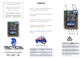
Connect battery to the terminals [– BAT +] (Fig. 1) as
marked on the unit (battery leads included).
Use two (2) 12VDC batteries connected in series for
24VDC operation.
7. Connect supervisory trouble reporting devices to the
outputsmarked[LOWBAT,ACFAIL] supervisory relays
marked [NC, NO, C ] (Fig. 1).
Use 22 AWG to 18 AWG for AC Fail & Low Battery reporting.
Maintenance:
Unit should be tested at least once a year for the proper operation as follows:
Output Voltage Test: Under normal load conditions the DC output voltage should be checked for proper voltage level
(Power Supply Output Specifications Table).
Battery Test: Under normal load conditions check that the battery is fully charged, check specified voltage both
at the battery terminal and at the board terminals marked [- BAT +] to ensure that there is no break in the battery
connection wires.
Note: Maximumchargingcurrentunderdischargesis1.25amp.
Note:Expectedbatterylifeis5years;however,itisrecommendedchangingbatteriesin4yearsorlessifneeded.
LED Diagnostics:
LED ON OFF
AC (Green) Normal operation No AC input
BAT (Red) Battery connected Battery disconnected
DC (Red) Normal operation No DC output
Terminal Identification:
Terminal Legend Function/Description
AC, AC Low voltage (28VAC) transformer connections.
+ DC – 12VDC@4ampor24VDC@3ampcontinuouspower-limitedoutput.
AC Fail
NC, NO, C
IndicateslossofACpower,e.g.connecttoaudibledeviceoralarmpanel.Relaynormallyener-
gizedwhenACpowerispresent.Contactrating1amp@30VDC.
Bat Fail
NC, C, NO
Indicateslowbatterycondition,e.g.connecttoalarmpanel.Relaynormallyenergizedwhen
DCpowerispresent.Contactrating1amp@30VDC.Aremovedbatteryisreportedwithin5
minutes. Battery reconnection is reported within 1 minute.
-- BAT + Stand-bybatteryconnections.Maximumchargecurrent1.2amp.
+ DC --
AC FAIL NC NO C NC C NO LOW BAT
-- BAT +
DC
AC
1 2 3 4
ON
AC AC
24V - SW1, 2 OFF
SW3, 4 ON
12V - SW1, 2 ON
SW3, 4 OFF
Fig. 1
Altronixisnotresponsibleforanytypographicalerrors.
14058thStreet,Brooklyn,NewYork11220USA,718-567-8181,fax:718-567-9056
website:www.altronix.com,e-mail:[email protected],LifetimeWarranty,MadeinU.S.A.
IIAL400ULB-Rev.061400 H15M
MEMBER
  • Page 1 1
  • Page 2 2

Altronix AL400ULB User manual

Category
Power adapters & inverters
Type
User manual

Altronix AL400ULB is a power supply/charger that converts a 28VAC input into a Class 2 Rated power-limited 12VDC or 24VDC output. It features a built-in charger for sealed lead acid or gel type batteries, automatic switch over to stand-by battery when AC fails, and visual indicators for AC input and DC output. It also has short circuit and thermal overload protection.

Ask a question and I''ll find the answer in the document

Finding information in a document is now easier with AI