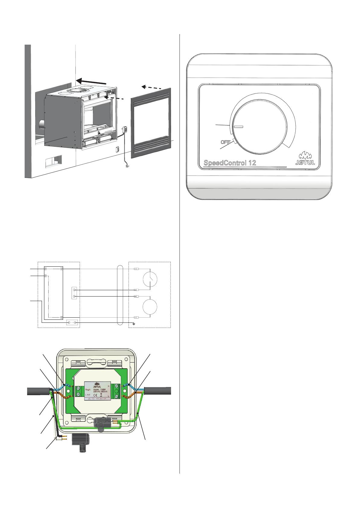
Jotul C 620 Fan User manual

Type
User manual

Jotul C 620 Fan enhances room comfort by effectively warming the room through increased air circulation in the convection chamber. It features a thermostat that automatically starts the fan at a selected speed when the burn chamber generates heat and stops it when the chamber cools down. The fan operates at two speeds, with an approximate airflow of 140 m3/h at the lowest setting and 180 m3/h at the highest. Installation requires securing the fan to the front bracket, connecting the fan and control box, and mounting the control box in a suitable location.

Jotul C 620 Fan enhances room comfort by effectively warming the room through increased air circulation in the convection chamber. It features a thermostat that automatically starts the fan at a selected speed when the burn chamber generates heat and stops it when the chamber cools down. The fan operates at two speeds, with an approximate airflow of 140 m3/h at the lowest setting and 180 m3/h at the highest. Installation requires securing the fan to the front bracket, connecting the fan and control box, and mounting the control box in a suitable location.

Fan Jøtul C 620
UK - Installation and Operating instructions 3
FR - Manuel d`installation et d`utilisation 5
IT - Installazione e lstruzioni per l`uso 7
ES - Manual de instruccones 9
Fan Jøtul C620
Manual Version P02
Manualene må oppbevares under hele produktets levetid. The manuals which are enclosed with the product must be kept throughout the product’s
entire service life. Les manuels fournis avec le produit doivent être conservés pendant toute la durée de vie du produit. Los manuales suministrados
con este producto deben guardarse durante todo el ciclo de vida del producto. I manuali inclusi con il prodotto vanno conservati per l’intera durata di
vita del prodotto. Das im Lieferumfang des Produkts enthaltene Begleitmaterial ist über die gesamte Nutzungsdauer aufzubewahren. De bij de haard
meegeleverde handleidingen moeten gedurende de volledige gebruiksduur van de haard bewaard blijven.
2
3
Jøtul C 620 has a fan solution that increases air
circulation in the convection chamber, thereby
effectively warming the room and providing
enhanced comfort.
Installation
Check that all the parts are included in the package:
Fan
Installation manual
Bag of screws and cable ties
Control box
Cable and plug
Fig 1
A
1. Unscrew the 4 screws securing the front bracket (A) with
a 5 mm Allen key.
2. Tilt out the front bracket (A).
Fig 2
1
1. Use pliers to remove the cable lid.
Fig 3
1. Unscrew the screws from the front bracket, and use them
to secure the fan to the front bracket.
Fig 4
2
3
1
1. Tilt in the front bracket and fan.
2. Reattach the 4 screws (see g.1) securing the front bracket
with a 5 mm Allen key.
3. Flip the thermostat inwards.
Fig 5
1
3
2
1. Thread the cable with the female connector through the
slot made in g.2, and connect it to the fan.
2. Bend the connection inwards, so that the connector will t
inside the frame (see the installation manual that comes
with the cassette).
3. Use a cable tie to secure the cable to the bracket on the
bottom of the fan cover (make sure there is enough cable
for the connector to t).
ENGLISH
4
Fig 6
1. Install the cassette into the surround and mount the frame,
as shown in in the installation manual that comes with the
cassette. There must be room for the cable to t without
being damaged on the outside of the cassette. NB: The
frame must be installed, as it protects the electrical
parts of the fan.
2. Install the control box (Fig. 8) in a suitable location,
following the wiring diagram in g. 7.
Fig 7a
Motor
Thermostat
Connector
Control box
(180 - 230VAC)
Fan
PE
L
N
Reg N.
L out 1
3
2
4
Brown
White
Black
Blue
Yellow/green
Fig 7b
1. Connect the wires in the control box according to g.7a+b.
NB: Installation must be carried out by a quali ed
electrician in conformance with local regulations.
The control box can now be connected to an electrical source.
Fig 8
A
B
A: The fan is o
B: The fan starts at the selected speed when the burn
chamber starts to generate heat. When the burn
chamber has cooled down again, the fan stops
automatically.
Lowest speed approx. 140 m
3/h
Highest speed approx. 180 m3/h
Setpoint
Start: 50oC
Stop: 35oC
The fan will start once the burn chamber reaches 50oC (ap-
prox. 45 minutes after lighting the re), and stop automatically
when the temperature drops below 35oC.
Fuse: 500 mA (not replaceable)
250 V
Power consumption: 16 W
Safety precautions
The installation can only be taken into use after it has been
checked by a quali ed inspector.
This appliance can be used by children aged from 8 years and
above and persons with reduced physical, sensory or mental
capabilities or lack of experience and knowledge if they have
been given supervision or instruction concerning use of the
appliance in a safe way and understand the hazards involved
Children shall not play with the appliance
Cleaning and user maintenance shall not be made by
children without supervision
ENGLISH
Blue Blue
Brown Brown
Green/Yellow
Green/Yellow
White
Black
5
Le poêle Jøtul C 620 possède un ventilateur qui
augmente la circulation de l’air dans la cham-
bre de convection, réchau ant ainsi e cace-
ment la pièce et o rant un confort accru.
Installation
Véri ez que toutes les pièces sont incluses dans le lot :
Ventilateur
Manuel d`installation
Sachet de vis et serre-câbles
Boîtier de commande
Câble et prise
Fig 1
A
1. Desserrez les 4 vis qui xent le support avant (A) avec une
clé six pans de 5 mm.
2. Inclinez le support avant vers l’extérieur (A).
Fig 2
1
1. Utilisez une pince pour retirer le couvercle du câble.
Fig 3
1. Desserrez les vis du support avant et utilisez-les pour xer
le ventilateur au support avant.
Fig 4
2
3
1
1. Inclinez le support avant et le ventilateur vers l’intérieur.
2. Resserrez les 4 vis (voir g.1) xant le support avant avec
une clé six pans de 5 mm.
3. Retournez le thermostat vers l’intérieur.
Fig 5
1
3
2
1. Faites passer le câble avec le connecteur femelle dans la
fente, voir g. 2, et connectez-le au ventilateur.
2. Pliez la connexion vers l’intérieur pour que le connecteur
s’insère dans le cadre (voir le manuel d’installation fourni
avec la cassette).
3. Utilisez des attaches de câble pour xer le câble au
support dans le fond du capot du ventilateur (veillez
à ce qu’il y ait su samment de câble pour adapter le
connecteur)
FRANÇAIS
6
Fig 6
1. Installez la cassette dans l’encadrement et montez le
cadre, comme indiqué dans le manuel d’installation
fourni. Il doit y avoir de la place pour que le câble passe
sans être endommagé à l’extérieur de la cassette. Il est
important que le cadre soit monté car cela protège les
composants électriques du ventilateur.
2. Installez le boîtier de commande (Fig. 8) dans un endroit
approprié, en suivant le schéma de câblage de la g. 7.
Fig 7a
Moteur
Thermostat
Connecteur
Boîtier de commande
(180 - 230VAC)
Ventilateur
PE
L
N
Reg N.
L dehors 1
3
2
4
Marron
Blanc
Noir
Bleu
Jaune/Verte
Fig 7b
1. Branchez les ls dans le boîtier de commande
conformément à la g. 7a + b. Remarque : l’installation
doit être e ectuée par un électricien quali é en
conformité avec les réglementations locales.
Le ventilateur peut maintenant être connecté à l’électricité.
Fig 8
A
B
A: Le ventilateur est éteint
B: Le ventilateur démarre à la vitesse sélectionnée lor
sque le foyer commence à générer de la chaleur.
Quand le foyer s’est à nouveau refroidi, le ventila
teur s’arrête automatiquement.
Vitesse faible environ 140 m
3/h
Vitesse élevée environ 180 m3/h
Point de consigne
Start: 50oC
Stop: 35oC
Le ventilateur démarre dès que la chambre de combustion at-
teint 50oC (environ 45 minutes après l’allumage du feu) et
s’arrête automatiquement lorsque la température descend au-
dessous de 35oC.
Fusible: 500 mA (non remplaçable)
250 V
Consommation énergétique: 16 W
Précautions de sécurité
L’installation ne doit pas être utilisée avant d’avoir été inspectée
et approuvée.
Cet appareil peut être utilisé par des enfants âgés de
8 ans et plus et des personnes ayant des capacités
physiques, sensorielles ou mentales réduites ou un manque
d’expérience et de connaissances s’ils ont reçu une
supervision ou des instructions concernant l’utilisation de
l’appareil de manière sûre et comprennent les dangers induit.
Les enfants ne doivent pas jouer avec l’appareil
Le nettoyage et l’entretien par l’utilisateur ne doivent pas être
e ectués par des enfants sans surveillance
FRANÇAIS
Bleu Bleu
Marron Marron
Vert/Jaune
Vert/Jaune
Blanc
Noir
7
Jøtul C 620 presenta una soluzione con ventola
in grado di aumentare la circolazione dell’aria
nella camera di convezione, riscaldando e -
cacemente la stanza e fornendo maggiore com-
fort.
Installazione
Controllare che la confezione contenga tutti i componenti:
Ventilatore
Manuale di installazione
Sacchetto delle viti e fascette per cavi
Pannello di comando
Cavo e presa
Fig 1
A
1. Svitare le 4 viti che ssano la sta a anteriore (A) con una
chiave Allen da 5 mm.
2. Inclinare verso l’esterno la sta a anteriore (A).
Fig 2
1
1. Utilizzare le pinze per rimuovere il coperchio cavi.
Fig 3
1. Svitare le viti dalla sta a anteriore e utilizzarle per ssare
la ventola alla sta a anteriore.
Fig 4
2
3
1
1. Inclinare verso l’interno la sta a anteriore e la ventola.
2. Reinserire le 4 viti (vedere gura 1) che ssano la sta a
anteriore con una chiave Allen da 5 mm.
3. Ruotare il termostato verso l’interno.
Fig 5
1
3
2
1. Inserire il cavo con il connettore femmina attraverso il foro
praticato nella gura 2 e collegarlo alla ventola.
2. Piegare il collegamento verso l’interno, in modo che
il connettore trovi posto all’interno del telaio (vedere il
manuale di installazione fornito con la cassetta).
3. Fissare il cavo alla sta a sul fondo della copertura della
ventola (assicurarsi che vi sia cavo su ciente perché il
connettore si inserisca).
ITALIANO
8
Fig 6
1. Montare la cassetta nel rivestimento e montare il telaio
come illustrato nel manuale di installazione fornito con
la cassetta. Lo spazio per il cavo deve essere su ciente
perché non riporti danni all’esterno della cassetta. È
importante che il telaio sia montato perché protegge i
componenti elettrici della ventola.
2. Montare il pannello di comando (Fig. 8) in un luogo adatto,
attenendosi allo schema elettrico della gura 7.
Fig 7a
Motore
Termostato
Connettore
Panello du comando
(180 - 230VAC)
Ventilatore
PE
L
N
Reg N.
L fuori 1
3
2
4
Marrone
Bianco
Nero
Blu
Giallo/Verde
Fig 7b
1. Collegare i li del pannello di comando come mostrato
nelle gure 7a+b. Nota: l’installazione deve essere
e ettuata da un elettricista quali cato in conformità con le
normative locali.
È ora possibile collegare l’unità della ventola all’elettricità
Fig 8
A
B
A: La ventola è spenta
B: La ventola si avvia alla velocità selezionata quando
la camera di combustione inizia a generare calore.
Quando la camera di combustione si è nuovamente
ra reddata, la ventola si arresta automaticamente.
Velocità inferiore circa 140 m
3/h
Velocità superiore circa 180 m3/h
Setpoint
Start: 50oC
Stop: 35oC
La ventola si attiverà quando la camera di combustione rag-
giunge 50oC (circa 45 minuti dopo l’accensione del fuoco) e
si arresterà automaticamente quando la temperatura scende
sotto ai 35oC.
Fusibile: 500 mA (non sostituibile)
250 V
Consumo energetico: 16 W
Misure di sicurezza
L’installazione può essere e ettuata solo dopo un’accurata
ispezione da parte di personale quali cato.
Questo apparecchio può essere utilizzato per proteggere
bambini oltre gli 8 anni di età e adulti con ridotte capacità
siche o mentali o mancanza di esperienza e conoscenza
sotto la supervisione e istruendoli sull’apparecchio per un
utilizzo sicuro lasciando che gli stessi comprendano i pericoli
coinvolti
Ii bambini non devono giocare con l’apparecchio
La pulizia e la manutenzione dell’utente NON devono essere
eseguite da bambini senza supervisione
ITALIANO
Blu Blu
Marrone Marrone
Verde/Giallo
Verde/Giallo
Bianco
Nero
9
El casete Jøtul C 620 se puede equipar con
una solución de ventilador que aumenta la cir-
culación del aire en la cámara de convección,
calentando con e cacia la habitación y mejo-
rando el confort.
Instalaciòn
Veri que que todas las partes estén incluidas en el
paquete:
El ventilador
Manual de instruccones
Bolsa de tornillos y bridas
Caja de control
Cable y enchufe
Fig 1
A
1. Desatornille los 4 tornillos que sujetan el soporte frontal
(A) con una llave Allen de 5 mm.
2. Saque el soporte frontal (A).
Fig 2
1
1. Use unos alicates para quitar la tapa del cable.
Fig 3
1. Desatornille los tornillos del soporte frontal y úselos para
asegurar el ventilador al soporte frontal.
Fig 4
2
3
1
1. Reinstale el soporte frontal y el ventilador.
2. Vuelva a colocar los 4 tornillos (vea la gura 1) que
aseguran el soporte frontal con una llave Allen de 5 mm.
3. Voltee el termostato hacia adentro.
Fig 5
1
3
2
1. Pase el cable con el conector hembra a través de la ranura
hecha en la gura 2. Conecte el enchufe al ventilador.
2. Doble la conexión hacia adentro, de modo que el conector
encaje dentro del marco (consulte el manual de instalación
que viene con el casete).
3. Sujete el cable al enganche que hay en la base de la tapa
del ventilador (asegúrese de pasar cable su ciente para
efectuar la conexión)
ESPOL
10
Fig 6
1. Instale el casete en el marco y monte el marco, como
se muestra en el manual de instalación que viene con el
casete. Debe haber espacio para que el cable encaje sin
dañarse en el exterior del casete. Es importante que el
marco esté montado porque protege los componentes
eléctricos del ventilador.
2. Instale la caja de control (Fig. 8) en una ubicación
adecuada, siguiendo el diagrama de cableado de la g. 7.
Fig 7a
Motor
Termostato
Conector
Caja de control
(180 - 230VAC)
Ventilador
PE
L
N
Reg N.
L fuera 1
3
2
4
Marrón
Blanco
Negro
Azul
Amarillo/Verde
Fig 7b
1. Conecte los cables en la caja de control de acuerdo con
la gura 7a + b.
Nota: el ventilador debe instalarlo un electricista cuali cado
con arreglo a la normativa local.
Enchufe el ventilador a la red eléctrica y pruébelo.
Fig 8
A
B
A: El ventilador permanece apagado
B: El ventilador arranca a la velocidad seleccionada cu
ando la cámara de combustión empieza a generar
calor y se para cuando la cámara de combustión se
enfría.
Velocidad baja aprox. 140 m
3/h
Velocidad alta aprox. 180 m3/h
Punto jo
Iniciar: 50oC
Deténgase: 35oC
El ventilador arrancará una vez que la cámara de combustión
alcance los 50oC (aproximadamente 45 minutos después de
encender el fuego) y se detendrá automáticamente cuando la
temperatura baje a menos de 35oC.
Fusionar: 500 mA (no reemplazable)
250 V
Power consumption: 16 W
Precauciones de seguridad
La instalación sólo puede utilizarse una vez que haya sido
revisada por un inspector cuali cado.
Este aparato lo pueden usar niños de más de 8 años de edad
y personas con capacidades físicas, sensoriales o mentales
reducidas, o carentes de experiencia y conocimiento siempre
y cuando hayan recibido supervisión o instrucciones respecto
al uso del aparato de forma segura y comprendan los riesgos
Los niños no deben jugar con el aparato
La limpieza y el mantenimiento de usuario no los deben
llevar a cabo niños sin supervisión
ESPOL
Azul Azul
Marrón Marrón
Verde/Amarillo
Verde/Amarillo
Blanco
Negro
11
Jøtul pursues a policy of constant product development. Products supplied may therefore
di er in speci cation, colour and type of accessories from those illustrated and described
in the manual.
Jøtul vise sans cesse à améliorer ses produits. C’est pourquoi, il se réserve le droit de
modi er les speci cations, couleurs et équipements sans avis prélable.
Quality
Jøtul AS has a quality system that conforms to NS-EN ISO 9001 for product development,
manufacturing, and distribution of stoves and replaces. This policy gives our customers
quality and safety piece of mind as a result of Jøtul’s vast experience dating back to when
the company rst started in 1853.
Qualité
Le système de contrôle de la qualité de Jøtul AS est conforme à la norme NS-EN ISO 9001
relative à la conception, à la fabrication et à la distribution de poêles, foyers et inserts. Cette
politique nous permet d’o rir à nos clients une qualité et une sécurité reposant sur la vaste
expérience accumulée par Jøtul depuis sa création en 1853.
Jøtul AS,
P.o. box 1411
N-1602 Fredrikstad,
Norway
www.jotul.com
Cat.no. 10055288-P02
Jøtul AS, Feb. 2022
  • Page 1 1
  • Page 2 2
  • Page 3 3
  • Page 4 4
  • Page 5 5
  • Page 6 6
  • Page 7 7
  • Page 8 8
  • Page 9 9
  • Page 10 10
  • Page 11 11
  • Page 12 12

Jotul C 620 Fan User manual

Type
User manual

Jotul C 620 Fan enhances room comfort by effectively warming the room through increased air circulation in the convection chamber. It features a thermostat that automatically starts the fan at a selected speed when the burn chamber generates heat and stops it when the chamber cools down. The fan operates at two speeds, with an approximate airflow of 140 m3/h at the lowest setting and 180 m3/h at the highest. Installation requires securing the fan to the front bracket, connecting the fan and control box, and mounting the control box in a suitable location.

Ask a question and I''ll find the answer in the document

Finding information in a document is now easier with AI