Drolet ESCAPE 1500-I Owner's manual
- Category
- Wood stove
- Type
- Owner's manual
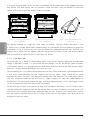
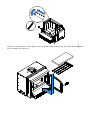
Drolet ESCAPE 1500-I is an efficient and clean-burning wood insert with a maximum heat output of 65,000 BTU/h, capable of heating up to 1,800 square feet. It features a simple, glass door with a cast iron frame, providing a clear view of the fire, and a built-in blower to circulate warm air efficiently. The EPA-certified wood insert meets strict emission standards, ensuring a more environmentally friendly heating solution. It also accommodates logs up to 16 inches in length, making it convenient to use.
Drolet ESCAPE 1500-I is an efficient and clean-burning wood insert with a maximum heat output of 65,000 BTU/h, capable of heating up to 1,800 square feet. It features a simple, glass door with a cast iron frame, providing a clear view of the fire, and a built-in blower to circulate warm air efficiently. The EPA-certified wood insert meets strict emission standards, ensuring a more environmentally friendly heating solution. It also accommodates logs up to 16 inches in length, making it convenient to use.


-
 1
1
-
 2
2
-
 3
3
-
 4
4
-
 5
5
-
 6
6
-
 7
7
-
 8
8
-
 9
9
-
 10
10
-
 11
11
-
 12
12
-
 13
13
-
 14
14
-
 15
15
-
 16
16
-
 17
17
-
 18
18
-
 19
19
-
 20
20
-
 21
21
-
 22
22
-
 23
23
-
 24
24
-
 25
25
-
 26
26
-
 27
27
-
 28
28
-
 29
29
-
 30
30
-
 31
31
-
 32
32
-
 33
33
-
 34
34
-
 35
35
-
 36
36


Drolet ESCAPE 1500-I Owner's manual
- Category
- Wood stove
- Type
- Owner's manual
Drolet ESCAPE 1500-I is an efficient and clean-burning wood insert with a maximum heat output of 65,000 BTU/h, capable of heating up to 1,800 square feet. It features a simple, glass door with a cast iron frame, providing a clear view of the fire, and a built-in blower to circulate warm air efficiently. The EPA-certified wood insert meets strict emission standards, ensuring a more environmentally friendly heating solution. It also accommodates logs up to 16 inches in length, making it convenient to use.
Ask a question and I''ll find the answer in the document
Finding information in a document is now easier with AI
Related papers
-
 Drolet ESCAPE 1500-I WOOD INSERT TRIO Owner's manual
-
Drolet DB03125 Owner's manual
-
 Drolet DB03122K Owner's manual
-
-
-
 Drolet Escape 1800 Insert Owner's manual
-
Drolet ESCAPE 1500 WOOD STOVE Owner's manual
-
Drolet ESCAPE 2100 WOOD STOVE Owner's manual
-
 Drolet CAPE TOWN 1800 CAST IRON WOOD STOVE Owner's manual
-
Drolet HT-3000 WOOD STOVE Owner's manual


Other documents
-
Osburn OB01705 Owner's manual
-
Enerzone EB00057 Owner's manual
-
Century CB00027 Owner's manual
-
-
-
-
-
-
Empire SF00613 Gateway 2300 Stove Archway 2300 Insert User manual
-