SpinCore DRX-4 Owner's manual

Type
Owner's manual

SpinCore DRX-4 is a versatile TTL line driver that offers exceptional signal integrity and high-speed data transmission capabilities. With four input channels and eight output lines, it reliably converts TTL input signals into robust TTL-level outputs, ensuring compatibility with various digital devices. Its ability to drive 50Ω loads effortlessly makes it suitable for a wide range of applications, including digital circuit testing, signal conditioning, and data acquisition systems.

SpinCore DRX-4 is a versatile TTL line driver that offers exceptional signal integrity and high-speed data transmission capabilities. With four input channels and eight output lines, it reliably converts TTL input signals into robust TTL-level outputs, ensuring compatibility with various digital devices. Its ability to drive 50Ω loads effortlessly makes it suitable for a wide range of applications, including digital circuit testing, signal conditioning, and data acquisition systems.

SpinCore TTL Line Driver
Model DRX-4
Owner's Manual
SpinCore Technologies, Inc.
www.spincore.com
http://www.spincore.com
SpinCore TTL Line Driver
Congratulations and thank you for choosing a design from SpinCore
Technologies, Inc.
We appreciate your business!
At SpinCore, we aim to fully support the needs of our customers. If you
are in need of assistance, please contact us and we will strive to
provide the necessary support.
© 2022 SpinCore Technologies, Inc. All rights reserved.
SpinCore Technologies, Inc. reserves the right to make changes to the product(s) or information herein without notice.
SpinCore TTL Line Driver and the SpinCore Technologies, Inc. logos are trademarks of SpinCore Technologies, Inc. All other trademarks
are the property of their respective owners.
SpinCore Technologies, Inc. makes every effort to verify the correct operation of the equipment. This equipment version is not intended
for use in a system in which the failure of a SpinCore device will threaten the safety of equipment or person(s).
2022/01/19
2
http://www.spincore.com
SpinCore TTL Line Driver
Table of Contents
I. Introduction .................................................................................................. 4
Product Overview ........................................................................................................... 4
Driver Architecture ......................................................................................................... 4
Design Overview ........................................................................................................ 4
Specifications .................................................................................................................. 4
II. Connecting to the SpinCore TLL Line Driver ........................................... 6
Connector Information ................................................................................................... 6
Connecting to the Device ............................................................................................... 6
Available Models ............................................................................................................. 7
Contact Information ........................................................................................ 8
Document Information .................................................................................... 8
2022/01/19
3
http://www.spincore.com
SpinCore TTL Line Driver
I. Introduction
Product Overview
The SpinCore TTL Line Driver is a USB powered device equipped with four input channels and 8 output
lines. Each of the output lines are capable of producing TTL levels over a 50 Ω load. To allow for a greater
range of applications, four of the 8 output lines have been inverted. All input channels and output lines are
accessible via BNC connectors. The SpinCore TTL Line Driver is available with a full 2U rack-mount
enclosure (model DRX-4E). Another option for the SpinCore TTL Line Driver is a 2U rack-mount front panel
only (model DRX-4F). The third and final model is without an enclosure (model DRX-4B).
Driver Architecture
Design Overview
The SpinCore TTL Line Driver utilizes a NAND gate (Philips 74F3037N) to drive the input signal to TTL
level outputs over a 50 Ω load. The drive capability of the Philips 74F3037N allows 67 mA source and 160 mA
sink. Typical rise and fall times of the Philips 74F3037N are 2.5 ns, with typical propagation delays of 2.0 ns.
*If you require better performance please contact SpinCore for inquiries on pricing.
Specifications
Four BNC input channels with 200 Ω internal termination. TTL levels required.
Four BNC non-inverted digital outputs. TTL levels assured over 50 Ω.
Four BNC inverted digital outputs. TTL levels assured over 50 Ω.
67 mA output drive capability for high state.
160 mA output drive capability for low state.
2022/01/19
4
Figure 1: Above is a schematic of a single channel on the SpinCore TTL Line Driver. An input TTL signal
is internally terminated over 200 Ω and driven through two NAND gates to create a non-inverted signal.
Additionally, a inverted signal is also created by driving the input signal through one NAND gate.
Input Signal Non-inverted Output Signal
Inverted Output Signal
200 Ω Termination 67 mA sourcing current
160 mA sinking current
http://www.spincore.com
SpinCore TTL Line Driver
The physical dimensions of the Line Driver are given below. The full enclosure weighs 1.66 kg.
Product Length Width Height
Board/PCB(cm) 31.2 4.6 N/A
Enclosure(cm) 48.3 5.2 8.8
Enclosure Without Front
Panel(cm)
42.7 5.1 8.2
Table 1: TTL Dimensions
A PBESR-PRO-500-PCI board was used for the images below showing the voltage levels without (Figure
2) and with (Figure 3) the TTL Line Driver. The transmission line was terminated with a 50 ohm resistor.
2022/01/19
5
Figure 2: A 400 ms period, 50% duty cycle pulses
from a PBESR-PRO-500-PCI that was terminated with
a 50 ohm resistor.
Figure 3: A 400 ms period, 50% duty cycle pulses
from the TTL Line Driver which had the incoming
signal from the PBESR-PRO-500-PCI board. The
transmission line was terminated with a 50 ohm
resistor.
http://www.spincore.com
SpinCore TTL Line Driver
II. Connecting to the SpinCore TLL Line Driver
Connector Information
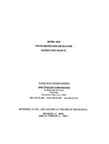
The device has a total of 12 BNC connectors and one USB Type B Connector. Starting from the left
edge of the device is the USB connection. The first four BNC connectors next to the USB connection are used
as inputs from other TTL devices. The middle four BNC connectors are the inverted output lines, and the last
four BNC connectors are the non-inverted output lines. Each of the four input channels has a corresponding
inverted and non-inverted output line which can be identified below by the numbers in the figure. Figure 4
provides a representation of the connector locations.
Connecting to the Device
The SpinCore TTL Line Driver board is a USB powered device. The device does not require the
installation of drivers or for the host computer to be turned off before being plugged in. Simply connect the
USB Type B cable to the board and host computer to power on the board.
Connecting the SpinCore TTL Line driver to other devices is very quick and simple. Once the board has
been powered on, connect the output of your device to one of the four input BNC connectors of the SpinCore
TTL Line Driver using a standard 50 Ω BNC cable.
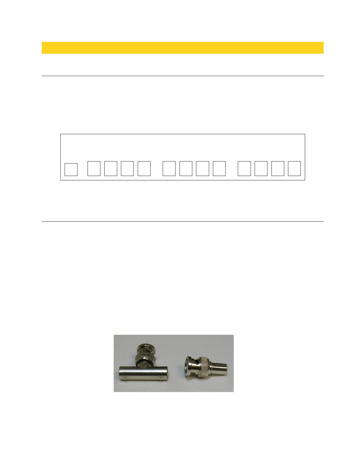
If using a high-input-impedance oscilloscope to evaluate the performance of the SpinCore TTL Line
Driver, place a resistor that matches the characteristic impedance of the transmission line in parallel with the
coaxial transmission line at the oscilloscope input. (e.g., a 50 Ω resistor with a 50 Ω transmission line, see
Figures 5 and 6). When using an oscilloscope with an adjustable bandwidth, set the bandwidth to as large as
possible. These settings are crucial to yield accurate readouts on the oscilloscope.
2022/01/19
6
Figure 4: Connector Locations
Figure 5: BNC T-Adapter (left) and 50 Ω BNC resistor (right)
USB Inputs Inverted Outputs Non-Inverted Outputs
1234 123 4 21 3 4
http://www.spincore.com
SpinCore TTL Line Driver
Available Models
The SpinCore TTL Line Driver is available in three models which are listed below. Ordering information
can be found at this link.
SpinCore TTL Line Driver DRX-4B – Equipped with four input channels and 8 output lines, the
SpinCore TTL Line Driver delivers enough current driving capabilities to work with 50 Ω loads. This
model is the bare board version of the SpinCore TTL Line Driver.
SpinCore TTL Line Driver DRX-4E – The SpinCore TTL Line Driver is placed in a standard 2U rack-
mount enclosure that protects the board from outside damage. The enclosure is equipped with two
metal handles for mobility and stability. This model is equipped with four input channels and 8 output
lines.
SpinCore TTL Line Driver DRX-4F – The SpinCore TTL Line Driver is connected to the front panel
of a standard 2U rack-mount enclosure. Please note that the entire SpinCore TTL Driver is not fully
enclosed in this model. The front panel has two metal handles for mobility and stability.
2022/01/19
7
Figure 6: BNC T-Adapter on the oscilloscope with coaxial transmission line connected on the left
and BNC 50 Ω resistor connected on the right to terminate the line.
http://www.spincore.com
SpinCore TTL Line Driver
Contact Information
SpinCore Technologies, Inc.
4631 NW 53rd Avenue, SUITE 103
Gainesville, FL 32653
USA
Telephone (USA): 352-271-7383
Website: http://www.spincore.com
Web Contact Form: http://spincore.com/contact.shtml
Document Information
Revision history available at SpinCore.
2022/01/19
8
  • Page 1 1
  • Page 2 2
  • Page 3 3
  • Page 4 4
  • Page 5 5
  • Page 6 6
  • Page 7 7
  • Page 8 8

SpinCore DRX-4 Owner's manual

Type
Owner's manual

SpinCore DRX-4 is a versatile TTL line driver that offers exceptional signal integrity and high-speed data transmission capabilities. With four input channels and eight output lines, it reliably converts TTL input signals into robust TTL-level outputs, ensuring compatibility with various digital devices. Its ability to drive 50Ω loads effortlessly makes it suitable for a wide range of applications, including digital circuit testing, signal conditioning, and data acquisition systems.

Ask a question and I''ll find the answer in the document

Finding information in a document is now easier with AI