Page is loading ...

Home » SQUARE D » SQUARE D 9422CMP50 Disconnect Mechanism Circuit Breaker Cable Operated
Instruction Manual
9422CMP50 Disconnect Mechanism Circuit
Breaker Cable Operated
Instruction Manual
Retain for future use.
Contents
1 Introduction
2 Kit Contents
3 Cable Operating Mechanisms
4 Installation
5 Mounting the Mechanism to the
Panel
6 Adjustment
7 Cable Operating Mechanisms
8 Documents / Resources
8.1 References
9 Related Posts
Introduction
The Class 9422 Type CMP cable mechanism for right-hand operation is for use with Square D™ PowerPacT™ M
and P circuit breakers and Class 9422 Type AP1, AP2, AP9, or AP10 operating handles. Table 1 lists the kit
contents. Table 2 on page 6 lists the device Types and corresponding cable lengths.
FIG. 1 : Operating Mechanism
SQUARE D 9422CMP50 Disconnect Mechanism Circuit
Breaker Cable Operated Instruction Manual
Manuals+ — User Manuals Simplified.

Table 1
B Bail arm
C Bail arm screw
EMechanical stop
F Right adjustment screw
G Left adjustment screw
H Push-to-trip button
J Cable nuts
K Forward increases on travel
L Rearward increases reset travel
M Flange mechanism coupler
Kit Contents

Item Art. Description Part No.
1 Operating mechanism assembly —
24 mechanism mounting screws, 1/4-20 x % i
n. Torque: 60-72 lb-in (6.8-8.1 Nrn) S31004-579-64
34 insulated circuit breaker mounting screws,
10-32 x 4-1/2″ supplied with breaker
4 Liner 30002-032-03
Cable Operating Mechanisms
DANGER
HAZARD OF ELECTRIC SHOCK, EXPLOSION, OR ARC FLASH
Disconnect all power before working on equipment.
Maintain electrical clearances between the cable and live electrical parts.
Verify by measurement that all power is disconnected.
Failure to follow these instructions will result in death or serious injury.
CAUTION
SPRING LOADED MOVING PARTS
Keep hands free of the mechanism during device operation.
Failure to follow these instructions can result in injury.
Installation
Refer to Figure 1 and Table 1 on page 1 when installing and adjusting the device; Figure 3 and Table 2 on page 5
for panel mounting; and Table 1 for torque values, unless otherwise noted.
The minimum cable bend radius is 5 in.
(127 mm), for a diameter of 10 in. (254 mm). To prevent multiple bends in the cable, do not loop or tie the cable to
the enclosure frame. Maintain electrical clearances between the cable and live electrical parts.
NOTE: Do not mount the operating mechanism to the panel at this time. That procedure is described on page 3.
However, ensure that the cable length is adequate to mount both the operating mechanism and the handle in the
proper locations.
1. With the mechanism bail arm (B) in the On position, remove the bail arm by removing the four screws (C).
2. Slide the liner (4) into the mechanism, aligning it with the mounting holes.
3. With the circuit breaker toggle and the operating mechanism in the On position, slide the circuit breaker into the
operating mechanism, aligning it with the four mounting holes.
NOTE: Visi-Trip™ Handles are not compatible with Equipment Operating Mechanisms. For VisiTrip handle
replacement steps and torque, refer to the circuit breaker instruction bulletin, shipped with the circuit breaker.
4. Secure the circuit breaker to the mechanism with the four insulated mounting screws (3).
NOTE: For circuit breakers that include the electronic trip unit, adjust the trip unit dials before installing the
mechanism bail arm.
5. Loosen the adjustment plate on the bail arm assembly:

a. Loosen the left screw (G).
b. Remove the right screw (F) and washer.
6. Position the bail arm assembly so that the circuit breaker toggle slips through the adjustment plate. Secure with
the four screws (C) removed in Step 1. See Figure 1.
7. With the circuit breaker toggle in the On position, push the adjustment plate up so that it contacts the circuit
breaker toggle.
8. Ensure that the bail arm rests firmly against the mechanical stop (E) when the circuit breaker toggle is in the
full On position.
9. Locate the appropriate mounting hole in the vertical sawtooth slot, then reinstall and tighten the screws (F and
G) and washer removed or loosened in Step 5. Torque the two screws to 70 lb-in (8 N m).
Mounting the Mechanism to the Panel
Secure the operating mechanism assembly (1) to the circuit breaker mounting surface (N) with four screws (2).
Mounting the Handle
1. Referring to Figure 1 on page 1, install the handle according to its instruction bulletin—but install the handle
mechanism portion of the operating mechaninsm in place of the stiffener bracket supplied with the handle kit.
2. Place the operating handle in the On position, and connect the flange mechanism coupler (M) to the handle
linkage with the two bolts (supplied).
Adjustment
1. Place the handle in the On position.
If the breaker does not come to the full On position:
a. Loosen the cable nuts (J) and adjust the cable forward (K) until the breaker moves to the full On position,
and the bail arm rests against the stop (E).
b. Torque the nuts to 100–120 lb-in (11.3–13.6 N m).
2. Trip the breaker by depressing the push-to-trip button (H) with a small tool.
3. Reset the breaker by moving the operating handle to the Off position.
When reset properly, the breaker turns on with an audible snap.
4. If the breaker does not reset:
a. Place the handle in the On position.
b. Loosen the cable nuts (J) and adjust the cable rearward (L) slightly until the breaker resets.
c. Repeat as necessary until the breaker turns on and resets properly, and the handle operates the circuit
breaker in the On and Off positions.
d. Torque the nuts to
100–120 lb-in (11.3–13.6 N m).
FIG. 2 : Visi-Trip™ Handle and Extension

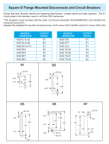
FIG. 3 : Panel Drilling, in
A Vertical center line of the operating handle drilling. See the handle instruction bulletin.
D
Distance from the handle mounting surface to the circuit breaker mounting surface.
Min. = 10.5 in. (267 mm)
Max. = 18.9 in. (480 mm)
N Circuit breaker mounting surface
P Handle mounting surface
Q Circuit breaker
R4 holes, 1/4 – 20 tap, extruded in 13 gauge or thinner, for mounting the frame of the operating mecha
nism
S 4 clearance holes, 0.31 (7.9) diameter, for #10 circuit breaker screws
T Door
XWire bending space from the top of circuit breaker to the inside wall or barrier. Refer to NEC Article 4
30-10 for the table based on the size and number of conductors.
Cable Operating Mechanisms

Type Cable Length
CMP40 48 (1219)
CMP50 60 (1524)
CMP10 120 (3048)
NOTE: For circuit breakers with a trip unit adjust option, refer to page 2 and complete the installation.
DANGER
HAZARD OF ELECTRIC SHOCK, EXPLOSION, OR ARC FLASH
After installation, verify that the door cannot be opened with the operating handle and circuit breaker in the On
position.
Failure to follow these instructions will result in death or serious injury.
Electrical equipment must be installed, operated, serviced, and maintained only by qualified personnel. No
responsibility is assumed by Schneider Electric for any consequences arising out of the use of this material.
Schneider Electric, Square D, PowerPacT, and Visi-Trip are trademarks and the property of Schneider Electric SE,
its subsidiaries, and affiliated companies. All other trademarks are the property of their respective owners.
Schneider Electric USA, Inc.
800 Federal Street
Andover, MA 01810 USA
888-778-2733
www.se.com/us
© 2008–2022 Schneider Electric All Rights Reserved
Documents / Resources
SQUARE D 9422CMP50 Disconnect Mechanism Circuit Breaker Cable Operated [pdf] Instr
uction Manual
9422CMP50 Disconnect Mechanism Circuit Breaker Cable Operated, 9422CMP50, Disconnect
Mechanism Circuit Breaker Cable Operated, Mechanism Circuit Breaker Cable Operated, Circu
it Breaker Cable Operated, Breaker Cable Operated, Cable Operated, Operated
References
Schneider Electric Canada | Global Specialist in Energy Management and Automation
Schneider Electric Mexico | Servicios de Renovación y Retrofit de Schneider Electric
Schneider Electric USA | Global Specialist in Energy Management and Automation
Manuals+,
/