Page is loading ...

Söll Vi-Go
Vertical Arrest Sytstem
INSTALLATION
GUIDE


INDEX
EN
ES
FR
English 14
Español 20
Français 26
Checklist for acceptance 30
Product Marking 32

4
11

5
6
22

6
5
7
8
3
2
1
33

7
6
9
87
1
3
4
3
5
32
3
4
1
2
44
55

8
7
7
8
8
9
9
1
2
3
1111
43
8
9
1
10
11
12
5
13
6
7
2
10
6
6
1212
1010

9
1234
5
6
1111
1
2
3
4
5
1313
1
2
1212
5 22 5 225 225 22
4. 3. 2. 1.
Cable
10 mm
10 14,5 10 14,510 14,5
3. 2. 1.
Cable
8 mm
11,3
4. 3. 2. 1.
5.
3 93 93 93 9912,5
The 10 mm cable is not swaged
with the electric swaging machine
mm
11,3
15,6
1010

10
12
10 21110 98
98
13
7
4
3
56
4
3
56
14
14
2505 mm
1310 mm
15
15

11
4
3
2
1
1616
4
3
5
6
3
5
6
1717
1818 1919
12
10
11
10
9
8
2
4
7
3
5
6

12
INSTRUCTIONS FOR USE
Söll ViGo - Vertical Arrest System
1 GENERAL INFORMATION
1. 1 TECHNICAL DATA
The safety distance between the users must not be less than 3 m (10 ft).
The maximum dynamic load in case of a fall from a height is 6 kN (1345.8 lbf) for one person and + 1 kN (224.8 lbf) for every additional person,
using the system.
Every user of the Söll ViGo vertical arrest system must read and understand this guide before using the system. Actions contravening this guide
may put people’s lives at risk. Users must be trained based on the operating instructions and this user information before starting work and at
regular intervals, however they must be trained no less frequently than once per year.
The operating company of the Söll ViGo vertical arrest system and the user of the fall arrester must ensure that this guide is kept along with the
corresponding fall arrester on a dry and readily accessible place.
The Söll ViGo vertical arrest system must be used only with fall arresters of Söll ViGo vertical systems depending on cable diameter and type
of the intermediate brackets used as follows.
Tab 1.1 Söll ViGo systems compability
Arrester 8 mm (5/16")
cable 9x17
10 mm (3/8")
cable 9x17
Automatic
bracket
Manual
bracket
VC300
VC3003/8R
VC500
ViGo
The operating company must present this guide at the request of the manufacturer Honeywell Fall Protection Deutschland GmbH & Co. KG
or one of its authorized dealers).It must be supplied with the adequate fall arresters of Söll ViGo vertical arrest systems . The fall arrester that
comes with the Söll ViGo system must be operated only in original Söll ViGo fall protection systems that have the Söll ViGo type ANSI/CSA
prototype test certificate. Using systems of other manufacturers may hamper the functioning of the fall arrester. In such cases, Honeywell
Fall Protection Deutschland GmbH & Co. KG and its authorised dealers shall refuse product liability. The operating company shall then be
completely responsible.
The fall protection system must be used only in conjunction with full body harnesses that have been checked and approved in accordance with
ANSI Z359.11/CSA Z259.10 and are equipped with a climbing attachment point.
The fall arrester of Söll ViGo vertical arrest system must always be attached to the climbing attachment point of the full body harness. The fall
protection system must be handled with care.
The rope attachment points of the ViGo system must not be used as a transport anchor or for fastening loads. Functional capability of the sys-
tem must be inspected visually before and while using the installed fall protection system. The operating company of the fall protection system
must ensure that a rescue plan (that takes into account all possible emergencies which may occur when working) is available.
Operating temperature: 40 °C to +70°C (40 °F to +158 °F); here, ensure that the system is free of greases, oils and ice.
The user must be in good health and must not be under the influence of alcohol, drugs or medicines. Corresponding instructions must be
followed if other personal protective equipment is used.
The checklist (page 88) must be filled by the manager of the installation company completely and properly using an indelible pen.
In case of a test mass of 100 kg (220 lbs) and a situation where the falling factor is 2 (conditions of the most unfavourable fall), a height of at
least 2.0 m (6.6 ft) is required below the user’s feet.
Important!
Before using the fall protection system, ensure that the required free space of 2.0 m (6.6 ft) under the user's feet is available. The user may
not be sufficiently protected against hitting the ground or obstacles if he/she is at a height of less than 2.0 m (6.6 ft).
1. 2 PRINCIPLE SKETCH OF THE SÖLL ViGo VERTICAL ARREST SYSTEM (See Fig.1)
1) Manual Intermediate bracket Galvanized Steel(VGMB3/8GS) / Manual Intermediate bracket Stainless Steel (VGMB3/8SS)
2) Universal Top Rung Brack Galvanized steel (VGTBGS) / Universal Top Rung Brack Stainless steel (VGTBSS)
3) Heavy Duty Tensioner Galvanized steel (VGBB3/8GS) / Heavy Duty Tensioner (VGBB3/8SS)
Maximum rope length 200 m (696 ft)
Fixing span We recommend a maximum fixing span of 10 m (33 ft) for internal ladders
and maximum 3 to 4 m (10 to 13 ft) for external fall protection systems respectively.
Maximum number of users 3; depending on the load bearing capacity of the substructure
EN

13
EN
1. 3 PRINCIPLE SKETCH OF THE SÖLL ViGo VERTICAL ARREST SYSTEM WITH THE EXTENSION POST (See Fig. 2)
1) Platform Extension Galvanized Steel (VGPEGS) / Platform Extension Stainless Steel (VGPESS)
1. 4 INSTALLATION
The Söll ViGo vertical arrest system is installed vertically on ladders.
The following parameters must be kept in mind during installation:
• Maximum rope length (200 m (696 ft))
• Adequate rope tension (1400 to 1600N / 314 to 360 lbf); The tension reading on the rope tensioner must be between the minimum and
maximum markings.
• Stability of the substructure
• The maximum angle of the cable installation is 15° from the vertical.
• Maximum number of simultaneous users who are secured against falling by the system (see the ID plate)
• The maximum distance between two intermediate brackets is 10 m (33 ft). The intermediate brackets reduce and limit the deflections of
the steel cable. The deflection of the system depends on the total length and the wind speed. To avoid damage, the intermediate brackets
must ensure that the cable is not touching the construction.
• For longer systems and in regions with high wind speed, we recommend shorter distances between the intermediate brackets.
−Systems length up to 55 m (180 ft), 4 m (13 ft) between the intermediate brackets.
−Systems length more than 55 m (180 ft), 3 m (10 ft) between the intermediate brackets.
−If the wind speed is more than 130 km/h (80 mph), 3 m (10 ft) between the intermediate brackets.
• These are recommendations. If the cable is not touching the steel structure, the maximum distance between the intermediates can be
used.
• The height below the user’s feet when using the fall protection system: 2.0 m (6.6 ft)
• The upper rope anchor point must always be above the person to be secured.
An overview of components is given below (see Fig.3):
1) Guided type fall arrester
2) Cable tensioner
3) Steel cable
5) Universal Rung Bracket
7) Cable terminal
8) Manual intermediate bracket
1. 5 SUBSTRUCTURE
Before installation, check whether the component on which the Söll ViGo vertical arrest system is to be fixed can withstand the loads resulting
from a fall (stability certificate). A qualified engineer must certify this. The following characteristic loads resulting from the dynamic loads due
to a fall, user loads and dead-weights of system components serve as the basis for the stability certificate: For fastening the upper end of the
cable; loads working vertically downwards:
For fastening the intermediate bracket and the lower end of the cable, independent of the number of users, effective in each direction:
Fc2 = 1.5 kN / 337 lbf
Warning!
The cable end attachments must always be fastened on sufficiently dimensioned substructures.
1. 6 ADDITIONAL EQUIPMENT
In addition to the fall arrester of Söll ViGo vertical arrest system, the users must be equipped with personal protective equipment (PPE) compli-
ant with the prevailing norms so that they can use the Söll ViGo vertical arrest system safely:
• One full body harness, tested as per ANSI Z359.11 / CSA Z259.10 and equipped with a climbing attachment point
• One self-locking ANSI Z359.12 / CSA Z259.12 compliant connector
1. 7 REFERENCES TO STANDARDS
The Söll ViGo vertical arrest system complies with the ANSI A14.3/ CSA Z259.2.5 standard.
The Extension Post of the Söll ViGo vertical arrest system has been approved as a single anchorage point for one person.
1. 8 OPERATING CONDITIONS
The cable, the cable tension, the fall arrester, the intermediate fixings and the carabiners must be checked for their usability before every use.
If defects are identified or there is any doubt regarding the flawless condition, the fall protection system must be checked by an expert and the
parts must be replaced if required.
Before and while climbing, safe and effective implementation of rescue measures must be ensured.
The fall arrester of Söll ViGo vertical arrest system should not be left on the system. Flawless functioning of the shuttle, especially whether it
properly locks on the cable, must be checked before every use.
Every user must be secured with a separate fall arrester of Söll ViGo vertical arrest system.
Number of simultaneous users 1 2 3
Characteristic vertical load Fc1 10.0 kN / 2,248 lbf 10.5 kN / 3,397 lbf 11.5 kN / 2,547 lbf
Characteristic vertical load with
safety factor k=1.5 15.0 kN / 3,372 lbf 16.0 kN / 3,596 lbf 17.0 kN / 3,821 lbf

14
In conjunction with the full body harness, the fall protection system secures the users against falling when climbing or descending.
When working in or next to the ascent route and during jobs and actions that are not a part of the usual ascent and descent movements, the
climber must additionally secure himself / herself with a lanyard in accordance with ANSI Z359.11/ CSA Z259.11 or a lanyard for safety harness
in accordance with ANSI Z359.3/ CSA Z259.1. This is also applicable for idle positions that are intended to be a break on the fall arrest ladder.
Only suitable anchor devices must be used for this. In all these situations, the lanyard must be held tight in order to prevent a fall. Check the
specifications on the ID plate affixed on the system to determine the maximum number of users.
Important!
An ANSI A14.3/ CSA Z259.2.5 compliant fall protection system should be used by only those persons who are trained and/or are experts or
who are directly supervised by a trained and/or expert person.
1. 9 QUALITY CHECKS AND WARRANTY
All parts of the Söll ViGo vertical arrest system have been manufactured in compliance with ISO 9001 quality checks and ISO 14001 environ-
ment management. Individual identification of all ViGo components guarantees their complete traceability.
In the delivery condition, all metallic parts of the fall protection system are made of galvanized or stainless steel. A warranty of two years against
manufacturing defects is given under normal operating conditions (an exceptionally corrosive atmosphere can reduce this period). In case of
any doubt, please contact Honeywell Fall Protection. The warranty period starts on the date on which the installer hands over the Söll ViGo
vertical arrest system to the owner. The installer is under obligation to maintain the documentation of handing over the fall protection system.
The manufacturer’s warranty for the parts shall be void if the installation is improper or does not comply with the installation instructions pre-
scribed by Honeywell Fall Protection.
The manufacturer’s warranty does not cover replacement of damaged parts due to a fall or any other improper use.
Note: Honeywell Fall Protection does not bear any warranty for the installation of the fall protection system.
2 INSTALLING THE FALL PROTECTION SYSTEM
2. 1 TOOLS
Minimum tools required for installing the Söll ViGo fall protection system:
• 19 mm (3/4’’) spanner
• open ring wrench
• 19 mm (3/4’’) open spanner
• ratchet including 10 mm (3/8") and 17 mm (11/16”) socket
• torque spanner
• cable cutter
• swaging machine 700 bar (10.15 ksi) hydraulic or 130 kN
(29,255 lbf) electric
• adhesive tape for marking the crimping length
• hot air stream, an alternative lighter for fixing the shrink-fit
hose
2. 2 BASIC PRINCIPLES
At least two persons are required for installing the Söll ViGo vertical arrest system. When installing, all measures must be taken for preventing
the tools and system parts from falling.
2. 3 STARTING THE INSTALLATION
Checking the dimensions and measurements:
Before starting work on the construction site, dimensions specified in the installation plan must be checked (e.g. total length of the fall protec-
tion system, distances between the end and intermediate brackets, etc.).
2. 4 DESCRIPTION OF INSTALLATION
2. 4. 1INSTALLING THE RUNG CLAMPS
It must be ensured that the rung fastening is fixed perpendicular to the rungs.
Assembly (Fig. 4)
1) Hexagon head screw, M12x40 (7/16"14x2")
2) Large washer, 13 (7/16")
3) Washer, 13 (7/16")
4) Sleeve
5) Nut, M12 (7/16"14), self-securing
6) U bolt M10 (3/8''16 x 11/2'' x 21/2'')
7) Washer, 10.5 (3/8")
8) Nut, M10 (3/8"16), self-securing
9) Rung Bracket
Installation
For installing the rung clamps, place the rung bracket (9) on the rungs and fix it on the UBolts (6) behind the rungs. For this, insert the washers
(7) and tighten the M10 (3/8"16) nuts (8).
For tightening the self-securing nuts, we recommend a tightening torque of 40 Nm (29.5 lbf*ft) for steel ladders and 20 Nm (14.75 lbf*ft) for
aluminum ladders.
2. 4. 2INSTALLING THE INTERMEDIATE BRACKETS
INTERMEDIATE BRACKET
Assembly (Fig. 5)
1) Manual bracket
2) U bolt M10 (3/8''16 x 11/2'' x 21/2'')
3) Nut, M10 (3/8"16), self-securing
4) Washer, 10.5 (3/8”)

15
EN
Installation
Align the intermediate bracket such that the cable guide is parallel to the cable and the arrow as shown in Figure 5.
Place the bracket (1) onto a rung with and insert a properly tensioned cable into a bracket slot. Adjust the position of the bracket so the ca-
ble is kept straight. Guide the M10 (3/8''16 x 11/2'' x 21/2'') U bolt (2) through the provided holes, insert the washers (4) and tighten the
M10 (3/8"16) nuts (3).
2. 4. 3INSTALLING THE CABLE TENSIONER
Assembly (Fig.6)
Installation
Install the mounting plate (1) (Figure 6) using the U-bolts (2), and washer (3) and nut (4). Turn with the nut (11) and nut (12) to place them on
the bottom end of the threaded rod (5) (The parts (8), (9), (10), (11) and (12) are already mounted on the threaded rod (5)). Unbolt the nuts (7)
from u-bolts (8) and secure them. Lift the threaded rod to the upmost position. Tighten the rope (13) by hand and secure it to the threaded rod
(5) by nuts (7) and u-bolts (8). Tighten the nuts (7).
Note:
Before making a cable end (using a cable end part for crimping or screwing or using clamps) and hanging it in the lower fastening point, ensure
that it is pushed through the cable guides of all the intermediate brackets that are provided.
Tighten the long nut (11) until the large washer (9) is aligned with a recess in the Mounting plate (1) as (Fig 7). Tighten the counter nut (12)
against the long nut (11). The cable will then be adequately pre-tensioned with 1500 N (337 lbf).
Note:
The rope of a vertical cable system must be installed with a specific cable pre- tension to ensure that the shuttle functions. For the Söll ViGo
vertical arrest system, the prescribed pre-tension is 1500 N (+/- 100 N) (337 lbf +/22lbf).
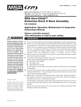
2. 4. 4INSTALLING THE CABLE FACTORYFITTED (Fig. 8)
CABLE CRIMPING
The cable end is crimped in the factory. The cable crimping is normally used only as the upper cable end.
CABLE END PART FOR CRIMPING
Assembly (Fig.9)
Installation (Fig.10)
Crimping the end piece on the cable is a critical process when installing the fall protection system. The strength of the fall protection system
largely depends on the quality of crimping. We therefore recommend adhering to the following suggestions:
Crimping should preferably be done on the ground and, if possible, before transporting the cable to the installation site.
A hexagon head crimping tool is used for crimping. Distances between the crimpings must be maintained (see figure 15).
Insert the cable end in the cable end part to be crimped and mark the cable at the beginning of the cable end part using an adhesive tape.
Then check the length of the cable to be crimped. It must be a minimum of 75 mm (2.9"). Then reinsert the cable into the cable end piece to be
crimped up to the marking (adhesive tape).
Hold the cable end part in the press and actuate the press. Repeat this process two more times and ensure that the required distance of 10 mm
(3/8") between the crimpings is maintained.
Important:
After every crimping, slip indicator ring on the cable so that the loads can be checked later. Slide the ring on the cable before crimping.
If there is any doubt regarding the crimping quality, repeat the process using a new cable and a new part to be crimped.
Note: Never use an already crimped part again.
SWAGELESS CABLE END
Assembly (Fig. 11)
Installation
First slide the jaw housing (5) over the steel cable (6). Then slide the jaws (4) over the cable at regular intervals and place the pressure ring (3)
on the cable. Ensure that the distance between the pressure ring (3) and the end of the cable is 5 mm (1/4”).
Slide the jaw housing (5) over the jaws (4), and screw the eye bolt (1) and the locknut (2) into the jaw housing (5). Now unscrew the locknut and
check the cable position. Add silicon if waterproof attribute is required. If the cable is in incorrect position, repeat whole process.
At the end tighten the locknut (2) using a key to 58Nm (42.775 lbf*ft).

16
CABLE END WITH CABLE GRIPS
Assembly (Fig.12)
Installation
Four cable grips and one thimble are required for making a cable loop (see figure 12). Lay the rope (1) around the thimble (2) to make a loop
and join both rope strings using cable grips.
Guide the U-bolt (3) enclosing both the ends through the holes provided in the block (4), insert the washers (5) and tighten the M5 nuts (6).
Always ensure that the operating cable is mounted next to the blocks and the free- end of the cable is mounted next to the U-bolts.
The distance between the cable clamps should be 6 to 8-times the cable diameter (60 to 80 mm (2.4” to 3”)).
After preparing the cable loops, cover both the rope ends with a shrink-fit hose (Ø 9,5 mm (3/8") for an 8 mm (5/16") cable and Ø 12,7 mm
(1/2") for a 10 mm (3/8") cable)(Fig. 13).
2. 4. 5INSTALLING THE EXTENSION POST
The Söll ViGo Extension Post is a EN 3531:2014 compliant vertical fall protection system and permitted for a maximum of four users.
In addition, the Extension Post is certified as a single anchorage point for one person. The large eye of the post (13 in figure 14) serves as the
anchorage point, providing fall protection when transferring to and from the system.
When used as a single anchorage point, a maximum of one user and a maximum anchoring force of 22 kN (4,945 lbf) are permitted.
The single anchorage point can also be used for anchoring the rescue devices.
2. 4. 6Assembly (Fig. 14)
2. 4. 7Installation
Fix the Extension Post using the rear clamps and the front plates.
Fix the upper fastening point to the uppermost ladder rung and the lower fastening point to the fifth rung from the top. (Fig. 15)
The distance between the top ladder rung and the top end of the Extension Post should be a maximum of 1310 mm (4.3 ft).
If the Extension Post is mounted on an aluminium ladder, use M16 (3/4’’11) threaded bars to strengthen the ladder rungs on which the upper
and lower fastening points of the Extension Post are located.
Guide the threaded rod (2) through the corresponding rung (1) and fix it on both sides using washers (3) and M16 (3/4’’11) nuts (4).(Fig. 16)
Use the rear clamp (3) to fasten the lower end of the Extension Post (figure 22). Guide it on the rung from behind and fix it using the M10 hex-
agon head screws (4), washers (5) and the M10 (3/8"16) nuts (6).
Then fasten the Extension Post on the top rung of the ladder and on the third rung from top as shown in figure 18.
Fix the front plate (7) on the Extension Post (1) from the front. Use the M10 (3/8"16) hexagon head screws (4), washers (5) and nuts (6) for
connecting it to the rear clamp (3) provided behind the rung.
In order to fasten the upper cable end, insert the sleeve (11) into the rope eye and fix the rope on the attachment point (2) using the M12
(7/16”14) hexagon head screw (8), the large washer (9), the two small washers (10) and the M12 (7/16”14) nut (12) as shown in figure 19..
3 MAINTANANCE
3. 1 ACCEPTANCE
CHECKLIST FOR ACCEPTANCE
Söll ViGo vertical arrest system compliant with ANSI A14.3.
The site manager of the installation company must fill the checklist completely using an indelible pen. The site manager is responsible for the
correctness of all data. If a checkpoint is answered with “no”, it must be clarified in the “comments” section in the list on page 38.
3. 2 REGULAR INSPECTION
A fall protection system subjected to a fall may be used again only after examination by a Competent Person. The fall arrester check/acceptance
sheet must be sent to the manufacturer’s workshop for checking and maintenance.
Depending on the application and operating conditions, a Competent Person must check the fall protection system for its flawless condition as
and when required, and at least once a year. It may be repaired only in the manufacturer’s workshop owing to safety reasons.
A Competent Person is:
“a person who has adequate knowledge in the area of personal safety equipment for protection against falling owing to his/her technical ed-
ucation (e.g. participation in and successful completion of a training program) and experience and who is knowledgeable about the prevailing
national industrial safety regulations, accident prevention regulations, guidelines and generally acceptable technical standards (e.g. standards,
-specifications, technical regulations) to such an extent that he/she can assess the safe working condition and proper use of personal safety
equipment for protection against falls from a height.”
To check the fall arrester of Söll ViGo vertical arrest system functionality refer the User Guide of appropriate Fall Arrester.
3. 3 STORING THE SHUTTLE
Proper care of your PPE will ensure longer life of the product and your safety. Be sure to adhere strictly to these guidelines: Clean with water
and mild soap. Do not use any solvents or acid/alkaline containing cleansing agents under any circumstances. Allow to dry naturally in a
well-ventilated area away from any open fire or other sources of heat. Do not wash it with a quick cleaner, thinner or degreaser containing
trichloroethane. Do not use grease.

17
EN
The fall arrester of Söll ViGo vertical arrest system that comes with the Söll ViGo system should be cleaned, should be as dry and dust-free as
possible, and should be stored in a cool place.
3. 4 LIFESPAN
The maximum life of PPE that is predominantly metal is evaluated as being unlimited but, however, this maximal life is reduced to 10 years
after the date of manufacture for non-opening products. However, there are factors that can considerably reduce the strength of the product
and shorten its life: incorrect storage, incorrect use, fall arrest, mechanical deformation, product fall from a height, wear, electric conductivity,
contact with chemical products (acids and alkalis) or sharp edges, exposure to strong sources of heat > 70°C (158 °F), UVs, abrasion, etc.
If your PPE has been exposed to any of the foregoing conditions, inspect it to ensure that it remains in flawless condition.
4 INDEX OF PARTS
For further information about the product and reference numbers of spare parts please visit our website.

18
INSTRUCCIONES DE USO
Söll ViGo - Sistema anticaídas vertical
1 INFORMACIÓN GENERAL
1. 1 DATOS TÉCNICOS
La distancia entre los usuarios no puede ser inferior a los 10 ft/3 m.
La carga dinámica máxima en caso de caída desde altura es de 6 kN para una persona y + 1 kN por cada persona adicional que esté usando el
sistema. Todos los usuarios del sistema anticaídas vertical Söll ViGo deben leer y comprender esta guía antes de utilizar el sistema. Cualquier
acción que incumpla las especificaciones de esta guía puede poner vidas humanas en peligro. Los usuarios deben recibir formación que abar-
que estas las instrucciones de operación y esta información de usuario antes de comenzar a trabajar y a intervalos regulares, y también deben
ser recibir capacitación al menos una vez al año.
La empresa operadora del sistema anticaídas vertical Söll ViGo y el usuario del dispositivo anticaídas deben asegurarse de que esta guía se
conserve junto con el dispositivo anticaídas correspondiente en un lugar seco y de fácil acceso.
Solo se debe usar el sistema de detención vertical Söll ViGo con los siguientes dispositivos anticaídas de los sistemas verticales Söll ViGo en
función del diámetro del cable y el tipo de los soportes intermedios que se utilicen como se indica a continuación.
Tab. 1.1 Compatibilidad de sistemas Söll ViGo
Sistema de
detención
8mm
Cable 9x17
10mm
Cable 9x17
Abrazadera
automática
Abrazadera
manual
VC300
VC3003/8R
VC500
ViGo
La empresa operadora debe presentar esta guía a petición del fabricante Honeywell Fall Protection Deutschland GmbH & Co. KG o de uno de
sus distribuidores autorizados). Se debe suministrar con los anticaídas adecuados de los sistemas anticaídas verticales Söll ViGo. Solo se
debe utilizar el anticaídas suministrado con el sistema ViGo de Söll en combinación con sistemas de protección anticaídas originales de Söll
ViGo que tengan el certificado de prueba de prototipos de Söll ViGo tipo EN/ANSI/CSA. El uso de sistemas de otros fabricantes puede afectar
negativamente al funcionamiento del dispositivo anticaídas. En estos casos, Honeywell Fall Protection Deutschland GmbH & Co. KG y sus
distribuidores autorizados rechazarán la responsabilidad del producto. Se hará responsable a la empresa operadora.
El sistema de protección anticaídas solo debe utilizarse en combinación con arneses de cuerpo completo que hayan sido comprobados y apro-
bados de conformidad con la norma ANSI Z359.11/CSA Z259.10 y estén equipados con un punto de enganche frontal.
El dispositivo anticaídas que viene con el sistema anticaídas vertical Söll ViGo debe estar siempre conectado al punto de enganche de escala-
da del arnés de cuerpo completo. El sistema de protección anticaídas se debe manejar con cuidado.
Los puntos de enganche de la cuerda del sistema ViGo no se deben usar como anclaje de transporte ni para fijar cargas. Se debe inspeccionar
visualmente la capacidad funcional del sistema antes y durante el uso del sistema de protección contra caídas instalado. La empresa opera-
dora del sistema de protección anticaídas debe asegurarse de que hay disponible un plan de rescate (que tenga en cuenta todas las posibles
emergencias que puedan producirse durante el trabajo).
Temperatura de funcionamiento: 40 °C a +70°C; asegúrese de que el sistema esté libre de grasa, aceite y hielo.
El usuario debe encontrarse en buen estado de salud y no estar bajo la influencia de alcohol, drogas ni medicación. Si se utiliza otro equipo de
protección personal, se deben seguir las instrucciones correspondientes.
El responsable de la empresa instaladora debe rellenar la lista de verificación de forma completa y adecuada utilizando un bolígrafo indeleble.
En caso de usar una masa de prueba de 100 kg y una situación en la que el factor de caída es 2 (condiciones de caída más desfavorables), se
requiere una altura mínima de 2,0 m por debajo de los pies del usuario.
Importante
Antes de usar el sistema de protección contra caídas, asegúrese de disponer del espacio libre requerido de 2,0 m bajo los pies del usuario.
Es posible que el usuario no esté suficientemente protegido contra los golpes en el suelo o los obstáculos si se encuentra a una altura
inferior a 2,0 m.
Longitud máxima de la cuerda 200 m
Tramo de fijación Recomendamos un tramo de fijación máximo de 10 m para escaleras internas y un
máximo de 3 a 4 m para sistemas externos de protección contra caídas respectivamente.
Numero maximo de usuarios 3; dependiendo de la capacidad de carga de la subestructura
ES

19
ES
1. 2 ESQUEMA PRINCIPAL DEL SISTEMA ANTICAÍDAS VERTICAL ViGo DE SÖLL (ver fig.1)
1) Soporte intermedio manual Acero galvanizado (VGMB3/8GS) / Soporte intermedio manual Acero inoxidable (VGMB3/8SS)
2) Soporte universal para peldaños superior Acero galvanizado (VGTBGS) / Soporte universal para peldaños superior Acero inoxidable (VGTBSS)
3) Tensor de servicio pesado Acero galvanizado (VGBB3/8GS) / Tensor de servicio pesado (VGBB3/8SS)
1. 3 ESQUEMA PRINCIPAL DEL SISTEMA ANTICAÍDAS VERTICAL ViGo DE SÖLL CON EL POSTE DE
EXTENSIÓN (ver fig.2)
1) Extensión de plataforma de acero galvanizado (VGPEGS) / Extensión de plataforma de acero inoxidable (VGPESS)
1. 4 INSTALACIÓN
El sistema anticaídas vertical Söll ViGo se instala verticalmente en escalerillas. Durante la instalación hay que tener en cuenta los siguientes
parámetros:
• Longitud máxima de la cuerda (200 m)
• Tensión adecuada de la cuerda (1400 a 1600N); La lectura de la tensión en el tensor de la cuerda debe estar entre las marcas mínimas
y máximas.
• Estabilidad de la subestructura
• El ángulo máximo de la instalación del cable es de 15° desde la vertical.
• Número máximo de usuarios que el sistema puede proteger simultáneamente contra caídas (ver la placa de identificación)
• La distancia máxima entre dos soportes intermedios es de 10 metros. Los soportes intermedios reducen y limitan las deflexiones del
cable de acero. La deflexión del sistema depende de la longitud total y de la velocidad del viento. Los puntos intermedios deben evitar que
el cable toque la construcción y pueda dañarse.
• Para sistemas más largos y en regiones con vientos de altas velocidades, recomendamos distancias más cortas entre los soportes in-
termedios.
−Sistemas de hasta 55 m de longitud, 4 m entre las abrazaderas intermedias.
−Sistemas de hasta 55 m de longitud, 3 m entre las abrazaderas intermedias.
−Sistemas de hasta 130 km de longitud/, 3 m entre las abrazaderas intermedias.
• Estas son recomendaciones. Si está garantizado que el cable no tocará la estructura de acero, se puede usar la distancia máxima entre
las abrazaderas intermedias.
• Altura por debajo de los pies de los usuarios cuando usen el sistema de protección anticaídas. 2,0 m
El punto de anclaje superior de la cuerda siempre debe quedar por encima de la persona enganchada. A continuación, se muestra un resumen
de los componentes (ver fig. 3):
1) Dispositivo anticaídas deslizante
2) Tensor de cable
3) Cable de acero
5) Soporte de peldaño universal
7) Terminal de cable
8) Abrazadera intermedia manual.
1. 5 SUBESTRUCTURA
Antes de la instalación, compruebe si el componente en el que se va a fijar el sistema anticaídas vertical Söll ViGo puede soportar las cargas
resultantes de una caída (certificado de estabilidad). Un ingeniero cualificado debe certificarlo. El certificado de estabilidad se basará en las
siguientes cargas características resultantes de las cargas dinámicas debidas a una caída, las cargas de usuario y los pesos muertos de los
componentes. Para la fijación del extremo superior del cable; cargas que trabajan verticalmente hacia abajo:
Para la fijación de la abrazadera intermedia y el extremo inferior del cable, independientemente del número de usuarios, efectivo en ambas
direcciones.Fc2 = 1,5 kN
¡Cuidado!
Las fijaciones de los extremos de los cables deben estar siempre sujetas a subestructuras suficientemente dimensionadas.
1. 6 EQUIPO ADICIONAL
Además del anticaídas del sistema anticaídas vertical Söll ViGo, los usuarios deben llevar equipos de protección personal (EPP) que cumplan
las normas vigentes para poder utilizar el sistema anticaídas vertical Söll ViGo de forma segura:
• Un arnés de cuerpo completo, probado según ANSI Z359.11 / CSA Z259.10 y equipado con un punto de fijación para escalar
• Un conector autobloqueante conforme a la norma ANSI Z359.12 / CSA Z259.12
1. 7 REFERENCIAS A NORMAS
El sistema anticaídas vertical Söll ViGo cumple con la norma ANSI A14.3/ CSA Z259.2.5.
El poste de extensión del sistema anticaídas vertical Söll ViGo ha sido aprobado como punto de anclaje único para una persona.
Número de usuarios a la vez 1 2 3
Carga característica vertical Fc1 10.0 kN 10.5 kN 11.5 kN
Carga característica vertical con
factor de seguridad k = 1,5 15.0 kN 16.0 kN 17.0 kN

20
1. 8 CONDICIONES DE FUNCIONAMIENTO
Se debe comprobar la funcionalidad del cable, la tensión del cable, el anticaídas, las fijaciones intermedias y los mosquetones antes de cada
uso. Si se identifican defectos o existe alguna duda sobre su estado impecable, el sistema de protección anticaídas debe ser comprobado por
un experto y, si es necesario, reemplazar las piezas que fallen.
Antes y durante la escalada, se debe garantizar la aplicación segura y eficaz de las medidas de rescate.
El dispositivo anticaídas del sistema anticaídas vertical Söll ViGo es un dispositivo que pertenece al equipo de protección personal y no debe
dejarse en el sistema. Antes de cada uso, se debe comprobar el perfecto funcionamiento del dispositivo, especialmente si se bloquea correc-
tamente en el cable.
Los usuarios deben estar protegidos con un anticaídas independiente del sistema de detención vertical ViGo de Söll.
Junto con el arnés de cuerpo completo, el sistema de protección anticaídas asegura a los usuarios contra las caídas al subir o bajar.
Si se trabaja en una ruta de ascenso o cerca de esta, y durante trabajos y acciones que no formen parte de los movimientos habituales de
ascenso y descenso, el operario debe protegerse además con una cuerda, conforme con ANSI Z359.11/ CSA Z259.11 o con una cuerda para un
arnés de seguridad conforme con ANSI Z359.3/ CSA Z259.1. Esto también se aplica a posiciones de descanso en la escalerilla anticaídas. Para
esto, solo deben utilizarse dispositivos de anclaje apropiados. En todas estas situaciones, la cuerda se debe sujetar firmemente para prevenir
una caída. Compruebe las especificaciones de la placa de identificación fijada en el sistema para determinar el número máximo de usuarios.
¡Importante!
Un sistema de protección anticaídas conforme a la norma ANSI A14.3/ CSA Z259.2.5 solo puede ser utilizado por personas que capacita-
das o expertas, o que estén directamente supervisadas por una persona capacitada o experta.
1. 9 CONTROLES DE CALIDAD Y GARANTÍA
Todas las partes del sistema anticaídas vertical de Söll ViGo se han producido conforme con los controles de calidad ISO 9001 y la gestión
medioambiental ISO 14001. La identificación individual de todos los componentes del ViGo garantiza su completa trazabilidad.
En la entrega, todas las partes metálicas del sistema de protección anticaídas son de acero galvanizado o inoxidable. Se ofrece una garantía
de dos años contra defectos de fabricación en condiciones de funcionamiento normales (una atmósfera excepcionalmente corrosiva puede
reducir este período). En caso de duda, póngase en contacto con Honeywell Fall Protection. El período de garantía comienza en la fecha en que
el instalador entrega el sistema anticaídas vertical Söll ViGo al propietario. El instalador tiene la obligación de conservar la documentación
de entrega del sistema de protección anticaídas. Si la instalación es incorrecta o no cumple con las instrucciones de instalación prescritas por
Honeywell Fall Protection, la garantía del fabricante de las piezas quedará anulada.
La garantía del fabricante no cubre el reemplazo de las piezas dañadas por caídas o a cualquier otro uso inadecuado.
Nota: Honeywell Fall Protection no incluye ninguna garantía por la instalación del sistema de protección anticaídas.
2 INSTALACIÓN DEL SISTEMA DE PROTECCIÓN ANTICAÍDAS
2. 1 HERRAMIENTAS
Herramientas mínimas necesarias para instalar el sistema de protección anticaídas Söll ViGo:
• Llave de 19 mm (3/4’’)
• Llave de anillo abierto
• Llave abierta de 19 mm (3/4’’)
• Trinquete con hueco de 10 mm (3/8”) y 17 mm (11/16”)
• Llave dinamométrica
• Cortador de cables
• Máquina de estampado 700 bar (10.15 ksi) hidráulica o
130 kN (29,255 lbf) eléctrica
• Cinta adhesiva para marcar la sección de crimpado
• una corriente de aire caliente, un encendedor alternativo
para fijar el tubo retráctil
2. 2 PRINCIPIOS BÁSICOS
Se necesitan al menos dos personas para instalar el sistema anticaídas vertical Söll ViGo. Durante la instalación, se deben tomar todas las
medidas para evitar que se caigan las herramientas y las piezas del sistema.
2. 3 COMIENZO DE LA INSTALACIÓN
Comprobar las dimensiones y medidas:
Antes de comenzar los trabajos en la obra, se deben comprobar las dimensiones especificadas en el plan de instalación (longitud total del
sistema de protección contra caídas, distancias entre los soportes finales e intermedios, etc.).
2. 4 DESCRIPCIÓN DE INSTALACIÓN
2. 4. 1 INSTALACIÓN DE LAS ABRAZADERAS DE PELDAÑO
Debe asegurarse de que la fijación de los peldaños es perpendicular a estos.
Montaje (fig. 4)
1) Tornillo de cabeza hexagonal, M12x40 (7/16"14x2')
2) Arandela grande, 13 (7/16")
3) Arandela, 13 (7/16")
4) Manguito
5) Tuerca, M12 (7/16"), autoblocante
6) Perno en U M10 (3/8''16 x 11/2'' x 21/2'')
7) Arandela, 10.5 (3/8'')
8) Tuerca, M10 (3/8"16), autoblocante
9) Abrazadera de peldaño
/