Lithium Series

Turbo Energy Lithium Series Installation guide

  • Hello! I've reviewed the Quick Installation Guide for the Lithium Series Dual 48V 5.1kWh battery and the Phoenix Inverter Compact. This document outlines the steps for setting up communication between the battery and inverter, including using DIP switches and RJ45 connections. I'm ready to assist with any questions you have about the setup or operation mentioned in the guide.
  • How do I turn on the battery?
    How do I turn off the battery?
    What is SW1 used for?
    What type of cable is used for the connection?
www.turbo-e.com
QUICK INSTALLATION GUIDE
Lithium Series
Dual 48V 5.1kWh
+
Victron Energy Inverter
+
www.turbo-e.com
1. Inverter configuration
The configuration between the inverter and the
battery is quite simple.
In fact, to facilitate the control and operation
of the installation, a GX device is used: COLOR
CONTROL GX, VENUS GX, CERBO GX.
The connection of the communication is made between the master battery and the
Color Control, and from the Color Control to the inverter.
We can use the REGULADOR MPPT BlueSolar /
SmartSolar (VE. Direct)
www.turbo-e.com
Underneath, a complete scheme of connection of all devices is shown.
Lithium Series Dual 48V 5.1kWh
www.turbo-e.com
2. Battery On and Off
To turn on the battery, press the power button for a few seconds. The BMS will start working
and the LED will light up.
To turn off the batteries, press the power button for more than 5 seconds.
3. Setting Lithium Series Dual 48V 5.1 kWh
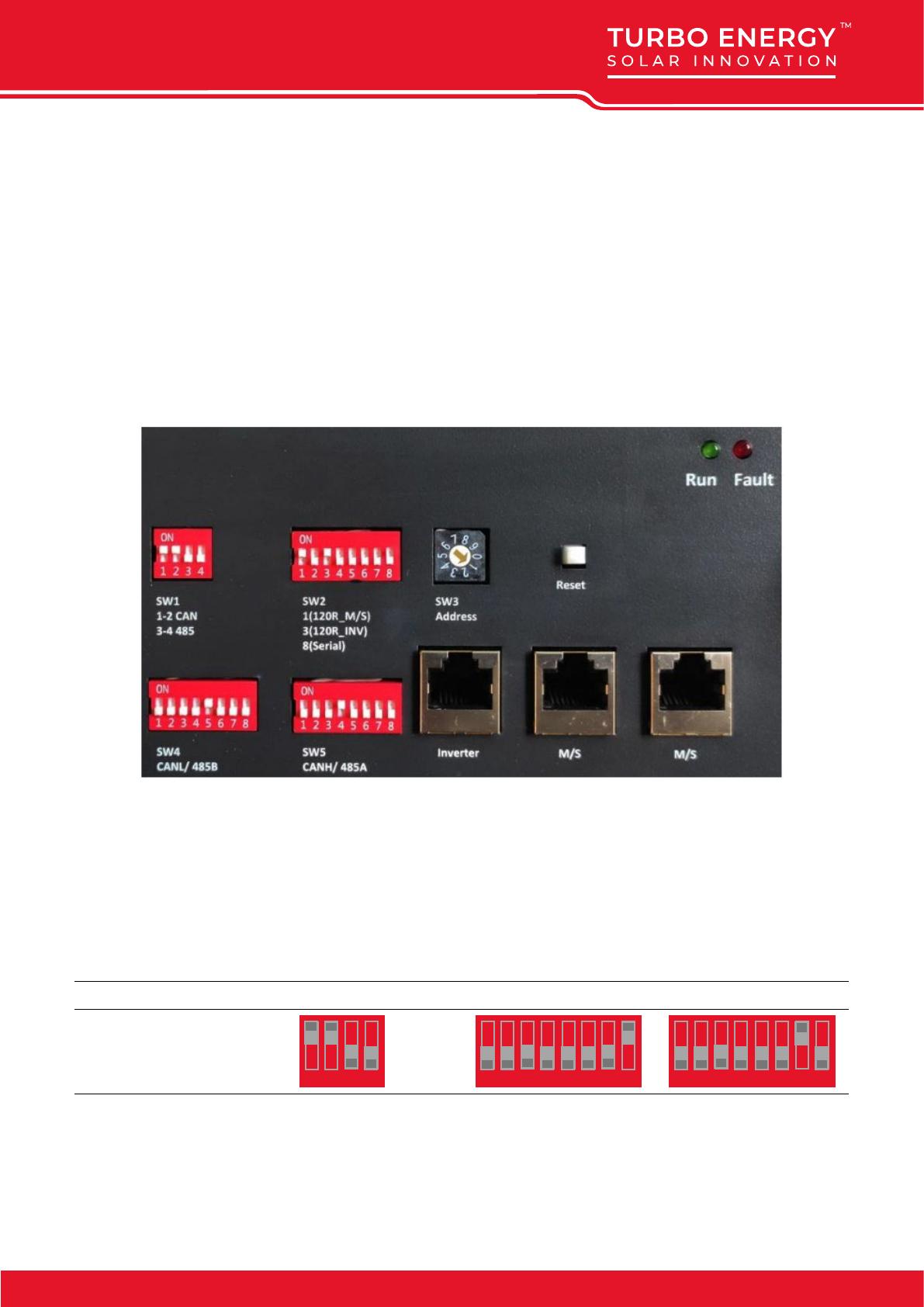
Each module has 5 DIP switches (SW1, SW2, SW3, SW4, and SW5) that will be set differently
based on system requirements, battery connection, and inverter.
SW1 is for the communication protocol with the inverter. If the CAN protocol is used,
1 and 2 must be ON.
SW4 and SW5 are for communication with the inverter and depend on the communication
cable and protocol of the inverter.
If a pin-to-pin cable is used, the DIP settings are as follows:
Protocol SW1 SW4 SW5
CAN
1 2 3 4
1=ON
0=OFF
1 52 63 74 8 1 52 63 74 8
www.turbo-e.com
3.1. DIPS FOR CONNECTION ON PARALLEL
SW2 and SW3 are for communication between batteries.
Connected
Battery
Number
Group SW2
Parallel connect
SW3
Address Set
1-
1 52 63 74 8
1
2
3
4
5
6
7
8
9
0
2
Primary
1 52 63 74 8
1
2
3
4
5
6
7
8
9
0
Sub
1 52 63 74 8
1
2
3
4
5
6
7
8
9
0
3
Primary
1 52 63 74 8
1
2
3
4
5
6
7
8
9
0
Sub1
1 52 63 74 8
1
2
3
4
5
6
7
8
9
0
Sub2
1 52 63 74 8
1
2
3
4
5
6
7
8
9
0
www.turbo-e.com
Connected
Battery
Number
Group SW2
Parallel connect
SW3
Address Set
4
Primary
1 52 63 74 8
1
2
3
4
5
6
7
8
9
0
Sub1
1 52 63 74 8
1
2
3
4
5
6
7
8
9
0
Sub2
1 52 63 74 8
1
2
3
4
5
6
7
8
9
0
Sub3
1 52 63 74 8
1
2
3
4
5
6
7
8
9
0
5
Primary
1 52 63 74 8
1
2
3
4
5
6
7
8
9
0
Sub1
1 52 63 74 8
1
2
3
4
5
6
7
8
9
0
Sub2
1 52 63 74 8
1
2
3
4
5
6
7
8
9
0
Sub3
1 52 63 74 8
1
2
3
4
5
6
7
8
9
0
Sub4
1 52 63 74 8
1
2
3
4
5
6
7
8
9
0
www.turbo-e.com
Connected
Battery
Number
Group SW2
Parallel connect
SW3
Address Set
6
Primary
1 52 63 74 8
1
2
3
4
5
6
7
8
9
0
Sub1
1 52 63 74 8
1
2
3
4
5
6
7
8
9
0
Sub2
1 52 63 74 8
1
2
3
4
5
6
7
8
9
0
Sub3
1 52 63 74 8
1
2
3
4
5
6
7
8
9
0
Sub4
1 52 63 74 8
1
2
3
4
5
6
7
8
9
0
Sub5
1 52 63 74 8
1
2
3
4
5
6
7
8
9
0
www.turbo-e.com
Connected
Battery
Number
Group SW2
Parallel connect
SW3
Address Set
7
Primary
1 52 63 74 8
1
2
3
4
5
6
7
8
9
0
Sub1
1 52 63 74 8
1
2
3
4
5
6
7
8
9
0
Sub2
1 52 63 74 8
1
2
3
4
5
6
7
8
9
0
Sub3
1 52 63 74 8
1
2
3
4
5
6
7
8
9
0
Sub4
1 52 63 74 8
1
2
3
4
5
6
7
8
9
0
Sub5
1 52 63 74 8
1
2
3
4
5
6
7
8
9
0
Sub6
1 52 63 74 8
1
2
3
4
5
6
7
8
9
0
www.turbo-e.com
Connected
Battery
Number
Group SW2
Parallel connect
SW3
Address Set
8
Primary
1 52 63 74 8
1
2
3
4
5
6
7
8
9
0
Sub1
1 52 63 74 8
1
2
3
4
5
6
7
8
9
0
Sub2
1 52 63 74 8
1
2
3
4
5
6
7
8
9
0
Sub3
1 52 63 74 8
1
2
3
4
5
6
7
8
9
0
Sub4
1 52 63 74 8
1
2
3
4
5
6
7
8
9
0
Sub5
1 52 63 74 8
1
2
3
4
5
6
7
8
9
0
Sub6
1 52 63 74 8
1
2
3
4
5
6
7
8
9
0
Sub7
1 52 63 74 8
1
2
3
4
5
6
7
8
9
0
Make sure DIP switch SW2 is selected correctly. If the battery is connected in
parallel mode, but DIP8 is in the ON position, a serious and dangerous fault
may occur. On the other hand, if the battery is connected in serial mode, but
SW2 DIP8 is in the OFF position, a serious and dangerous fault may occur
www.turbo-e.com
4. Wired configuration
The cable needed to make the connection
is the RJ45. This is a cable made up of 8
smaller cables each with a different color
configuration.
A standard pin-to-pin cable with an RJ45
connector should be used.
For the connection between the inverter and
the battery, the RJ45 cable will be connected
to the “Inverter” port of the battery, and to the
CAN port of the inverter
/