Page is loading ...

D-M-CRP5-MODBUS-V1_03
Rotronic AG
Bassersdorf, Switzerland
Document code Unit
Modbus Manual V1.03:
CRP5 Clean Room Panel
Instruction Manual
Document Type
Page 1 of 42
Document title
© 2018- Rotronic AG Modbus CRP5V1.0_03
Modbus Manual Version 1.03
Modbus Manual for Clean Room Panel CRP5
This manual is for persons who will use the Clean Room Panel Modbus protocol. It describes how
messages are constructed and how transactions take place using Modbus protocol.

D-M-CRP5-MODBUS-V1_03
Rotronic AG
Bassersdorf, Switzerland
Document code Unit
Modbus Manual V1.03:
CRP5 Clean Room Panel
Instruction Manual
Document Type
Page 2 of 42
Document title
© 2018- Rotronic AG Modbus CRP5V1.0_03
Table of contents
1 Modbus protocol ............................................................................................................................... 3
1.1 Structure of the Modbus protocol ....................................................................................................... 3
1.1.1 Modbus RTU / TCP ................................................................................................................... 3
1.2 Modbus Data Format ......................................................................................................................... 4
1.2.1 16-bit Integer Value ................................................................................................................... 4
1.2.2 32-bit Float corresponding to IEEE 754 .................................................................................... 4
1.2.3 32-bit Integer Value ................................................................................................................... 4
1.2.4 Selectable Swap Modes for Rotronic Devices........................................................................... 5
2 CRP5 Modbus Fields and Mapping .................................................................................................. 6
2.1 CRP5 Modbus Fields ......................................................................................................................... 6
2.2 Device Specific Coils ......................................................................................................................... 6
2.2.1 Relays 1 to 6 ............................................................................................................................. 6
2.2.2 Valves A to D ............................................................................................................................ 7
2.2.3 Maintenance/Calibration ........................................................................................................... 7
2.2.4 Sensor Actions .......................................................................................................................... 9
2.2.5 Device Actions .........................................................................................................................10
2.2.6 Example: Read Single Coil.......................................................................................................11
2.2.7 Example: Write Single Coil .......................................................................................................12
2.2.8 Example: Write Multiple Coils ...................................................................................................12
2.2.9 Example: Reset Device ............................................................................................................13
2.3 Device Specific Discrete Inputs (read only) ......................................................................................14
2.3.1 Digital Inputs 1 and 2 ...............................................................................................................14
2.3.2 Example: Read Discrete Inputs ................................................................................................14
2.4 Device Specific Input Registers (read only) ......................................................................................15
2.4.1 Device Data..............................................................................................................................15
2.4.2 Current Values: Float Values ...................................................................................................16
2.4.3 Current Values: Integer Values ................................................................................................17
2.4.4 FDA Data .................................................................................................................................18
2.4.5 Example: Read Input Register .................................................................................................19
2.5 Device Specific Holding Registers ....................................................................................................19
2.5.1 Value Type ...............................................................................................................................19
2.5.2 Value Unit.................................................................................................................................21
2.5.3 Integer Value Scaling ...............................................................................................................22
2.5.4 Reference Value Settings ........................................................................................................22
2.5.5 Device Settings ........................................................................................................................22
2.5.6 Device Descriptions .................................................................................................................24
2.5.7 Fix Value Settings ....................................................................................................................26
2.5.8 Analog Output Settings ............................................................................................................27
2.5.9 Display Settings .......................................................................................................................29
2.5.10 Alarm Settings .....................................................................................................................30
2.5.11 Relay Settings ......................................................................................................................32
2.5.12 Analog Input Settings ...........................................................................................................34
2.5.13 Ethernet Settings .................................................................................................................39
2.5.14 Example: Read Holding Register .........................................................................................40
2.5.15 Example: Write Holding Register .........................................................................................41
3 Document Releases ........................................................................................................................ 42

D-M-CRP5-MODBUS-V1_03
Rotronic AG
Bassersdorf, Switzerland
Document code Unit
Modbus Manual V1.03:
CRP5 Clean Room Panel
Instruction Manual
Document Type
Page 3 of 42
Document title
© 2018- Rotronic AG Modbus CRP5V1.0_03
1 Modbus protocol
The Clean Room Panel (CRP5) can handle Modbus RTU (asynchronous communication over RS485) and
Modbus TCP (client-server communication over Ethernet). Modbus ASCII is not supported.
For detailed information about Modbus protocol see:
(http://modbus.org/docs/Modbus_Application_Protocol_V1_1b3.pdf).
Attention!
Changes to register content (especially Holding Registers) in the CRP5 can change the functionality of
the CRP5. This may cause the CRP5 to become inoperable.
Changes of register contents should only be made with the necessary knowledge of the Modbus protocol.
1.1 Structure of the Modbus protocol
1.1.1 Modbus RTU / TCP
1.1.1.1 Modbus RTU
Modbus RTU is an asynchronous communication protocol. The CRP5 handles Modbus RTU over the
included RS485 interface. The communication parameters are 19200 Baud, 8-bit data, no parity and cannot
be changed.
Note!
Modbus RTU Address of the CRP5 is always the CRP5 RS485 Network Address + 1!
1.1.1.2 Modbus TCP
Modbus TCP is a client-server communication protocol over Ethernet. The CRP5 handles Modbus TCP over
the port 502 and cannot be changed.
Modbus TCP needs a Modbus Application Protocol Header (MBAP 7 Bytes) in front of the Protocol Data
Unit (PDU).
Modbus commands are integrated in PDU. Every Modbus command has his own PDU.
1.1.1.3 Difference between Modbus RTU and TCP
A Modbus RTU message looks like:
Modbus RTU Message
Slave ID
Command
Data
CRC
PDU
A Modbus TCP message includes a MBAP-Header and looks like:
Modbus TCP Message
Transaction ID Protocol ID Length Unit ID Command Data
MBAP-Header PDU
For detailed information look at (http://modbus.org/docs/Modbus_Application_Protocol_V1_1b3.pdf).

D-M-CRP5-MODBUS-V1_03
Rotronic AG
Bassersdorf, Switzerland
Document code Unit
Modbus Manual V1.03:
CRP5 Clean Room Panel
Instruction Manual
Document Type
Page 4 of 42
Document title
© 2018- Rotronic AG Modbus CRP5V1.0_03
1.2 Modbus Data Format
The Modbus protocol only specifies the 16-bit integer data type and is declared as “Big-Endian” protocol.
1.2.1 16-bit Integer Value
16-bit Integer for Modbus Devices
Modbus Field N
MSB LSB
12 34
Byte x Byte x+1
For other data types, as 32-bit floating point, there is no specification how they should be mapped to the
Modbus address range. It is up to the device manufacturer to specify this format.
1.2.2 32-bit Float corresponding to IEEE 754
MSB LSB
SEEEEEEE EMMMMMMM MMMMMMMM MMMMMMMM
S – Sign
E – Exponent
M - 23 bit Mantissa
32-bit Float for Rotronic Modbus Devices
The 32-Bit Float value is represented by two 16-bit registers. The 4 Bytes have to be mapped to the Modbus
address range as shown below
Modbus Field N
Modbus Field N+1
LSB
MSB
MMMMMMMM
MMMMMMMM
SEEEEEEE
EMMMMMMM
Byte x
Byte x+1
Byte x+2
Byte x+3
1.2.3 32-bit Integer Value
Example: Integer Value 0x12345678
MSB LSB
12 34 56 78
32-bit Integer for Rotronic Modbus Devices
The 32-Bit Integer value represents two 16-bit registers. The 4 bytes of the 32-bit Integer value have to be
mapped to the Modbus address range as shown below.
Modbus Field N Modbus Field N+1
LSB MSB
56 78 12 34
Byte x Byte x+1 Byte x+2 Byte x+3
Because there is no standard and it is mostly a matter of personal preference, it is configurable how the four
bytes are being mapped to the two registers.

D-M-CRP5-MODBUS-V1_03
Rotronic AG
Bassersdorf, Switzerland
Document code Unit
Modbus Manual V1.03:
CRP5 Clean Room Panel
Instruction Manual
Document Type
Page 5 of 42
Document title
© 2018- Rotronic AG Modbus CRP5V1.0_03
1.2.4 Selectable Swap Modes for Rotronic Devices
Selectable swap modes (see Device Settings -> Modbus Operation Mode) only for 32-bit Float and 32-bit
Integer values based on Little Endian memory organisation.
Swap Mode
Source Bytes
a,b,c,d
Target Bytes
a,b,c,d
No change
[ a b ] [ c d ]
[ a b c d ]
byte and word swap
[ a b ] [ c d ]
[ d c b a ]
byte swap [ a b ] [ c d ] [ b a d c ]
word swap
(Rotronic Default)
[ a b ] [ c d ]
[ c
d a b ]

D-M-CRP5-MODBUS-V1_03
Rotronic AG
Bassersdorf, Switzerland
Document code Unit
Modbus Manual V1.03:
CRP5 Clean Room Panel
Instruction Manual
Document Type
Page 6 of 42
Document title
© 2018- Rotronic AG Modbus CRP5V1.0_03
2 CRP5 Modbus Fields and Mapping
2.1 CRP5 Modbus Fields
Primary Tables
Type
Read / Write
Coils / Registers
Function Code
Coils Bit Read/Write 1 … 9’999
0x01
Read Coils
0x05 Write Single Coil
0x0F
Write Multiple Coils
Discrete Inputs
Bit
Read Only
10
’
001 …
29’999
0x02
Read Discrete Inputs
Input Registers
16
-
bit
Read Only
30
’
001 …
39’999
0x04
Read Input Register
Holding Registers 16-bit Read/Write 40’001 … 49’999
0x03 Read Holding Registers
0x06
Write Single Register
0x10 Write Multiple Registers
Attention!
Coils and registers in Modbus are addressed starting at zero. Therefore coils numbered 1…16 are
addressed as 0…15 or registers numbered e.g. 10'001…10'016 are addressed as 10'000…10'015!
Note!
The content of not specified coils/registers are undefined!
2.2 Device Specific Coils
With Modbus Coils you can get the state of one or more coils or activate/deactivate one or more coils.
Assisted Modbus commands are Read Coils (0x01), Write Single Coil (0x05) and, for the CRP5, in some
cases Write Multiple Coils (0x0F).
2.2.1 Relays 1 to 6
Commands to energize/de-energize the relays of the CRP5 manually.
Attention!
If in Relay Settings the flag Relay x Alarm OFF is set, it is not possible to energize the relay x manually.
The relay will be de-energized every measuring cycle, when alarm is off!
Coil Name Type Description
1 Relay 1 *!
Get state of relay 1
Switch r
elay 1 ON/OFF
2 Relay 2 *!
Get state of relay 2
Switch r
elay 2 ON/OFF
3 Relay 3 *!
Get state of relay 3
Switch r
elay 1 ON/OFF
4 Relay 4 *!
Get state of relay 4
Switch relay 4 ON/OFF
5 Relay 5 *!
Get state of relay 5
Switch relay 5 ON/OFF
6 Relay 6 *!
Get state of relay 6
Switch r
elay 6 ON/OFF

D-M-CRP5-MODBUS-V1_03
Rotronic AG
Bassersdorf, Switzerland
Document code Unit
Modbus Manual V1.03:
CRP5 Clean Room Panel
Instruction Manual
Document Type
Page 7 of 42
Document title
© 2018- Rotronic AG Modbus CRP5V1.0_03
7 Reserved
Undefined
8 Reserved
Undefined
* It is possible to one or more relays with the Modbus command 0x0F
!
An energized relay stays energized until the related coil is de-energized, an Alarm Off after… event
(see
Relay Settings
) or a device
reset
occurs
2.2.2 Valves A to D
Commands to energize/de-energize the valves of the CRP5 manually.
Coil
Name
Type
Description
9 Valve A (Zero+) *
Get state of valve A
Switch valve A ON/OFF
10 Valve B (Zero-) *
Get state of valve B
Switch valve B ON/OFF
11 Valve C (Front+) *
Get state of valve C
Switch v
alve
C
ON/OFF
12 Valve D (Front-) *
Get state of Valve D
Switch Valve
D
ON/OFF
13 Reserved
Undefined
14 Reserved
Undefined
15 Reserved
Undefined
16 Reserved
Undefined
* It is possible to set one or more valves with the Modbus command 0x0F
!
An energized
valve
stays energized until the related coil is de
-
energized or a device reset occurs
2.2.3 Maintenance/Calibration
The External Maintenance mode will have activated in case of maintenance services: clean room cleaning
and during calibration process.
Modbus command Write Multiple Coils (0x0F) is not possible.
Coil Name Type Description
17 External Maintenance
Get state of external maintenance
Switch external maintenance ON/OFF
18 Calibration Back Access !
Get state of calibration back access
Switch
c
a
libration back a
ccess
ON/OFF
19 Calibration Front Access !
Get state of calibration front access
Switch c
alibration
f
ront
a
ccess ON/OFF
20 Reserved
Undefined
21 Reserved
Undefined
22 Reserved
Undefined
23 Reserved
Undefined
24 Reserved
Undefined
!
Only one of these
calibration a
ccesses
(back or f
ront)
can be active
at the same time
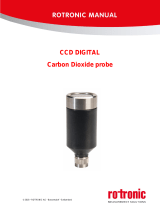
External Maintenance: By starting this action, maintenance services are possible, e.g. clean room cleaning
or calibration processes.
Calibration Back/Front Access: Calibration can either occur on the front or back inputs of the differential
pressure sensor – never set both calibration access points, front and back the same time.
There are 3 possibilities to access the differential pressure sensor of the CRP5 (see below).

D-M-CRP5-MODBUS-V1_03
Rotronic AG
Bassersdorf, Switzerland
Document code Unit
Modbus Manual V1.03:
CRP5 Clean Room Panel
Instruction Manual
Document Type
Page 8 of 42
Document title
© 2018- Rotronic AG Modbus CRP5V1.0_03
Front or Back Access
Fixed Front + Access
Fixed Front - Access

D-M-CRP5-MODBUS-V1_03
Rotronic AG
Bassersdorf, Switzerland
Document code Unit
Modbus Manual V1.03:
CRP5 Clean Room Panel
Instruction Manual
Document Type
Page 9 of 42
Document title
© 2018- Rotronic AG Modbus CRP5V1.0_03
2.2.4 Sensor Actions
Direct sensor actions!
Attention!
Be careful to use these commands, due to any possible miss adjustments.
Modbus command Write Multiple Coils (0x0F) is not possible.
Coils
Name
Type
Description
25
Differential Pressure Zero
Adjust
*
Zero adjust of the differential pressure sensor
These action takes about 15 seconds to execute
26
Differential Pressure Gain
Adjust
*!
Setting the gain of the differential pressure sensor
These action takes about 2 seconds to execute
27
Differential Pressure Reset
Adjustment
*
Resets differential pressure gain and offset settings to
1.0
(gain) and 0.0 (offset)
28 Acquire Humidity Data *!
Acquires a reference value for the humidity
It’s possible to acquire more than one different
reference values
29 Delete Acquired Humidity Data *
Deletes all acquired humidity reference values
30
Adjust Acquired Humidity Data *
The acquired humidity data will be sent to the
humidity sensor
Attention!
If no reference value
s
has acquired, humidity adjust is not
possible!
31 Adjust Temperature Data *!
The reference temperature data will be sent to the
temperature sensor
32 Reserved
Undefined
*
During these action, communication
with the device is not possible
!
Before activating these action, a reference value has to
be set for the desired sensor (s
ee
Reference
Value Settings
)
Note!
For adjustment procedures, you need a stable environment no matter what sensor will have adjusted.
Differential Pressure Gain Adjust: By starting this action, the differential pressure sensor will be adjusted
to a reference value that is applied to the chosen pressure inputs (front or back). This reference value must
be entered in the appropriate reference register (see Reference Value Settings -> Differential Pressure)
before the adjustment procedure is started. Beside the zero adjust point, only one further differential
pressure value can be acquired as a reference value.
Differential Pressure Reset Adjustment: The adjustment parameters determined during the production of
the CRP5 will be restored.
Acquire Humidity Data: By starting this action, the CRP5-probe will be adjusted to a reference humidity
value. This reference humidity in the unit of the applied reference must be entered in the appropriate
reference register (see Reference Value Settings -> Humidity) before the acquiring procedure is started. Up
to 99 humidity values can be acquired as reference values.
Delete Acquired Humidity Data: By starting this action, all acquired data will get lost.
Adjust Acquired Humidity Data: By starting this action, the CRP5-probe will be adjusted to the acquired
reference values. If no reference values has been acquired, a humidity adjustment is not possible.

D-M-CRP5-MODBUS-V1_03
Rotronic AG
Bassersdorf, Switzerland
Document code Unit
Modbus Manual V1.03:
CRP5 Clean Room Panel
Instruction Manual
Document Type
Page 10 of 42
Document title
© 2018- Rotronic AG Modbus CRP5V1.0_03
Adjust Temperature Data: By starting this action, the CRP5-probe will be adjusted to a reference
temperature value. This reference temperature in the unit of the applied reference must be entered in the
appropriate reference register (see Reference Value SettingsReference Value Settings -> Temperature)
before the adjust procedure is started. Only one temperature value can be acquired as a reference value.
2.2.5 Device Actions
Direct device actions!
Attention!
Be careful to use these commands, due to any possible wrong configurations.
Modbus command Write Multiple Coils (0x0F) is not possible.
Coils
Name
Type
Description
33 Reset Device *
Reset device
34 Store Device Settings *
Stores the actual settings of the device into FLASH
35 Restore All Device Settings *
Restores the device (factory) settings in FLASH to the
device
36
Restore Device Settings
without Ethernet Data
*
Restores the device (factory) settings in FLASH to the
device, without the Ethernet
settings
37 … 64 Reserved
Undefined
65 …
9’999
Reserved
Undefined
Gives back Modbus Exception Code 02
*
During these action, communication with the device is not possible
Reset Device: The device will be restarted.
Store Device Settings: All device-relevant data will be stored in the FLASH. Be careful, executing this
command, will overwrite older (factory) settings in the FLASH.
Restore All Device Settings: All device-relevant data will be restored from the FLASH to the device. Be
careful, all individual device settings by customer will be overwritten by the factory settings.
Restore All Device Settings without Ethernet Data: All device-relevant data, except Ethernet settings, will
have restored from the FLASH to the device. Be careful, all device settings will have overwritten, except the
Ethernet settings.

D-M-CRP5-MODBUS-V1_03
Rotronic AG
Bassersdorf, Switzerland
Document code Unit
Modbus Manual V1.03:
CRP5 Clean Room Panel
Instruction Manual
Document Type
Page 11 of 42
Document title
© 2018- Rotronic AG Modbus CRP5V1.0_03
2.2.6 Example: Read Single Coil
2.2.6.1 Red Relay 1 to 6
Initial situation: The relays 1, 3 and 5 are set.
RTU Example:
Transmit
01 01 00 00 00 07 7d c8
Receive
01 01 01 15 90 47
TCP Example:
Transmit
MBAP
01
0
1
00 00
00 0
7
Receive
MBAP 01 01 01 15
Field
Bytes
Value
Description
MBAP
7 MBAP
MBAP header (see Modbus RTU / TCP)
Checksum
2
CRC
CRC Checksum (
see
Modbus RTU / TCP
)
RTU number 1 0x01
Modbus RTU Address (RS485 Address + 1)
(see Device Descriptions)
Function code
1
0x01
Read
Single Coil
Starting address 2 0x0000
= 0, means address of the 1. coil
( Attention! coil number – 1 )
Quantity of coils 2 0x0007
= 7, 1 to 7 gives the same result 1 byte (8 coils)
8 to 15 will give back 2 bytes (16 coils) etc.
(maximal value for CRP5 0x003f = 63
≙
8 bytes)
Byte count 1 0x01
= 1
≙
N, means quantity of coils / 8, if the remainder
is different of 0 => N = N+1
Coil status
(see Relays)
n 0x15
n = N or N+1 = 8 bits
Bit State State of Relais 1 to 6
0 ON Coil 1 = Relais 1 (ON = 1, OFF = 0)
1 OFF Coil 2 = Relais 2 (ON = 1, OFF = 0)
2 ON Coil 3 = Relais 3 (ON = 1, OFF = 0)
3 OFF Coil 4 = Relais 4 (ON = 1, OFF = 0)
4 ON Coil 5 = Relais 5 (ON = 1, OFF = 0)
5 OFF Coil 6 = Relais 6 (ON = 1, OFF = 0)
6 OFF Not used
7 OFF Not use
For detailed information about Modbus protocol Read Single Coil see:
(http://modbus.org/docs/Modbus_Application_Protocol_V1_1b3.pdf).

D-M-CRP5-MODBUS-V1_03
Rotronic AG
Bassersdorf, Switzerland
Document code Unit
Modbus Manual V1.03:
CRP5 Clean Room Panel
Instruction Manual
Document Type
Page 12 of 42
Document title
© 2018- Rotronic AG Modbus CRP5V1.0_03
2.2.7 Example: Write Single Coil
2.2.7.1 Set State of Relay 2
RTU Example:
Transmit
01 05 00 01 ff 00 dd fa
Receive
01
0
5
00 01
ff 00
dd
fa
TCP Example:
Transmit
MBAP 01 05 00 01 ff 00
Receive
MBAP
01
0
5
00 01
ff 00
Field
Bytes
Value
Description
MBAP
7 MBAP
MBAP header (see Modbus RTU / TCP)
Checksum
2 CRC
CRC Checksum (see Modbus RTU / TCP)
RTU number 1 0x01
Modbus RTU Address (RS485 Address + 1)
(see Device Descriptions)
Function code 1 0x05 Write Single Coil
Starting address 2 0x0001
= 1, means address of the 2. coil
( Attention! coil number – 1 )
Output value 2 0xff00
0xff00 for setting the selected coil
0x0000 for resetting the selected coil
Test the change with Modbus commands in example Read coil 1 to coil 8
For detailed information about Modbus protocol Write Single Coil see:
(http://modbus.org/docs/Modbus_Application_Protocol_V1_1b3.pdf).
2.2.8 Example: Write Multiple Coils
2.2.8.1 Set State of Relay 1 to 6
RTU Example:
Transmit
01
0
f
00 00
00 0
7
01
2a
4f
49
Receive
01
0
f
00 00
00 0
7
14 09
TCP Example:
Transmit
MBAP 01 0f 00 00 00 07 01 2a
Receive
MBAP 01 0f 00 00 00 07
Field
Bytes
Value
Description
MBAP
7 MBAP
MBAP header (see Modbus RTU / TCP)
Checksum
2 CRC
CRC Checksum (see Modbus RTU / TCP)
RTU number 1 0x01
Modbus RTU Address (RS485 Address + 1)
(see Device Descriptions)
Function code 1 0x0f Write Multiple Coils
Starting address 2 0x0000
= 0, means address of the 1. coil
( Attention! coil number – 1 )
Quantity of outputs 2 0x0007 = 7 for coils 0 to 7

D-M-CRP5-MODBUS-V1_03
Rotronic AG
Bassersdorf, Switzerland
Document code Unit
Modbus Manual V1.03:
CRP5 Clean Room Panel
Instruction Manual
Document Type
Page 13 of 42
Document title
© 2018- Rotronic AG Modbus CRP5V1.0_03
Byte count 1 0x01
= 1
≙
N, means quantity of coils / 8, if the remainder
is different of 0
=>
N = N+1
Output values
(see Relays)
N * 1 0x2a
Bit State State of Relais 1 to 6
0
OFF
Coil 1 = Relais 1 (ON = 1, OFF = 0)
1
ON
Coil 2 = Relais 2 (ON = 1, OFF = 0)
2
OFF
Coil 3 = Relais 3 (ON = 1, OFF = 0)
3
ON
Coil 4 = Relais 4 (ON = 1, OFF = 0)
4
OFF
Coil 5 = Relais 5 (ON = 1, OFF = 0)
5
ON
Coil 6 = Relais 6 (ON = 1, OFF = 0)
6
OFF
Not used
7 OFF Not use
Test the change with Modbus commands in example Read coil 1 to coil 8
For detailed information about Modbus protocol Write Single Coil see:
(http://modbus.org/docs/Modbus_Application_Protocol_V1_1b3.pdf).
2.2.9 Example: Reset Device
RTU Example:
Transmit
01 05 00 20 ff 00 0d f0
Receive
01 05 00 20 ff 00 0d f0
TCP Example:
Transmit
MBAP 01 05 00 20 ff 00
Receive
MBAP 01 05 00 20 ff 00
Field
Bytes
Value
Description
MBAP
7 MBAP
MBAP header (see Modbus RTU / TCP)
Checksum
2 CRC
CRC Checksum (see Modbus RTU / TCP)
RTU number 1 0x01
Modbus RTU Address (RS485 Address + 1)
(see Device Descriptions)
Function code 1 0x05 Write Single Coil
Starting address 2 0x0020
= 32, means address of the 33. Coil (Reset Device)
( Attention! coil number – 1 )
Output value 2 0xff00 0xff00 for setting the selected action
For detailed information about Modbus protocol Write Single Coil see:
(http://modbus.org/docs/Modbus_Application_Protocol_V1_1b3.pdf).

D-M-CRP5-MODBUS-V1_03
Rotronic AG
Bassersdorf, Switzerland
Document code Unit
Modbus Manual V1.03:
CRP5 Clean Room Panel
Instruction Manual
Document Type
Page 14 of 42
Document title
© 2018- Rotronic AG Modbus CRP5V1.0_03
2.3 Device Specific Discrete Inputs (read only)
With Modbus Discrete Inputs you can get the state of the digital inputs of the CRP5.
Assisted Modbus command is Read Discrete Input (0x02).
2.3.1 Digital Inputs 1 and 2
Current state of the digital inputs of the CRP5, updated every measurement cycle, which means every
second.
Coil
Name
Type
Description
10’001 Digital Input
Bit
State of Initialization bits
0 Digital Input 1 (ON = 1, OFF = 0)
1
Digital Input 2 (ON = 1, OFF = 0)
2…15 0
10’002 …
10’063
Reserved
Undefined
10’064 …
29’999
Reserved
Gives back Modbus Exception Code 02
2.3.2 Example: Read Discrete Inputs
2.3.2.1 Read Modbus Coil 10'001
RTU Example:
Transmit
01
02
27 10
00 01
b2 bb
Receive
01
02
01
01
60 48
TCP Example:
Transmit
MBAP
01
02
27 10
00 01
Receive
MBAP 01 02 01 01
Field
Bytes
Value
Description
MBAP
7 MBAP
MBAP header (see Modbus RTU / TCP)
Checksum
2
CRC
CRC Checksum
(
see
Modbus RTU / TCP
)
RTU number 1 0x01
Modbus RTU Address (RS485 Address + 1)
(see Device Descriptions)
Function code
1
0x02
Read Discret Inputs
Starting address 2 0x2710 = 10'000 ( Attention! coil number – 1 )
Quantity of inputs 2 0x0001 = 1, means read 1 byte (8 bits)
Byte count 1 0x01 = 1
≙
N
, means numbers of returned bytes
Input status
(see Digital Inputs)
N * 1 0x01
Bit State of Digital Inputs
0 Digital Input 1 (ON = 1, OFF = 0)
1 Digital Input 2 (ON = 1, OFF = 0)
2…7 not used
For detailed information about Modbus protocol Read Discrete Inputs see:
(http://modbus.org/docs/Modbus_Application_Protocol_V1_1b3.pdf).

D-M-CRP5-MODBUS-V1_03
Rotronic AG
Bassersdorf, Switzerland
Document code Unit
Modbus Manual V1.03:
CRP5 Clean Room Panel
Instruction Manual
Document Type
Page 15 of 42
Document title
© 2018- Rotronic AG Modbus CRP5V1.0_03
2.4 Device Specific Input Registers (read only)
With Modbus Input Registers you can read some device specific data of the CRP5.
Assisted Modbus command is Read Input Registers (0x04).
2.4.1 Device Data
CRP5-specific data.
Register
Name
Type
Description
30’001
Serial Number
&
Serial number of the device (part 1)
30’002 &
Serial number of the device (part 2)
30’003
Serial Number Probe
&
Serial number of the
CRP5
-
probe (part 1)
30’004 &
Serial number of the
CRP5
-
probe (part 2)
30’005
Device Name
Device name (part 1 – character 1 & 2) e.g. “CR”
30’006
Device name (part 2
–
character 3
& 4)
e.g.
“P
-
“
30’007
Device name (part 3
–
character 5 & 6)
e.g.
“1 “
30’008
Device name (part 4 – character 7 & 8) e.g. “ab“
30’009
Device name (part 5
–
character 9 & 10)
e.g. “cd
“
30’010
Device name (part 6 – character 11 & 12) e.g. “ef“
30’011
Differential Pressure Sensor
Type
No. Differential pressure sensor type
0
±
10Pa
1
± 25Pa
2
± 50Pa
3 ± 100Pa
4
± 250Pa
5
± 500Pa
6
± 50Pa (
Second source supplier
)
7
± 100Pa (
Second source supplier
)
8
± 250Pa (
Second source supplier
)
30’012 Hardware Version
H
ardware v
ersion
30’013
Production Date
&!
Production date (part 1)
30’014 &!
Production date (part 2)
30’015 Reserved
U
ndefined
30’016 Reserved
U
ndefined
30’017 State of Reset
Internal use only
30’018 State of Initialization
Internal use only
30’019 State of Alarms
Bit
State of
A
larm b
its
0
Alarm Differential Pressure Hi
1
Alarm Differential Pressure Low
2 Alarm Humidity Hi
3
Alarm Humidity Low
4 Alarm Temperature Hi
5
Alarm Temperature Low
6
Alarm
Calculation Hi
7
Alarm Calculation Low
8 Alarm Analog Input 1 Hi
9 Alarm Analog Input 1 Low
10
Alarm Analog Input 2 Hi

D-M-CRP5-MODBUS-V1_03
Rotronic AG
Bassersdorf, Switzerland
Document code Unit
Modbus Manual V1.03:
CRP5 Clean Room Panel
Instruction Manual
Document Type
Page 16 of 42
Document title
© 2018- Rotronic AG Modbus CRP5V1.0_03
11
Alarm Analog Input 2 Low
12 Alarm Digital Input 1
13
Alarm Digital Input 2
14…15 0
0 = alarm OFF; 1 = a
larm O
N
30’020 State of Other Alarms
Bit
State
of
O
ther
A
larm b
its
0
Internal use only
1
Internal use only
2…7 0
8
Missing Probe Maintenance
9
Internal Maintenance
10
External Maintenance
11 Calibration Back Access
12
Calibration Front Access
13
…15
0
0 = alarm OFF; 1 = alarm ON
30’021 State of Relays and Valve
Bit
State
of
Relay/Valve
b
its
0
Relay 1
1
Relay 2
2 Relay 3
3
Relay 4
4
Relay 5
5
Relay 6
6
…7
0
8
Valve A
9
Valve B
10 Valve C
11
Valve D
12
…15
0
0 = deactivated; 1 = activated
30’022 …
30’500
Reserved
Undefined
Gives back Modbus Exception Code 02
&
These are 32-bit values, separated in two succeeding registers (16-bits). How to bring together part 1
and part 2 of the 32-bit value, depends on the Swap Mode of the Modbus communication (see
Device Settings
-
>
Modbus
Operation
Mode
and
Selectable Swap Modes for Rotronic Devices
)
“ Character values separated in succeeding registers, e.g. “CRP5-1 abcdef”
!
Represents
the Unix Time (UTC) since 1.1.1970 in seconds
State of Alarms: Shows all possible sensor alarms. You have to enable the appropriate alarm bit and alarm
level (see “Holding Registers” -> “Alarm Settings” -> “Alarm Bits” resp. “Sensors”) before an alarm can be
activated.
State of Other Alarms: Shows all possible “other” alarms, like maintenance modes, calibration access and
differential pressure offset limits.
State of Relays and Valves: Shows the current state of the relays and valves.
2.4.2 Current Values: Float Values
Current values in 32-bit IEEE754 float format of all CRP5 sensors, updated every measurement cycle (see
“Holding Registers” -> “Device Settings” -> “Measurement Interval”).

D-M-CRP5-MODBUS-V1_03
Rotronic AG
Bassersdorf, Switzerland
Document code Unit
Modbus Manual V1.03:
CRP5 Clean Room Panel
Instruction Manual
Document Type
Page 17 of 42
Document title
© 2018- Rotronic AG Modbus CRP5V1.0_03
Note!
These values are changing every measurement cycle, so always read the two corresponding registers in
one Modbus command.
The transmitted values are always in the basic unit of the measurement.
Register
Name
Type
Description
31’001
Humidity [%rh]
&
Current
humidity value (part 1)
31’002 &
Current humidity value (part 2)
31’003
Temperature [°C]
&
Current
temperature
value (part 1)
31’004 &
Current
temperature
v
alue (part 2)
31’005
Differential Pressure [Pa]
&
Current differential pressure value (part 1)
31’006 &
Current
differential pressure
v
alue (part 2)
31’007
Calculation [basic unit]
(Unit depends on calculation)
&
Current
calculation
value (part 1)
31’008 &
Current calculation value (part 2)
31’009
Analog Input 1 [selected unit]
&
Current
analog input 1
value (part 1)
31’010 &
Current analog input 1 value (part 2)
31’011
Analog Input 2 [selected unit]
&
Current analog input 2 value (part 1)
31’012 &
Current
analog input 2
value (part 2)
31’013
Digital Input 1
&
Current digital input 1 value (part 1)
31’014 &
Current digital input 1 value (part 2)
31’015
Digital Input 2
&
Current
digital input 2
value (part 1)
31’016 &
Current digital input 2 value (part 2)
31’017
Ambient Pressure [hPa]
&
Current ambient pressure value (part 1)
31’018 &
Current
ambient pressure
value (part 2)
31’019
Internal Temperature
&
Current internal temperature value (part 1)
31’020 &
Current internal temperature value (part 2)
31’021 …
31’999
Reserved
Undefined
Gives back Modbus Exception Code 02
&
These are float
-
values (32
-
bit
IEEE754)
,
separated
in two succeeding registers (16
-
bits).
How to bring together part 1 and part 2 of the 32-bit float-value, depends on the Swap Mode of the
Modbus communication (see Device SettingsDevice Settings -> Modbus Operation Mode and
Selectable Swap Modes for Rotronic Devices
)
2.4.3 Current Values: Integer Values
Current values in 16-bit integer format of all CRP5 sensors, updated every measurement cycle, which
means all every second.
The current values are the result of the reduction to 16-bit values of the multiplication of the current 32-bit
IEEE754 float values (see Current Values: Float Values) and the corresponding scaling values (see Integer
Value Scaling).
Note!
The transmitted values are always in the basic unit of the measurement.
Register
Name
Type
Description
32’001 Humidity [%rh]
Current humidity v
alue
32’002 Temperature [°C]
Current temperature value
32’003 Differential Pressure [Pa]
Current differential pressure value
32’004
Calculation
[basic unit]
(Unit depends on calculation)
Current calculation value

D-M-CRP5-MODBUS-V1_03
Rotronic AG
Bassersdorf, Switzerland
Document code Unit
Modbus Manual V1.03:
CRP5 Clean Room Panel
Instruction Manual
Document Type
Page 18 of 42
Document title
© 2018- Rotronic AG Modbus CRP5V1.0_03
32’005 Analog Input 1 [selected unit]
Current
analog i
nput 1
v
alue
32’006 Analog Input 2 [selected unit]
Current analog input 2 value
32’007 Digital Input 1
Current
digital i
nput 1
v
alue
32’008 Digital Input 2
Current
digital i
nput 2
v
alue
32’009 Ambient Pressure [hPa]
Current ambient pressure value
32’010 Internal Temperature [°C]
Current
internal t
emperature
v
alue
32’011 …
32’999
Reserved
Undefined
Gives back Modbus Exception Code 02
2.4.4 FDA Data
FDA Data fields contain information about firmware update, sensor adjustments and device properties.
Register
Name
Type
Description
33’001
FDA Date FW Update
&!
FDA
d
ate
firmware u
pdate (part 1)
33’002 &!
FDA date firmware update (part 2)
33’003
FDA ID FW Update
&
FDA ID firmware update (part 1)
33’004 &
FDA ID firmware update (part 2)
33’005
FDA Date DiffP. Adjust (RAG)
&!
DA date differential pressure adjust RAG (part 1)
33’006 &!
DA
date
differential pressure adjust RAG (part 2)
33’007
FDA ID DiffP. Adjust (RAG)
&
FDA ID
differential pressure
adjust RAG (part 1)
33’008 &
FDA ID differential pressure adjust RAG (part 2)
33’009
FDA Date DiffP. Adjust (User)
&!
FDA
date
differential pressure adjust user (part 1)
33’010 &!
FDA
date
differential pressure adjust user (part 2)
33’011
FDA ID DiffP. Adjust (User)
&
FDA ID differential pressure adjust user (part 1)
33’012 &
FDA ID
differential pressure
adjust user (part 2)
33’013
FDA Date Properties
&!
FDA date device properties (part
1)
33’014 &!
FDA date device properties (part 2)
33’015
FDA ID Properties
&
FDA ID device properties (part 1)
33’016 &
FDA ID device properties (part 2)
33’017 …
33’999
Reserved
Undefined
Gives back Modbus Exception Code 02
&
These are 32-bit values, separated in two succeeding registers (16-bits). How to bring together part 1
and part 2 of the 32-bit value, depends on the Swap Mode of the Modbus communication (see
Device SettingsDevice Settings -> Modbus Operation Mode and Selectable Swap Modes for
Rotronic Devices)
!
Represents the Unix Time (UTC) since 1.1.1970 in seconds
FDA Date DiffP. Adjust (User):
FDA ID DiffP. Adjust (User):
FDA Date Properties:
FDA ID Properties:
If you change the device properties or set the offset/gain of the differential pressure over the menu of the
CRP5 or Modbus, the date and ID of the FDA-fields Diffp. Adjust (User) and Properties would be changed.
Date
ID
Change in the CRP5-menu 0, representing 1.1.1970 Serial Number of the CRP5
Change over Modbus 0, representing 1.1.1970 0xFFFFFFFF

D-M-CRP5-MODBUS-V1_03
Rotronic AG
Bassersdorf, Switzerland
Document code Unit
Modbus Manual V1.03:
CRP5 Clean Room Panel
Instruction Manual
Document Type
Page 19 of 42
Document title
© 2018- Rotronic AG Modbus CRP5V1.0_03
2.4.5 Example: Read Input Register
2.4.5.1 Read Current Values: Float Value (Registers 31'001 to 31'006)
RTU Example:
Transmit
01
0
4
7
9
18
00 0
6
e9
53
Receive
01 04 0c 41 f3 70 a3 41 ba 00 00 3d 80 e9 a2 97 8a
TCP Example:
Transmit
MBAP 01 04 79 18 00 06
Receive
MBAP 01 04 0c 41 f3 70 a3 41 ba 00 00 3d 80 e9 a2
Field
Bytes
Value
Description
MBAP
7 MBAP
MBAP header (see Modbus RTU / TCP)
Checksum
2 CRC
CRC Checksum (see Modbus RTU / TCP)
RTU number 1 0x01
Modbus RTU Address (RS485 Address + 1)
(see Device Descriptions)
Function code 1 0x04 Read Discret Inputs
Starting address 2 0x7918 = 31'000 ( Attention! register number – 1 )
Quantity of input
registers
2
0x000
6
=
6
, means read
6 registers
Byte count 1 0x0c = 12
≙
2 *
N
, means numbers of returned bytes
Input registers
(see Current Values: Float
Values)
2 * N
0x41f370a3 = 30.43 %rh Humidity
0x41ba0000
=
23.25
°C Temperature
0x3d80e9a2 = 0.063 Pa Differential Pressure
For detailed information about Modbus protocol Read Discrete Inputs see:
(http://modbus.org/docs/Modbus_Application_Protocol_V1_1b3.pdf).
2.5 Device Specific Holding Registers
With Modbus Holding Registers you can read and write device specific data to the CRP5.
Assisted Modbus commands are Read Holding Registers (0x03), Write Single Register (0x06) and Write
Multiple Registers (0x10).
Attention!
Changes to register content in the CRP5 can change the functionality of the CRP5. This may cause the
CRP5 to become inoperable.
Changes of register contents should only be made with the necessary knowledge of the Modbus protocol.
2.5.1 Value Type
Selection of the possible calculation and analog input modes.
Register
Name
Type
Description
40’001 Calculation Type !
No.
Select
Calculation
0
Dew Point
1
Frost Point
2
Wet Bulb Temperature
3
Enthalpy
4 Vapour Concentration
5
Specific Humidity

D-M-CRP5-MODBUS-V1_03
Rotronic AG
Bassersdorf, Switzerland
Document code Unit
Modbus Manual V1.03:
CRP5 Clean Room Panel
Instruction Manual
Document Type
Page 20 of 42
Document title
© 2018- Rotronic AG Modbus CRP5V1.0_03
6
Mixing Ratio
7 Saturation Vapour Concentration
8
Vapour Partial Pressure
9 Vapour Saturation Pressure
40’002 Analog Input 1 Type !
No.
Description of the
Analog
Input 1 type
0
Voltage Input
1 Current Input (120Ω)
40’002 Analog Input 2 Type !
No.
Description of the Analog Input 2 type
0
Voltage Input
1 Current Input (120Ω)
40’003 …
40’099
Reserved
Undefined
Gives back Modbus Exception Code 02
! Change of these registers needs a restart of the device (see Device Actions)
Calculation Type: Select the calculation showed on display (row 4), if selected (see Display Settings ->
Display Row 4).
Analog Input x Type: Select the analog input type, voltage or current (120Ω internal resistance).
/