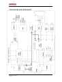
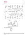
Akira 21SWP1/CE is a 21-inch color television with a variety of features that make it a great choice for any home. It has a multi-system voltage synthesis that allows it to be used in a variety of countries, and it supports multiple color systems including PAL, SECAM, and NTSC. The television also has a variety of input and output options, including two AV inputs and one AV stereo output. This makes it easy to connect your DVD player, game console, or other devices to the television.
Akira 21SWP1/CE is a 21-inch color television with a variety of features that make it a great choice for any home. It has a multi-system voltage synthesis that allows it to be used in a variety of countries, and it supports multiple color systems including PAL, SECAM, and NTSC. The television also has a variety of input and output options, including two AV inputs and one AV stereo output. This makes it easy to connect your DVD player, game console, or other devices to the television.


-
 1
1
-
 2
2
-
 3
3
-
 4
4
-
 5
5
-
 6
6
-
 7
7
-
 8
8
-
 9
9
-
 10
10
-
 11
11
-
 12
12
-
 13
13
-
 14
14
-
 15
15
-
 16
16
-
 17
17
-
 18
18


Akira 21SWP1/CE is a 21-inch color television with a variety of features that make it a great choice for any home. It has a multi-system voltage synthesis that allows it to be used in a variety of countries, and it supports multiple color systems including PAL, SECAM, and NTSC. The television also has a variety of input and output options, including two AV inputs and one AV stereo output. This makes it easy to connect your DVD player, game console, or other devices to the television.
Ask a question and I''ll find the answer in the document
Finding information in a document is now easier with AI
Related papers
Other documents
-
Sanyo 14GX37 User manual
-
Haier HLH326BB - 32" LCD TV User manual
-
-
-
TEAC EU-34T User manual
-
Polaroid Polaview 211 User manual
-
 Ernest Sports ES12 User manual
-
Apex Digital AT2008S User manual
-
Bizerba ES10 Operating Instructions Manual
-
MARK-10 ES20 User guide
