Page is loading ...

I N I
TOOLS'n TASKS
TM/MC
26-.GALLON OIL-FREE
AiR COMPRESSOR
Model: 15560
S
218549
TOLL FREE HELPLINE: 1=888=266-7096
FOR SAFE OPERATION, READ AND UNDERSTAND
ALL CONTENTS OF THE iNSTRUCTiON MANUAL

SAVE THiS MANUAL
Keep this manual for the safety warnings and precautions, assembly, operating,
inspection, maintenance and cleaning procedures. Write the product's serial number in
the back of the manual near the assembly diagram (or month and year of purchase if
product has no number). Keep this manual and the receipt in a safe and dry place for
future reference.
IMPORTANT SAFETY INFORMATION
in this manual, on the labeling, and all other information
provided with this product:
This is the safety alert symbol, it is used to alert you to potential
personal injury hazards. Obey all safety messages that follow this
symbol to avoid possible injury or death.
DANGER indicates a hazardous situation
which, if not avoided, will result in death or
serious injury.
WARNING indicates a hazardous situation
which, if not avoided, could result in death
or serious injury.
CAUTION, used with the safety alert
symbol, indicates a hazardous situation
which, if not avoided, could result in minor
or moderate injury.
NOTICE is used to address practices not
related to personal injury.
CAUTION, without the safety alert symbol,
is used to address practices not related to
personal injury.
Page 2

,
.
GENERAL SAFETY RULES
WARNING! Read all instructions
Failure to follow all instructions listed below may result in electric shock,
fire, and/or serious injury. The term "power tool" in all of the warnings listed
below refers to your mains-operated (corded) power tool.
Work area safety
a. Keep work area clean and well lit. Cluttered or dark areas invite accidents.
b. Do not operate power tools in explosive atmospheres, such as in the
presence of flammable liquids, gases or dust. Power tools create sparks
which may ignite the dust or fumes.
c. Keep children and bystanders away while operating a power tool.
Distractions can cause you to lose control.
_ i_ To reduce the risk of electric shock or injury, use indoors only.
Electrical safety
a.
Power tool plugs must match the outlet. Never modify the plug in any
way. Do not use any adapter plugs with earthed (grounded) power tools.
Unmodified plugs and matching outlets will reduce risk of electric shock.
b.
Avoid body contact with earthed or grounded surfaces such as pipes,
radiators, ranges and refrigerators. There is an increased risk of electric
shock if your body is earthed or grounded.
c. Do not expose power tools to rain or wet conditions. Water entering a
power tool will increase the risk of electric shock.
d.
Do not abuse the cord. Never use the cord for carrying, pulling or
unplugging the power tool. Keep cord away from heat, oil, sharp edges
or moving parts. Damaged or entangled cords increase the risk of electric
shock.
Personal safety
a.
Stay alert, watch what you are doing and use common sense when operating
a power tool. Do not use a power too! while you are tired or under the
influence of drugs, alcohol or medication. A moment of inattention while
operating power tools may result in serious personal injury.
b.
Use safety equipment. Always wear eye protection. Safety equipment
such as dust mask, non-skid safety shoes, hard hat, or hearing protection
used for appropriate conditions will reduce personal injuries.
C.
Avoid accidental starting. Ensure the switch is in the off=position before
plugging in. Carrying power tools with your finger on the switch or plugging in
power tools that have the switch on invites accidents.
Page 3

.
.
d.
e.
f.
Remove any adjusting key or wrench before turning the power tool on. A
wrench or a key left attached to a rotating part of the power tool may result in
personal injury.
Do not overreach. Keep proper footing and balance at all times. This
enables better control of the power tool in unexpected situations.
Dress properly. Do not wear loose clothing or jewellery. Keep your hair,
clothing and gloves away from moving parts. Loose clothes, jewellery or long
hair can be caught in moving parts.
Power tool use and care
a.
b.
c.
d.
e.
f.
Do not force the power tool. Use the correct power tool for your application.
The correct power tool will do the job better and safer at the rate for which it
was designed.
Do not use the power tool if the switch does not turn it on and off. Any power
tool that cannot be controlled with the switch is dangerous and must be
repaired.
Disconnect the plug from the power source before making any
adjustments, changing accessories, or storing power tools, Such
preventive safety measures reduce the risk of starting the power tool
accidentally.
Store idle power tools out of the reach of children and do not allow
people unfamiliar with the power tool or these instructions to operate
the power tool. Power tools are dangerous in the hands of untrained users.
Maintain power tools. Check for misalignment or binding of moving parts,
breakage of parts and any other condition that may affect the power tools
operation. If damaged, have the power tool repaired before use. Many
accidents are caused by poorly maintained power tools.
Use the power too! in accordance with these instructions and in the manner
intended for the particular type of power tool, taking into account the working
conditions and the work to be performed. Use of the power tool for operations
different from those intended could result in a hazardous situation.
Service
a. Have your power tool serviced by a qualified repair person using only
identical replacement parts. This will ensure that the safety of the power tool
is maintained.
,
SPECIFIC SAFETY RULES
Maintain labels and nameplates on the Air Compressor. These carry important
safety information. If unreadable or missing, contact TOLL FREE HELPLINE
1-888-266-7096.
Page 4

,
,
,
,
,
7.
,
,
10.
11.
CAUTION: Your Warranty is voided if you drop the Air Compressor. Always
transport the Air Compressor using its Handle and Wheels.
DANGER! This Air Compressor is NOT equipped and should not be used "as-is"
to supply breathing air. For any application of air for human consumption, you
must fit the Air Compressor with suitable in-line safety and alarm equipment (not
included). This additional equipment is necessary to properly filter and purify
the air to meet minimal specifications for Grade D breathing as described in
Compressed Gas Association Commodity Specification G 7.1-1966, OSHA 29
CFR 1910. 134, and/or Canadian Standards Associations (CSA). In the event
the Air Compressor is used for the purpose of breathing air application and
proper in-line safety and alarm equipment is not simultaneously used, existing
warranties are void, and supplier and manufacturer disclaims any liability
whatsoever for any loss, personal injury, or damage.
DANGER! Never attempt to repair or modify the Air Tank (27). Welding, drilling,
or any other modification will weaken the Tank resulting in damage from rupture
or explosion. Always replace worn, cracked, or damaged Tanks.
WARNING! Never use plastic (PVC) pipe for compressed air; serious injury or
death could result. Any tube, pipe, or hose used must have a pressure rating
higher than 155 PSI. Minimum recommended pipe size: Up to 50 feet long use
1/2" diameter. Greater than 50 feet use 3/4" diameter. Larger diameter pipe is
always better.
CAUTION: DO NOT use an extension cord with this product.
Make sure all tools and equipment used with the Air Compressor are rated to the
appropriate capacity. Do not use any tool or equipment that operates over 155
PSI.
Drain the Air Compressor every day. Do not allow excessive moisture to build up
inside the Air Compressor's Tank. Do not open the Drain Valve (30) with more
than !0 PSI of air pressure in the Tank. Do not unscrew the Drain Valve so that
more than four turns are showing.
Avoid injury. Never direct the Air Outlet Valve (8) at people or animals.
Do not alter or remove the Safety Release Valve (18).
Make sure the Air Compressor is located on a flat, level, sturdy surface capable
of supporting the weight of the Compressor, operator(s), and any additional tools
and equipment.
Do not move or transport the Compressor if the Air Tank (27) is under pressure.
Industrial applications must follow OSHA guidelines.
Page 5

14.
15.
16.
17.
18.
19.
20.
Never stand on the Air Compressor. Serious injury could result if the Compressor
is tipped.
Never leavetheAir Compressor unattendedwhen it is plugged in and running.
Turn off the Compressor,and unplug the unit before leaving.
Do not allowchildren and other unauthorized people to handle or playwith the Air
Compressor.
Do not modifythe factory set pressure shutoff or startup switches. This tool will
do thework betterand safer at the speed and capacity for which it was designed.
Avoid body contact with oils and lubricants used in the Compressor. If
swallowed, seek medicaltreatment immediately. For skin contact, immediately
wash with soap and water. For eye contact, immediately flush eyes with clean
water.
WARNING: The brass components of this product contain lead, a chemical
known to the State of California to cause birth defects (or other reproductive
harm). (California Health & Safety code § 25249.5, et seq.)
WARNING: The warnings and precautions discussed in this manual cannot
cover all possible conditions and situations that may occur. It must be
understood by the operator that common sense and caution are factors which
cannot be built into this product, but must be supplied by the operator.
GROUNDING iNSTRUCTIONS
This product must be grounded. In the event of a malfunction or breakdown,
grounding provides a path of least resistance for electric current to reduce the risk
of electric shock.
This product is equipped with an electric cord having an equipment=grounding
conductor and a grounding plug. The plug must be plugged into a matching
outlet that is properly installed and grounded in accordance with all local codes
and ordinances.
Do not modify the plug provided. If it will not fit the outlet, have the proper outlet
installed by a qualified electrician.
WARNING:
Improper installation of the grounding plug is liable to result in a risk of electric
shock. When repair or replacement of the cord is required, do not connect the
grounding wire to either flat blade terminal. The wire with insulation having an
outer surface that is green with or without yellow stripes is the grounding wire.
Page 6

GROUNDING iNSTRUCTiONS
Check with a qualified electrician or service personnel if the grounding
instructions are not completely understood, or if in doubt as to whether the
product is properly grounded.
Repair or replace a damaged or worn cord immediately. This product is for use
on a nominal t20 V circuit and has a grounding plug similar to the plug illustrated
in figure.Only connect the product to an outlet having the same configuration as
the plug. Do not use an adapter with this product.
Plug
Grounding pin
@
® \
@
Grounded
Outlets
3-Prong Plug and Outlet
Page 7

SPECiFiCATiONS
Electrical Requirements
Compressor Type
Maximum Air Pressure 155 PSI
Air Delivery 3.4 SCFM @ 90 PSI / 4.0 SCFM @ 40 PSI
Air Tank Capacity 26 Gallons
Female Air Outlet Size 1/4"-18 NPT
Automatic
125 PSI Automatic Turn-On
Turn=On/Shut-Off
155 PSI Automatic Shut-Off (+ or - 5 PSI)
Pressure
Additional Features Built-In Tool Storage Compartment
Overall Dimensions 43-7/8" H x 17-3/4" W x 21-1/4" L (Up to Handle)
Net Weight 86 Ibs.(39kg)
UNPACKING
120 V~ / 60 Hz / 13A
4.0 HP Motor (Peak) / 1500 Watts (Running) / 13000 Motor RPM
Motor Thermal Protection Shut-Off: 275 Degrees Fahrenheit
Thermal Protection Reset: Present (18 Amp Circuit Breaker Used)
Power Cord: 16 AWG x 3C / 6' Long
Power Plug: 3-Prong / Grounded
Oilless for Maintenance Free Operation
When unpacking, check to make sure that the item is intact and undamaged. If
any parts are missing or broken, please call TOLL FREE HELPLINE at the number shown
on the cover of this manual as soon as possible.
SET UP iNSTRUCTIONS
Read the ENTIRE IMPORTANT SAFETY INFORMATION section at the
beginning of this manual including all text under subheadings therein
before set up or use of this product.
Risk of accidental starting; resulting in serious personal
injury. Turn the Power Switch of the tool to its "OFF"
position and unplug the tool from its electrical outlet before
assembling or making any adjustments to the tool.
Note: For additional information regarding the parts listed in the following pages, refer
to the Assembly Diagram near the end of this manual.
Assembly
,
CAUTION! Always make sure the Air Compressor's Power Switch (2) is in its
"OFF" position prior to performing any service, maintenance, or cleaning of the
Compressor.
Page 8

,
To extend the life of your tools and equipment, it is recommended that you
install an oiler and water filter in-line with the Air Outlet Valve (8) of the Air
Compressor, (See Figure A)
REGULATOR
FIGURE A I
Tool _!_ /_;1
%:-......._Y,_" I I
OILER WATER
FILTER
AIR
COMPRESSOR
SAFETY VALVE (18)
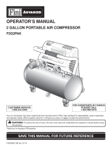
PRODUCT FEATURES
TOP VIEW
POWER SWITCH (2)
PROTECTOR
(3)
TANK
AIR PRESSURE
120)
PRESSURE GAUGE
(19)
QUICK CONNECTOR
(24)
FIGURE B
REGULATOR (17)
OPERATING INSTRUCTIONS
Read the ENTIRE IMPORTANT SAFETY INFORMATION section at the
beginning of this manual including all text under subheadings therein
before set up or use of this product.
Page 9

GENERAL OPERATING INSTRUCTIONS
,
.
Pull on the Safety Valve (18) to make sure it moves freely.
(See Figure B, previous page)
Check to make sure the Air Tank's Drain Valve (30), located at the bottom of the
Air Tank (27), is fully closed. (See Figure C)
AIR TANK (27)
FIGURE C
(30)
.
.
5.
6.
.
.
g.
If the recommended water filter/regulator/oiler setup is implemented. (Figure A)
Connect the air hose (not included) to the oiler outlet. Then connect the other
end of the air hose to the pneumatic tool (not included) being used.
(See Figure B)
Plug the Power Cord (16) into the nearest 120 volt, grounded, electrical outlet.
Turn the Power Switch (2) to its "ON" position to start the unit. (See Figure B)
When the Tank Air Pressure Gauge (20) reaches at least 125 PSI, turn the air
Regulator (17) clockwise or counterclockwise to allow the proper amount of air
flow to reach the pneumatic tool being used. (See Figure B)
NOTE: The Regulator adjusts as follows:
. Clockwise to increase tool air pressure.
. Counterclockwise to decrease tool air pressure.
IMPORTANT: When the maximum air pressure, 155 PSI, is reached as
indicated by the Tank Air Pressure Gauge (20), the Motor will stop. The Air
Compressor will automatically restart when the air pressure drops below 125
PSI.
IMPORTANT: The internal overload protection mechanism will automatically
shut off the Motor if the Motor becomes too hot. In this case, turn the Power
Page 10

10.
11.
12.
13.
Switch to its "OFF" position. Wait until the Motorcools. Pressthe Overload
Protector (3) button. Then restart theAir Compressor.
Tostop theAir Compressor,turn the Power Switch (2)to its "OFF" position.
Then unplug the Compressor from its electrical outlet. (See Figure B)
Pull the Safety Valve (18) to release any remaining air pressure from the Air Tank
(27). Next, squeeze the trigger on the pneumatic tool to release any remaining
air pressure from the tool. Then, disconnect the air hose from the Air Outlet
Valve (8). (See Figure B)
Remove any moisture from the Air Tank (17) by opening the Drain Valve (30).
Then, retighten the Drain Valve. (See Figure B)
Allow the Air Compressor to completely cool. Then store the Compressor in a
clean, dry, safe location out of reach of children and other unauthorized people.
MAINTENANCE AND SERVICING
Risk of serious personal injury from accidental starting
or electric shock. Turn the Power Switch of the tool to its
"OFF" position and unplug the tool from its electrical outlet
before performing any inspection, maintenance, or cleaning
procedures.
Damaged equipment can fail, causing serious personal
injury. Do not use damaged equipment, if abnormal noise or
vibration occurs, have the problem corrected before further
use.
,
.
.
.
.
Ins ection Maintenance And Cleanin
BEFORE EACH USE, inspect the general condition of the Air Compressor.
Check for loose screws, misalignment or binding of moving parts, cracked or
broken parts, damaged electrical wiring, and any other condition that may affect
its safe operation.
AFTER EACH USE, remove any moisture from the Air Tank (27) by opening the
Drain Valve (30). Then, retighten the Drain Valve. (See Figure B)
AFTER EACH USE, clean the external surfaces of the Air Compressor with a
clean, moist cloth. Then dry. Do not use solvents. Do not introduce water into
the electrical components of the Air Compressor.
WARNING! If the supply cord of this power tool is damaged, it must be replaced
only by a qualified service technician.
CAUTION! All maintenance, service, and repairs not mentioned in this manual
must only be performed by a qualified service technician.
Page 11

TROUBLESHOOTING
Possible CausesProblem
Air Compressor will
not start,
Low air pressure to
pneumatic tool.
Air pressure too high
to pneumatic tool.
Power Switch not
operating properly.
1. No power at outlet.
2. Cord not connected.
3. Air Tank maximum air pressure
of 155 PSI has been reached.
Compressor Motor will
automatically shut-off.
1. Compressor Regulator not properly
adjusted.
1. Compressor Regulator not properly
adjusted.
1. Damaged Power Switch.
,
2.
3.
Probable Solutions
Check power at outlet.
Check that cord is plugged in.
Wait until Air Tank air pressure falls
to 125 PSI. Compressor Motor will
then automatically turn on.
1. Turn Regulator clockwise to
increase air flow to pneumatic tool.
1. Turn Regulator counterclockwise to
decrease air flow to pneumatic tool.
1. Immediately disconnect Power
Cord from its electrical outlet.
Do not use Compressor until a
qualified service technician repairs
Power Switch.
PLEASE READ THE FOLLOWING CAREFULLY
THE MANUFACTURER AND/OR DISTRIBUTOR HAS PROVIDED THE PARTS LIST AND ASSEMBLY
DIAGRAM IN THIS MANUAL AS A REFERENCE TOOL ONLY. NEITHER THE MANUFACTURER OR
DISTRIBUTOR MAKES ANY REPRESENTATION OR WARRANTY OF ANY KIND TO THE BUYER THAT
HE OR SHE IS QUALIFIED TO MAKE ANY REPAIRS TO THE PRODUCT, OR THAT HE OR SHE IS
QUALIFIED TO REPLACE ANY PARTS OF THE PRODUCT. IN FACT, THE MANUFACTURER AND/OR
DISTRIBUTOR EXPRESSLY STATES THAT ALL REPAIRS AND PARTS REPLACEMENTS SHOULD BE
UNDERTAKEN BY CERTIFIED AND LICENSED TECHNICIANS, AND NOT BY THE BUYER. THE BUYER
ASSUMES ALL RISK AND LIABILITY ARISING OUT OF HIS OR HER REPAIRS TO THE ORIGINAL
PRODUCT OR REPLACEMENT PARTS THERETO, OR ARISING OUT OF HIS OR HER INSTALLATION
OF REPLACEMENT PARTS THERETO.
Page 12

PARTS LiST
Part No. Description Q'ty
1 3220404 Screw 6
2 3630283-1 Power Switch 1
3 3630183-1 Overload Protector 1
4 3410483 Tool Box Cover 1
5 3410183-2 Upper Cover 1
6 3110551 Motor Assy 1
7 3390183-1 Steel Wire Tube 1
8 3190551-1 Air Outlet Valve 1
9 3790651-2 Copper Tube 1
10 3630383 Pressure Controller 2
11 3221951-1 Screw 3
12 3290806 Washer 3
13 3420251-2 Bracket Support 3
14 3410283 Cover (Bottom) 1
15 3220106 Screw 2
16 3640183 Power Cord 1
17 31103119 Regulator turncap 1
18 3390853 Safety Valve 1
Part No. Description Q'ty
19 3290283-1 Output Air Pressure Gauge 1
20 3290183-1 Tank Air Pressure Gauge 1
21 3411535 Wire clip 1
22 3330283 Handle 1
23 3110283-1 Pressure Valve 1
24 3321175 Quick Connector 1
25 3110282-1 Screw 4
26 3390183-8 Tube 1
27 3330119 Air Tank 1
28 3290135 Split Pin 2
29 3290235 Washer 2
30 3290275 Drain Valve 1
31 3420139 Wheel 2
32 3220250 Screw 2
33 3420183 Rubber Foot 2
34 3220101 Screw 4
Page 13

ASSEMBLY DIAGRAM
I 4 3 2 5
24 34 19 18 20 1723
22 25
15
21
16
I
iI
Page 14

WARRANTY
For TWO YEARS from the date of purchase within USA SEARS will,
at its option, repair or replace for the original purchaser, free or charge, any
part or parts found to be defective in material or workmanship.
This warranty does not cover:
1. Any part that has become inoperative due to misuse, commercial use, abuse,
neglect, accident, improper maintenance, or alteration; or
2. The unit, if it has not been operated and/or maintained in accordance with the
owner's manual; or
3. Normal wear, except as noted below;
4. Routine maintenance items such as lubricants, blade sharpening;
5. Normal deterioration of the exterior finish due to use or exposure.
Full One Hundred Twenty Days Warranty on Normal Wear Parts: Normal wear
parts are defined as blade adaptors, blades, grass bags and tires. These parts
are warranted to the original purchaser to be free from defects in material and
workmanship for a period of one hundred twenty (120) days from the date of
retail purchase.
How to Obtain Service: Warranty service is available by calling the toll-free
helpline, at 1-888-266-7096.The factory will not accept the return of a complete
unit unless prior written permission has been extended by SEARS.
Transportation Charges: Transportation charges for the movement of any power
equipment unit or attachment are the responsibility of the purchaser. The
purchaser must pay transportation charges for any part submitted for replace-
ment under this warranty unless such return is requested in writing by SEARS.
Other Warranties: All other warranties, express or implied, including any implied
warranty of merchantability is limited in its duration to that set forth in this express
limited warranty. The provisions as set forth in this warranty provide the sole and
exclusive remedy of obligations arising from the sale of its products.
SEARS will not be liable for incidental or consequential loss or damage.
Page 15
/