Hafler XL-600 Amplifier Owner's manual
- Category
- Home audio sets
- Type
- Owner's manual
This manual is also suitable for

A Division of Rockford Corporation
613 South Rockford Drive
Tempe, Arizona 85281
602
-
967
-
3565
OWNER'S MANUAL
XL-600 POWER AMPLIFIER

SPECIFICATIONS
POWER RATING: Less than 0.08% THD at any power
level up to 305 watts per channel into 8 ohms at any
frequency from 20
-
20 kHz with both channels driven.
CONTINUOUS POWER OUTPUT: 450 watts per channel
into 4 ohms at less than 0.1% THD, 20
-
20 kHz. 900 watts
in mono into 8 ohms at less than 0.1% THD, 20
-
20
kHz.
CONTINUOUS POWER AT CLIPPING: *
Into 8 ohms, per channel: 360 watts
Into 4 ohms, per channel: 500 watts
Into 2 ohms, per channel: 750 watts
Into 1 ohms, per channel: 900 watts
Into 8 ohms, per channel: 1000 watts
Into 4 ohms, per channel: 1500 watts
IM DISTORTION (SMPTE): Less than 0.04% from 1 watt
to 305 watts into 8 ohms.
FREQUENCY RESPONSE
@
1 WATT INTO 8 OHMS:
+/-
0.1 dB, 10 Hz to 50
kHz
+/- 3
dB,
0.1 Hz to 500 kHz
POWER BANDWIDTH: Greater than 100 kHz
PHASE SHIFT FROM 20
-
20
kHz:
Less than 1/4 of one
degree
SLEW RATE: 10
kHz,
130 volts peak-to-peak square
wave: 100
V/us
SIGNAL TO NOISE RATIO, UNWEIGHTED: More than
100 dB
@
305 watts into 8 ohms
INPUT: 47,000 ohms; 1.8 volts for 305 watts into 8 ohms
DAMPING FACTOR INTO 8 OHMS:
>
200 to 1
kHz;
150
@
10 kHz
PHYSICAL: 7” high, 19” wide, and 13” deep, plus 1/2” for
feet, plus 2” for handles. Net weight 51 Ibs.; Shipping
weight 55 Ibs.

*Continuous duty cycle across the audio band. Depending
on impedance, time may be thermally limited to several
minutes.
Congratulations on your purchase of this EXCELINEAR
POWER AMPLIFIER. We are confident that this amplifier
is capable of driving any known loudspeaker load,
with
sufficient power reserves to suit any home listening situa-
tion. Furthermore, its refined circuitry will deliver that power
with an accuracy that is sure to satisfy the most demanding
of audiophiles.
INSTALLATION
The gloss black insert on the faceplate of your new Hafler
Equipment has been packaged with a removable protec-
tive coating. Please peel off this coating following
installa-
tion.
When cleaning the faceplate, we advise a soft cotton cloth
with a non-abrasive cleaner that is safe for Lexan and
painted surfaces. DO NOT use paper towels or any coarse
materials to clean the faceplate as these materials may
scratch the insert.
Ventilation
Adequate air flow is important to the continuing reliability
of any power amplifier.
The XL-600 uses a quiet, con-
tinuously variable speed fan to cool the entire chassis
Cool air must circulate freely into the side vents and out
the rear vent. Allow at least one inch on each side, and at
least three inches to the rear for unimpeded flow.
AC Line Connections and Switching
NOTE: BE SURE YOUR AMPLIFIER IS WIRED FOR
YOUR LOCAL LINE (MAINS) VOLTAGE BEFORE CON-
NECTING AC POWER!
2

The XL-600 is normally wired for use on 120 Volt
60
Hz
power lines. If your line (mains) voltage is different, you
will require the optional export multi-voltage transformer,
which accommodates voltages from 100 to 240 VAC, at
50-60 Hz.
The XL-6003 power switch may be left ON, and the
amplifier switched remotely via a preamplifier or other
control center, provided that device has a switched AC
outlet capable of supplying 20 amperes for the amplifier,
in addition to the requirements of other units being
switched. Alternately, you may connectthe amplifier direct-
ly to a wall outlet, and use the front panel power switch
provided on the amplifier.
As a general rule, power amplifiers should be turned ON
LAST, and turned OFF FIRST, before other equipment, to
avoid switching transients that may be generated by prior
stages Hafler OH-100, OH-110, IRIS and SE-100
preamplifiers employ protective muting circuitry which ob-
viate this concern.
Input Connections
Conventional shielded RCA type cables should be used
to connect the amplifier’s gold input jacks to the
preamplifier’s output, Gold connectors provide added as-
surance against signal degradation due to contact cor-
rosion. Regardless of cable or connector material, verify
that the contacts are clean, and that the plug’s outer shield
is tight on the jack, to avoid hum.
If you wish to install the XL-600 at some distance from the
preamp, the preamp’s output impedance and cable
capacitance determine the maximum cable length to avoid
high frequency losses. If, as with Hafler preamps, the
output impedance is 600 ohms or less, and the cable
capacitance is 50 picofarads
(pF)
or less per foot, then up
to 50 feet of cable may be used. On long runs, keep the
left and right cables close together, and avoid running them
parallel to AC power wiring to minimize hum pick up.
3

Output Connections
To preserve the high damping factor of the XL-600, and to
minimize power loss, the use of at least 16 gauge speaker
wire is recommended, especially for speakers of less than
8 ohms impedance, or for wire runs of 15 feet or more.
Your dealer can advise you on the wide variety of
premium
cables available from specialty manufacturers. The gold
plated output binding posts on the XL-600 are of the
“5-way” type, and will accept single or dual banana plugs,
spade plugs , pin plugs, or bare wire through the hole in the
center post. If using bare wire connections, tinning the end
of the wire with solder is recommended, to avoid any frayed
ends of the wire shorting to adjacent terminals or the
chassis.
Be sure to follow proper phasing relationships when con-
necting the speakers, FOR STEREO OPERATION, the
amplifier
“+”,
or RED terminal, must be connected to the
speaker’s
“+”,
or RED terminal, and the amplifier’s
“--“,
or
BLACK terminal must be connected to the speakers
“--"
or BLACK terminal. Speaker cables identify one conductor
from the other by the wire color, or by marking or coloring
the insulation, FOR MONO OPERATION, see the follow-
ing section.
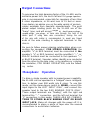
Monophonic Operation
To drive a single speaker with increased power capability,
the XL-600 can be operated in a “bridged” mono configura-
tion, to deliver over 900 watts into 8 ohms. To use this
mode, set the stereo/mono switch to MONO, connect the
input signal to the LEFT INPUT ONLY, and connect the
speaker load to the two RED BINDING POSTS ONLY.
These output terminals are “floating”, with the right red
terminal the
"-”
connection, and the left red terminal the
“+” connection. In this mode, THERE ARE NO CONNEC-
TIONS TO EITHER BLACK BINDING POST OR RIGHT
INPUT JACK. Make all changes with the power off. It is
recommended to place a piece of tape over the unused
connections to avoid later confusion.
4
16 gauge speaker
single
dual banana plugs
spade plugs
pin plugs

Grounding
The XL-600 employs a common ground between the two
channels, which, for the input, is connected directly to
chassis, and for the output, is connected to chassis through
a 5 ohm thermistor to avoid ground loops. This common
ground allows the use of external devices which also have
common grounds, such as headphone or speaker switch-
ing boxes. Make sure that the
“-",
or black terminal of the
amplifier is connected to the corresponding terminal of the
accessory device.
OPERATION
Power Switch and Pilot Lamp
The red bar above the power switch will glow when the
power is switched on unless excessive, long term, heat
sink temperature has opened a thermal breaker, or the AC
line fuse has blown. If the unit has tripped off thermally,
reduce the input signal to avoid high turn-on level. The red
pilot bar will light a few seconds before operation is auto-
matically restored if the XL-600 has cooled down and the
power switch is left on. If a second shutdown occurs,
check for inadequate ventilation, continued excessive
input signal, or a severely reduced load impedance.
Belayed Turn On and Protective Relay
To avoid the turn-on transients generated by some
preamplifiers, the XL-600 provides a 3 second delay before
a relay connects the output terminals, If your preamp
requires a longer delay period, consult the factory on
extending the delay. The relay will also disconnect the
load if significant DC is present at the output, or if the short
term heat sink temperature becomes excessive, while
allowing the fan to continue cooling the amplifier.
5

Initial System Check Out
After initial set-up, leave the XL-600 switched off (rocker
switch to the left) and turn on the rest of the system. Wait
30 seconds, and switch on the amplifier. If you hear a loud
sharp “thump” from the speakers, or no sound is heard
after the relay engages and signal is applied, consult the
section "In Case of Difficulty” at the end of this manual.
Mono / Stereo Switch
This switch should be left in the STEREO position, unless
bridged operation is desired, as outlined in the section
“Monophonic Operation”.
Speaker Fuses
The fuse holders on the back panel provide a measure of
protection against excessive power output to the speakers.
They are not intended to protect the amplifier. The XL-600
is supplied with 5 ampere fast blow fuses installed. This
value will afford minimal protection for most speakers. A
spare pair of 10 ampere fast blow fuses has been included,
for testing purposes, or high power applications. This fuse
value will offer no speaker protection. IF THE MANUFAC-
TURER OF YOUR LOUDSPEAKER RECOMMENDS A
SPECIFIC FUSE VALUE, OBTAIN TYPE 3AG OR AGC
FUSES AND INSTALL THEM IN THE BACK PANEL
FUSE HOLDERS.
THE EXCELINEAR CONCEIT
The purpose of the Excelinear technology is to detect and
then minimize all possible non-linearities, or distortions.
This is done by subtracting the output of the amplifier from
its input, A perfect amplifier would have no residual signal.
The less difference signal that remains, the better the
amplifier. The test described below enables you to hear
only the difference signal- the sum total of all audible
6
3AG
AGC

amplifier distortion, It will already be exceedingly low on
the XL-600 as you receive it because each amplifier chan-
nel has been factory adjusted using a typical loudspeaker
load. But when the XL-600 is connected to your own
speakers, careful readjustment by a technician may yield
some slight improvement. The test is as sensitive as one’s
hearing, and much more precise than available measure-
ment technology because it is able to reveal the audible
effect of all distortions
-
even those which have not yet
been identified or quantified!
This is a very useful amplifier comparative technique which
supplements conventional distortion measurements. With
the XL-600, the total of all residual distortion products will
be on the order of 60
dB
or more down across the audio
band
-
a substantial improvement over other amplifiers,
where 40 dB figures are among the best. Only a few
amplifiers cannot be subjected to this test: those which are
phase inverting, and those which have floating (not
grounded) outputs, or those which cannot tie together the
output grounds.
The XL-600 provides a unique internal adjustment for “fine
tuning” each channel when it is connected to your
speakers. This “tweaking” may fairly be described as
significant only to those persons with “golden ears”. The
rest of us who simply wish to indulge ourselves with fine
sound need not be concerned with this consummate pur-
suit of perfection.
The range of adjustment provided is within the defined
operating specifications of the amplifier. Misadjustment
will not damage or impair the performance of either
amplifier or speaker. The region of change is several
octaves above the range of human hearing. Yet we have
found that minute differences in absolute linearity can be
heard, and this “tweaking” can minimize them. Do not
change the factory’s setting until you have at hand the
appropriate gain control circuit described below. You will
need the special tool provided, patience, quiet, and good
hearing, but no test instruments to complete the task.
Because the amplifier must be operated with the cover off,
and high voltages are exposed, this should only be
undertaken by a qualified technician.
7

A pair of headphones which have a high degree of isolation
from outside sounds may simplify your test listening, but
are not essential. If a very sensitive meter is available, it
can replace the listening requirement, but your ears are
better than conventional meters. Using a loudspeaker,
what you hear is what (distortion) you get.
PERFORMING THE ADJUSTMENTS
One channel of the amplifier may be used as a driving
source to provide a signal at a conventional listening level;
the other is the tested amplifier. These are then inter-
changed to enable adjustment of both channels. Any type
of signal may be used
-
music, white or pink noise, etc.
The accuracy of the driving amplifier is not a factor
-
if it
1 has distortion, that distortion is simply a part of the test
signal, and does not detract from the test accuracy.
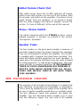
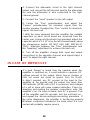
The circuit diagram shows the appropriate connections,
and the values which provide a precise attenuator to adjust
the gain so that the output level will exactly match the input
level. The monitor loudspeaker is connected differentrally
across the outputs of the two amplrfiers.
If the signals are
identical, there will be no sound from the monitor
loudspeaker. Any differences between the input to and
output from the test amplifier represent some form of
distortion, and this will be audible in the monitor speaker,
either as program related content, or as noise.
The monitor speaker is not a part of the load, and it may
be replaced by headphones, or by an AC voltmeter which
can read down to 0.001 volt. It is preferable to use a similar
speaker for monitoring, because you hear the distortion
products at realistic levels and content. It makes compara-
tive evaluation of amplifiers more representative. A good
amplifier will have low distortion, so you will have to Iisten
very carefully, close to the speaker, to achieve the best
null. Since the load speaker’s very audible output would
interfere with listening to the much weaker signal from the
monitor speaker, it must be moved to another room. How-
ever, headphones which have earcups which are effective
seals may enable you to make the adjustment without
having to move the speaker. Because headphones are
8

much more sensitive than speakers, however, the relative
loudness of the residual distortion may be misleading.
The test procedure is as follows:
1.
First use the right channel of the XL-600 as the driving
amplifier and the left channel as the test amplifier. Turn off
the amplifier each time before making any change in
connections, and before removing the cover.
2. Connect a speaker to the right channel speaker ter-
minals to first obtain a normal listening level by adjusting
the preamp’s volume control. A convenient signal is the
interstation noise from an FM tuner with its muting deac-
tivated. This is similar to white, or uniform broad band
noise.
3. Now reconnect
this
“Monitor” speaker (here you may
instead use headphones or a meter) between the left and
right red binding posts.
SCHEMATIC DIAGRAM FOR AMPLIFIER STRAIGHT WIRE DIFFERENTIAL TEST
MONITOR
HEADPHONES
SPEAKER
I LOAD
SPEAKER
T
* wirewound potentiometer not suitable
(all resistor values in Ohms)
9

4. Connect the attenuator circuit to the right channel
output, and connect the left channel input to the attenuator.
Be sure the attenuator is also connected to the right
channel ground.
5. Connect the “Load” speaker to the left output
8. Center the “Fine” potentiometer, and adjust the
“Coarse” potentiometer for minimum signal from the
monitor speaker. Readjust the “Fine” control for minimum
signal -the best null.
7. With the cover removed from the amplifier, the variable
capacitors on each circuit board are accessed from the
center rear. Using only the plastic tool provided, adjust the
capacitor which is 1-1 /4” in on the left channel board, above
the stereo/mono switch. DO NOT USE ANY METALLIC
TOOL. Alternate between the “Fine” potentiometer and
this “tweaking” adjustment to achieve the best null,
8. Turn off the amplifier, change both input and output
connections to the opposite channel, and repeat steps
6
and 7 to adjust the right channel.
IN CASE OF DIFFICULTY
If a loud “thump” is heard from the speaker when the
amplifier is switched on, it could indicate a spurious DC
voltage present at the output. Minor turn-on thumps or
clicks are normal and should be ignored. Since the XL-600
is direct coupled, any DC present at the input to the
amplifier
will
be passed onto the output. Any more than
100 millivolts (1/10th volt) of DC is excessive, and voltages
of a volt or more will cause speaker distortion. Check by
breaking and making the speaker connections
while
the
amplifier
IS on. If a noise is heard, then DC is present. Turn
off the amplifier, wait 30 seconds, turn the unit back on,
and repeat the disconnecting/reconnecting procedure. If
the noise disappears, the amplifier is functioning properly.
~ Whatever component introduces the noise when it is con-
nected will probably require service.
10

If the pilot lamp does not glow when the amplifier is turned
on, and it is not due to an excessive temperature condition,
then either the internal 15 ampere line fuse is blown, or the
circuit breaker or fuse supplying the AC power has inter-
rupted power.
If no sound is heard once the relay engages and an input
signal is applied, check all input and output
connections,
as well as the back panel speaker protection fuses.
In addition to the internal 15 ampere line fuse, there are
four 10 amp rail fuses, None of these internal fuses are
intended to be user replaceable, and a blown condition
usually indicates a need for professional service.
FACTORY SERVICE
&
LIMITED WARRANTY
If you encounter any difficulty or have any questions con-
cerning your XL-600 amplifier, please call our Customer
Service Department weekdays, 8 am to
3:30
pm Moun-
tain Standard time, at 602-967-3565.
Before returning any unit to the factory for service, please
call us. All units being returned (regardless of warranty
status) must receive a Return Authorization (RA) Number.
In addition, we can offer trouble-shooting assistance that
may often simplify or even eliminate the need for factory
service.
The Hafler XL-600 is warranted for 3 years from date of
purchase, including parts, labor, and return shipping costs
from the factory to the owner within the Continental USA.
It is the owner’s responsibility to pay shipping (preferably
UPS) to the factory: collect shipments will not be accepted.
Units under warranty should be accompanied by a copy of
a dated Bill Of Sale. Use the original carton and all packing
material, and be sure to include a return address, and a
brief description of the difficulty, including whether
it
is
intermittent.
This warranty gives you specific legal rights. You may also
have other rights which vary from state to state.
11
-
 1
1
-
 2
2
-
 3
3
-
 4
4
-
 5
5
-
 6
6
-
 7
7
-
 8
8
-
 9
9
-
 10
10
-
 11
11
-
 12
12


Hafler XL-600 Amplifier Owner's manual
- Category
- Home audio sets
- Type
- Owner's manual
- This manual is also suitable for
Ask a question and I''ll find the answer in the document
Finding information in a document is now easier with AI
Related papers
-
Hafler XL-280 Amplifier User manual
-
-
-
-
-
-
-
-
-
Other documents
-
Bryston 2 Way Owner's manual
-
Peavey 400 Owner's manual
-
Box-Design Amp Box S Mono Product information
-
 Sunfire Classic Vacuum Tube Control Center User manual
-
Adcom GTP-600 User manual
-
Fender PX-2200 Series Owner's manual
-
 DYNACO Dynakit ST-70 User manual
-
Shure SR105 User guide
-
Niles SI-1230 Series 2 Installation & Operation Manual
-

