Desa CD32M-B Owner's manual

Category
Fireplaces
Type
Owner's manual
For more information, visit www.desatech.com
WARNING: If the information in this manual is not fol-


         


WHAT TO DO IF YOU SMELL GAS
 
Do not touch any electrical switch; do not use any

 

 

 -

      

DIRECT VENT FIREPLACE
OWNER’S OPERATION AND INSTALLATION MANUAL
MODELS WITH FAN
CD32M-B, CD36M-B, CD42M-A
MODELS WITH FAN & DOOR SWITCH
CD36M-B2, CD42M-A2
www.desatech.com
119212-01B2
    -
       
-

   


-





in accordance with the manufacturers instructions and
the Manufactured Home Construction and Safety Stan-

     



TABLE OF CONTENTS
Introduction .......................................................... 3
Selecting Location ............................................... 3
Pre-Installation Preparation .................................. 4
Installation ........................................................... 7
Burner Flame Adjustment .................................. 19
Operating Fireplace ........................................... 20
Gas Conversion ................................................. 21
Troubleshooting ................................................. 23
Illustrated Parts Breakdown and Parts List........ 24
Specications .................................................... 28
Wiring Diagram .................................................. 28
Accessories and Replacement Parts................. 29
SAVE THIS BOOK




www.desatech.com
119212-01B 3
INTRODUCTION
-




Models CD32M-B, CD36M-B series and
CD42M-A series are heat circulating gravity
direct vent replaces with sealed combustion
chamber. These replaces use millivolt gas
control valve and millivolt ignition system.
These fireplaces are convertible with the
standard setup as natural gas. Conversion
may be performed by the OEM mobile home
builder or by a qualied service person on-
site. If you are uncertain as to what gas your
unit is equipped for, please check the rating
plate located inside of the appliance opening
or consult your mobile home supplier or your
local distributor of DESA/Vexar products.
   
-

BEFORE YOU BEGIN
Before beginning the installation of your
appliance, read these instructions through
completely.
This DESA/Vexar replace and its compo-
nents are safe when installed according to
this installation manual and operated as
recommended. Unless you use DESA/Vexar
components designed and tested for this re-
place system, YOU MAY CAUSE A SAFETY

The DESA/Vexar warranty will be voided by,
and DESA/Vexar disclaims any responsibility
for the following actions:
A) Modication to the replace, components,
doors, blower, fans or vent system.
B) Use of any component part not manu-
factured or approved by DESA/Vexar in
combination with a DESA/Vexar replace
system.
Proper installation is the most important step
in ensuring safe and continuous operation of
the replace. Consult the local building codes
as to the particular requirements concerned
with the installation of all factory built re-
places. This replace, when installed, must be
electrically grounded in accordance with local
codes or in the absence of local codes, with
the National Electrical Code, ANSI/NFPA 70 or
the Canadian Electrical Code, CSA C22.1.
The installation must conform with local codes
or, in the absence of local codes, with the
National Fuel Gas Code, ANSI Z223.1 or the
Canadian Installation Code, CAN/CGA B149.
This appliance complies with ANSI Z21.88-
1998 and CSA 2.33-M98 as a vented gas
replace heater.
SELECTING LOCATION
To determine the safest and most efcient
location for your replace, consider the fol-
lowing guidelines:
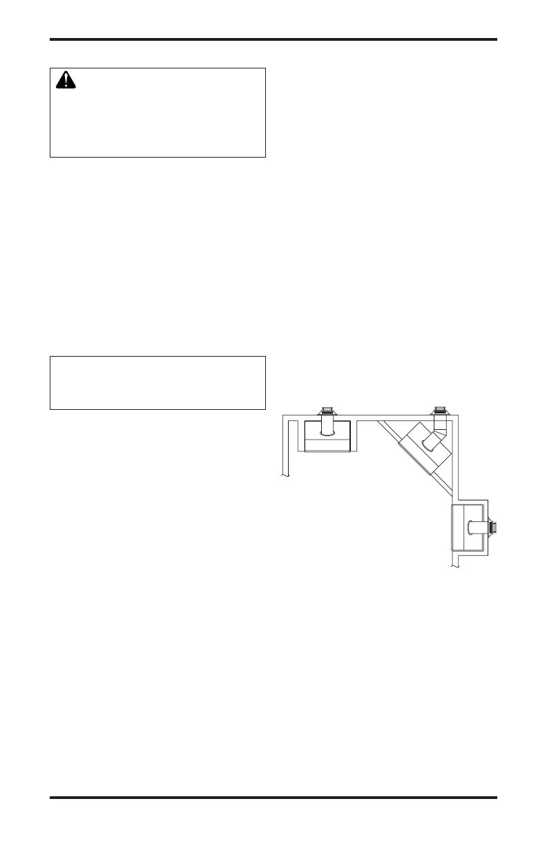
1. The location must allow for proper clear-
ances (see Figure 1).
Flush installation is recommended where
living space is limited.
Projected installation may be ideal for
a new addition to an existing nished
wall.
Corner installation makes use of a space
that may not normally be used and pro-
vides a wider and more efcient range
for radiant heat transfer.
Figure 1 - Common Fireplace Locations
FULL
PROJECTION
CORNER
INSTALLATION
FLUSH
INSTALLATION
2. Consider a location where the replace
would not be affected by drafts, air con-
ditioning ducts, windows or doors.
3. A location that avoids the cutting of joists
or roof rafters makes ventilation installation
easier.
In selecting a location, the following precau-
tions must be observed:
Do not connect this appliance to a chim-
ney system used for solid fuel burning
replace.
Due to high temperatures, do not locate
this appliance in high trafc areas or near
furniture and draperies.
www.desatech.com
119212-01B4
SELECTING LOCATION
Continued
Never obstruct the openings of the appli-
ance or ow of ventilation air. Keep the
control compartments accessible.
Do not locate appliance close to where
gasoline or other ammable liquids may be
stored. The appliance must be kept clear
and free from combustible materials.
Do not use this appliance if any part has
been under water. Immediately contact a
local service technician to examine the
appliance and to replace any part(s) of the
control ignition system and other related
components that have been submerged
under water.
PRE-INSTALLATION
PREPARATION
    
-

   
    

CLEARANCES TO COMBUSTIBLES
Minimum clearances to combustibles for the
replace are:
Back and Sides of Fireplace . . . . . . . . 0"
Floor . . . . . . . . . . . . . . . . . . . . . . . . . . 0"
Perpendicular Wall . . . . . . . . . . . . . . . 6"
Front . . . . . . . . . . . . . . . . . . . . . . . . . 36"
Top of Standoffs . . . . . . . . . . . . . . . . . . 0"
MANTEL CLEARANCES
Woodwork, such as wood trims, mantles
and other combustible materials should be
placed within the required clearance speci-
ed in Figure 2.
Figure 2 - Mantel Clearances
C
B
A
D
E
F
G
Top of Louver Opening
3
2
1
4
5
6
7
Wall
Mantel



(1) 14" (A) 16"
(2) 12" (B) 14"
(3) 10" (C) 12"
(4) 8" (D) 10"
(5) 6" (E) 8"
(6) 4" (F) 6"
(7) 2" (G) 4"
www.desatech.com
119212-01B 5
VENT TERMINATION CLEARANCES
The nal position of your replace depends on
the location of the vent termination in relation
to the clearances that must be observed as
shown in Figure 5 on page 6.
The vent system serves as the “chimney” as
well as the combustion air supply (air intake).
The horizontal run must have a rise of 1/4"
(0.6 cm) for every 12" (30.48 cm) of horizontal
run towards the termination. The maximum
horizontal run depends on the vertical rise
from the replace adapter collar to the vent
termination (see table below).
VERTICAL HORIZONTAL
0 to 1 ft (30.48 cm)
1 ft (30.48 cm) to 4 ft (121.92 cm)
2 ft (60.96 cm) to 8 ft (243.84 cm)
3 ft (91.44 cm) to 12 ft (365.76 cm)
4 ft (121.92 cm) to 16 ft (487.68 cm)
5 ft (152.40 cm) to 15 ft (457.20 cm)
6 ft (182.88 cm) to 14 ft (426.72 cm)
7 ft (213.36 cm) to 13 ft (396.24 cm)
8 ft (243.84 cm) to 12 ft (365.76 cm)
WARNING: Never allow the
vent to run downward as this
-

WARNING: Horizontal sec-

a minimum clearance of 2" from
-
    
Vertical sections of this system
-
   

FRAMING
Once the nal location has been determined,
observing height clearances for vent termina-
tion, you may construct framing using dimen-
sions shown in Figures 3 and 4, depending on
your installation.
PRE-INSTALLATION
PREPARATION
Continued
CD32M-B CD36M-B CD42M-A
A 32
3
/
8
" 36
1
/
8
" 40
1
/
8
"
B 34
5
/
8
" 41
1
/
4
" 48
1
/
4
"
C 19" 23
1
/
2
" 25
5
/
8
"
Figure 3 - Framing Dimension
Figure 4 - Corner Installation
A
B
E
F
G
H
D
C
Nailing Tabs
B
A
C
CD32M-B CD36M-B CD42M-A
A 28
1
/
2
" 35
3
/
4
" 41
5
/
8
"
B 13
5
/
8
" 15" 21
5
/
8
"
C 39
3
/
8
" 49
5
/
8
" 58
1
/
2
"
D 9
1
/
2
" 10
3
/
8
" 13
1
/
2
"
E 9
7
/
8
" 13
3
/
4
" 16
3
/
4
"
F 34
3
/
8
" 41" 48"
G 34
5
/
8
" 41
1
/
4
" 48
1
/
4
"
H 54
1
/
8
" 68
1
/
2
" 81
1
/
2
"
If the appliance is to be installed directly on
carpeting, tile (other than ceramic) or any
combustible material other than wood ooring,
the appliance must be installed on a metal or
wood panel extending the full width and depth
of the appliance.
www.desatech.com
119212-01B6
Fixed
Closed
Openable
Fixed
Closed
V
V
V
V
V
V
V
V
X
X
V
X
G
G
J
F
B
B
K
N
H
I
A
N
E
L
D
B
M
A
C
B
V
V
A
G
G
B
TERMINATION CAP
AIR SUPPLY INLET
GAS METER RESTRICTED AREA
(TERMINATION PROHIBITED)
A = clearance above grade, veranda, porch, deck, or
balcony [*12" (30.5 cm) minimum]
B = clearance to window or door that may be opened
[6" (15 cm) min. for 10,000 Btu or less; 9" (23 cm) in US
if between 10,000 and 50,000, 12" (30 cm) in Canada
if between 10,000 and 100,000; 12" (30 cm) in US if
greater than 50,000, 36" (91 cm) in Canada if greater
than 100,000]
C = clearance to permanently closed window
[minimum 12" (30.5 cm) recommended to prevent
condensation on window]
D = vertical clearance to ventilated soffit located above the
terminal within a horizontal distance of 24" (61 cm) from
the center-line of the terminal [18" (45.7 cm) minimum]
E = clearance to unventilated soffit [12" (30.5 cm) minimum]
F = clearance to outside corner (see below)
G = clearance to inside corner (see below)
H = *not to be installed above a meter/regulator assembly
within 36" (91.4 cm) horizontally from the center line
of the regulator
I = clearance to service regulator vent outlet [*72" (182.9 cm)
minimum]
J = clearance to non-mechanical air supply inlet to building
or the combustion air inlet to any other fireplace
[6" (15 cm) min. for 10,000 Btu or less; 9" (23 cm) in US
if between 10,000 and 50,000, 12" (30 cm) in Canada
if between 10,000 and 100,000; 12" (30 cm) in US if
greater than 50,000, 36" (91 cm) in Canada if greater
than 100,000]
K = clearance to a mechanical air supply inlet [*In Canada,
6 ft. (1.83m) minimum; In US 3 ft. (91 cm) above if within
10 ft. (3 m) horizontally]
L = † clearance above paved side-walk or a paved driveway
located on public property [*84" (213.3 cm) minimum]
M = clearance under veranda, porch, deck
[*12" (30.5 cm) minimum ‡]
N = clearance above a roof shall extend a minimum of
24" (61 cm) above the highest point when it passes
through the roof surface and any other obstruction within
a horizontal distance of 18" (45.7 cm)
vent shall not terminate directly above a side-walk or paved driveway which is located between two
single family dwellings and serves both dwellings*
only permitted if veranda, porch, deck or balconey is fully open on a minimum of 2 sides beneath the floor*
* as specified in CAN/CSA B149 (.1 or .2) Installation Codes (1991) for Canada and U.S.A.
Note: Local codes or regulations may require different clearances
A = 6" (15.2 cm)
Inside Corner
V
B
E
V
B = 6" (15.2 cm)
C = Maximum depth of 48" (121.9 cm)
for recessed location
D = Minimum width for back wall of
recessed location -
Combustible - 38" (965 mm)
Noncombustible - 24" (61 cm)
E = Clearance from corner in
recessed location-
Combustible - 6" (15.2 cm)
Noncombustible - 2" (5.1 cm)
Outside Corner Recessed Location
G
H
G = 12" (30.5 cm) minimum clearance
Balcony with No Side Wall
V
J
Combustible &
Noncombustible
H = 24" (61 cm)
J = 20" (50.8 cm)
Balcony with Perpendicular Side Wall
C
D
C
Termination Clearances for Buildings with Combustible and Noncombustible Exteriors
Openable
Figure 5 - Minimum Clearances for Vent Terminations
PRE-INSTALLATION PREPARATION
Continued
www.desatech.com
119212-01B 7
INSTALLATION
WARNING: Read all instruc-

  
Failure to do so could result in
   -

-
   


NOTICE: Failure to follow these in-

VENTING INSTALLATION

Consult local building codes before beginning
the installation. The installer must make sure
to select the proper vent system for instal-
lation. Before installing vent kit, the installer
must read this replace manual and vent kit
instructions.
Only a qualied service person should install
venting system. The installer must follow
these safety rules:
Wear gloves and safety glasses for protec-
tion
Use extreme caution when using ladders
or when on roof tops
Be aware of electrical wiring locations in
walls and ceilings
The following actions will void the warranty
on your venting system:
Installation of any damaged venting compo-
nent
Unauthorized modification of the venting
system
Installation of any component part not
manufactured or approved by DESA
Installation other than as instructed by
these instructions
-



    



-



WARNING: Horizontal sec-

a minimum clearance of 2" from
-
    
Vertical sections of this system
-
   

VENTING INSTALLATION
1. Install elbow to replace collar adapter
located on back of the unit at a 45° angle.
Slide elbow over collar and twist to lock.
Check to insure proper connection (see
Figure 6).
2. Continue to install remainder of pipe for
desired installation. Make sure each sec-
tion is twist-locked securely.
3. When installation of vent pipe is complete,
in stall vent termination. Depending on the
location of your replace, you will vent
vertically or horizontally.
Figure 6 - Venting Installation
Female
Locking Lugs
Male
Locking Lugs
Vertical Flue
Restrictor
(For Vertical
Venting
Application)
www.desatech.com
119212-01B8
Figure 7 - Vent Termination (Horizontal)
Direct vent
Pipe
Wall Firestop
Maintain 1"
Minimum
Air Space
Around Outer
Pipe when
Penetrating a
Wall
Horizontal
Termination
(Vent Cap)
Screws
Exterior Wall
with Vinyl
Siding
Deector
Shield
Minimum Pipe
Overlap 1
1
/
4
"
Siding Standoff
(Optional)
10
3
/
4
" x 10
3
/
4
"
Framed Opening
4. Allow 1" of pipe to protrude from internal
wall, depending on wall thickness. See
Figure 7, page 8.
5. For horizontal installation, an optional
siding standoff may be installed between
the vent cap and the exterior wall. Secure
horizontal vent cap to standoff. Secure
standoff/vent cap assembly to wall (see
Figure 7). Do not seal termination to vent
pipe. The vent termination must be remov-
able for service pipe inspection.
6. For vertical installation, a vertical termi-
nation is available. A vertical ue restrictor
must be installed into inner collar of re-
place as shown in Figure 6, page 7.
When installing a length of pipe for vertical
termination that is over 3 ft., support the
pipe every 3 ft. using metal wall straps.
Vertical to horizontal pipe must be kept at
a 1 ft. to 4 ft. ratio with a maximum run of
no more than 20 ft.
If an offset is necessary in the attic to
avoid obstruction, it is important to sup-
port the vent pipe every 3 ft. to avoid
excessive stress on the elbows and
possible separation (see Figure 8).
INSTALLATION
Continued
Figure 8 - Vertical Termination with
Offset and Wall Strap
Wall
Strap
Roof
Flashing
45° Elbows
Ceiling Firestop

Figures 9 through 13 show different congura-
tions and alternatives for venting with horizontal
termination. Each gure includes a chart with
critical minimum and maximum dimensions
which MUST be met. IMPORTANT: Remem-
ber that a horizontal run of venting must have
a 1/4" rise for every 12" of run toward the
termination.
WARNING: Never run vent
downward as this may cause
  

-
   


GROUND FLOOR INSTALLATION
Recommended Applications:
Installation using cabinet surrounds
Through the wall using round or square
termination (up to 12” horizontal pipe)
NOT FOR CORNER INSTALLATION

Recommended Applications:
Corner ground oor installation
Ground oor installation where pipe vents
horizontally through wall (over 12" horizon-
tal pipe)
Basement installation where one foot
clearance from ground to termination is
possible
www.desatech.com
119212-01B 9
  
29
3
/
4
" min. 17" max. CD32
32
3
/
4
" min. 17" max. CD36
36
3
/
4
" min. 17" max. CD42
Horizontal High
Wind Square
Termination
Wall
Firestop
45° Elbow
Adjustable Pipe
12" Max.

INSTALLATION
Continued
Figure 9 - Horizontal Termination
Conguration for Square and Round
Terminations
45° Elbow
Wall
Firestop
Round
Termination
Cap
Exterior Portion of
Wall Firestop (Round
Termination Only)
Round Termination
Slide Ring
Over Elbow
to Complete
Connection
CD32 Series
Vertical (V)
Minimum
CD36 Series
Vertical (V)
Minimum
CD42 Series
Vertical (V)
Minimum
Required
Vertical Pipe
Horizontal (H)
Maximum
*40
1
/
2
" *43
1
/
2
" *46
1
/
4
" None 30"
51
1
/
2
" 54
1
/
2
" 57
1
/
4
" 1 ft. 48"
63
1
/
2
" 66
1
/
2
" 69
1
/
4
" 2 ft. 60"
75
1
/
2
" 78
1
/
2
" 81
1
/
4
" 3 ft. 84"
87
1
/
2
" 90
1
/
2
" 93
1
/
4
" 4 ft. 20'
Figure 10 - Horizontal Termination
Conguration for Corner Installation
Using One 90° Elbow
Square
Termination
Wall
Firestop
Not to Exceed
(H) Limits
As Required
for (V)
See Chart
for Pipe
Section
Required
45°
Elbow
90° Elbow
90° Elbow
Square
Termination
Wall
Firestop
45° Elbow
12"
Minimum
*Note: Ground Floor Corner Venting
Not to Exceed
(H) Limits
www.desatech.com
119212-01B10
INSTALLATION
Continued
Vertical (V) Horizontal (H
1
)
Horizontal (H
1
) +
Horizontal (H
2
)
5' min. 2' max. 6' max.
6' min. 4' max. 12' max.
7' min. 6' max. 18' max.
8' min. 8' max. 20' max.
20' max. 8' max. 20' max.
45° Elbow

The following congurations show the minimum vertical rise requirements for a horizontal
system using two 90° elbows.

Figure 12 - Horizontal Termination Conguration for Venting Using Two 90° Elbows
with Termination at 90° with Fireplace
45° Elbow

Figure 11 - Horizontal Termination Conguration for Venting Using Two 90° Elbows
Vertical (V) Horizontal (H
1
) +
Horizontal (H
2
)
5' min. 6' max.
6' min. 12' max.
7' min. 18' max.
8' min. 20' max.
20' max. 20' max.
www.desatech.com
119212-01B 11
INSTALLATION FOR VERTICAL
TERMINATION
Note

1. Determine the route your vertical venting
will take. If ceiling joists, roof rafters, or
other framing will obstruct the venting
system, consider an offset (see Figure 19)
to avoid cutting load bearing members.
Note: Pay special attention to these instal-
lation instructions for required clearances
(air space) to combustibles when passing
through ceilings, walls, roofs, enclosures,
attic rafters, etc. Do not pack air spaces
with insulation. Also note maximum verti-
cal rise of the venting system and any
maximum horizontal offset limitations.
2. Set the replace in desired location. Drop
a plumb line down from the ceiling to the
position of the replace exit ue. Mark the
center point where the vent will penetrate
the ceiling. Drill a small locating hole at
this point.
Drop a plumb line from the inside of the
roof to the locating hole in the ceiling.
Mark the center point where the vent will
penetrate the roof. Drill a small locating
hole at this point.
Figure 13 - Offset with Wall Strap and 45°
Elbows
45° Elbow
Wall Strap
Roof
Flashing
Ceiling Firestop
INSTALLATION
Continued

Figures 14 through 17 show four different
congurations for vertical termination.
Vertical (V)
Horizontal (H
1
) +
Horizontal (H
2
)
5' min. 2' max.
6' min. 4' max.
7' min. 6' max.
8' min. 8' max.
20' max. 8' max.
Figure 14 - Vertical Venting
Conguration Using Two 90° Elbows
with Two Horizontal Runs (Vertical
Round High Wind Termination Shown)
Note: Install
restrictor into
inner collar of
replace as
shown.
45° Elbow

www.desatech.com
119212-01B12

REMOTE RECEIVER DIAGRAM
An outlet box with two receptacles (see Figure
18) has been supplied for your convenience
and is located inside on the lower right side of
the replace.
Figure 18 - Duplex Outlet
Three-prong Plug
Outlet Box
INSTALLATION
Continued
Vertical (V) Horizontal (H)
5' min. 2' max.
6' min. 4' max.
7' min. 6' max.
8' min. 8' max.
20' max. 8' max.
Figure 15 - Vertical Venting Conguration
Using One 90° Elbow (Vertical Round
High Wind Termination Shown)
Note: Install restrictor
into inner collar of
replace as shown.
Vertical
(V
1
)
Horizontal
(H)
5' min. 6' max.
6' min. 12' max.
7' min. 18' max.
8' min. 20' max.
Note: Vertical (V
1
) +
Vertical (V
2
) = 40’ max.
Figure 16 - Vertical Venting Conguration
Using Two 90° Elbows (Vertical Round
High Wind Termination Shown)
Note: Install restrictor
into inner collar of
replace as shown.
45° Elbow
45° Elbow




V = 40’ max.
Figure 17 - Vertical Venting Conguration
With No Horizontal Run (Vertical Round
High Wind Termination Shown)
Note: Install restrictor
into inner collar of
replace as shown.
45° Elbow
www.desatech.com
119212-01B 13
INSTALLATION
Continued
Figure 19 - Remote Control Receiver
Remote
Control
Receiver
Convertible
Gas Valve

NOTICE: This section is in-



WARNING: Do not connect
-

valve may result and an unsafe

The appliance and its individual shutoff valve
must be disconnected from the gas supply
piping system during any pressure testing of
that system at test pressures in excess of 1/2
psig (3.5 kPa).
The appliance must be isolated from the gas
supply piping system by closing its individual
shutoff valve during any pressure testing of
the gas supply piping system at test pressures
equal to or less than 1/2 psig (3.5 kPa).
The gas control valve is secured underneath
the rebox. Two 1/8" ports are provided on
the gas control valve for pressure test gauge
connections (see Figure 20).
Figure 20 - Gas Control Valve
ON/OFF
Knob
Pilot Adjustment
Inlet
Pressure
Outlet
Pressure
Flame
Adjustment Knob
Pilot Gas Line
Do Not Kink
To Pilot
Burner
To Main
Burner

   

    

-


An equipment shutoff valve has been included
in the replace's gas supply system. Consider
installing an extra shutoff valve outside the ap-
pliance’s enclosure (check local codes), where
it can be accessed more conveniently with a
key through a wall as shown in Figure 21.
In conformance with local codes, route a 1/2"
NPT gas line towards the appliance coming in
from either the bottom, left or right side of the
replace (see Figure 22, page 14).
Figure 21- Typical Exterior Wall Gas
Shutoff Installation
Key
Extension
Shutoff
Valve
The remote control receiver is factory wired
and connected to the convertible gas valve
as shown in Figure 19.
www.desatech.com
119212-01B14
Install a sediment trap between incoming gas
line and gas control box (see Figure 23). The
sediment trap should extend down a minimum
of 3" (7.62 cm) beyond center of pipe.
When routing gas line through conduit sleeve,
make sure to repack insulation to ll gaps
between gas line and conduit sleeve. Com-
pounds used on threaded joints of gas piping
shall be resistant to the action of propane or
natural gas. Compounds should be applied
lightly to ensure excess sealant does not
enter gas line.
Complete your gas line installation by con-
necting incoming gas line to flexible gas
line. Secure tightly with a wrench but do not
over-tighten.
    



     

      -
   
     




INSTALLATION
Continued
Figure 22 - Gas Line Routing
Gas Routing
(Right Side Not Shown)
Side of
Fireplace
Front Face
Figure 23 - Sediment Trap
Sediment Trap
(Not Supplied)
Incoming 1/2" Gas Line
Permitted By Local Codes
3" Min.
(7.6 cm)

The pilot or electrode assembly is factory
preset for proper ame height. Alterations
to these settings may have occurred during
shipping and handling. If this is the case, some
minor readjustments may be necessary and
should be done by a qualied service techni-
cian. The proper settings for the thermopile
height should be at a distance of 3/8" (0.95
cm) to 1/2" (1.27 cm) from the pilot ame as
shown in Figure 24.
Figure 24 - Pilot Assembly
1/8"
(0.3 cm)
3/8" - 1/2"
(.95cm-1.3 cm)

  -


1. To remove louvers, pull both spring
latches (located in each end of louver)
toward center of appliance at the same
time until disengaged from locating holes.
Repeat for bottom end spring latches (see
Figure 25, page 15).
2. Remove screen rod by removing rod loop
from glass door center bracket. Slide
screen rod either to the left or right of re-
place until one end is free to completely
remove screen from replace.
www.desatech.com
119212-01B 15
Figure 25 - Removing Louvers
Figure 26 - Spring Latches
Glass
Locating
Holes
Spring
Latch
Bottom Louver
Open
Close
INSTALLATION
Continued
3. Undo latches located on top and bottom
of rebox (see Figure 26). Carefully swing
door to the left. The glass door is securely
mounted to the rebox with 5 screws.

HAND-HELD REMOTE CONTROL

-

Some fireplaces have the remote control
already installed. If a remote control is not
installed in your replace see Accessories
and Replacement Parts, page 29.

1. Open bottom louver and locate the switch
bracket on the right.
2. Unscrew switch bracket. Lean bracket
forward so you are able to access back
of remote receiver.
3. Locate battery clip mounted on back of
receiver. Slide a 9-volt alkaline battery (not
included) through clip (see Figure 27).
4. Attach terminal wires to battery.
Figure 27 - Attaching Alkaline Battery to
Receiver
Figure 28 - Control Valve Terminals
To Optional
Remote
Accessory
9-Volt
Alkaline
Battery
Receiver
Terminal
Wires
Battery Clip
To Wall
Thermostat
5. Connect wires from receiver to TH and
TPTH on control valve (see Figure 28).
6. Replace the switch bracket.
Figure 29 - Installing Battery in Hand-
Held Remote Control Unit
9-Volt
Battery
Battery
Housing
Battery Cover
Terminal
Wires
Remote Control Unit

Held Remote Control Unit
1. Remove battery cover on back of remote
control unit.
2. Attach terminal wires to a 9-volt alkaline
battery (not included). Place battery into
battery housing.
3. Replace battery cover onto remote control
unit.
www.desatech.com
119212-01B16
INSTALLING LOG SET
Each log is marked with a number in the fol-
lowing illustrations. These numbers will help to
identify logs when installed. It is very important
to install these logs exactly as instructed. Do
not modify logs. Only use logs supplied with
replace.

1. Place log #1 (back log) on top of grate
as shown in Figure 30 for the CD36M-B
Series. Log #1 will go in front of the metal
partition on grate (see Figure 30). Make
sure notches in bottom of log t over
grate.
2. Place log #2 (large front log) over pins on
grate (see Figure 31).
Figure 30 - Installing Log #1
(CD36M-B Series Shown)
Figure 31 - Installing Log #2
(CD36M-B Series Shown)
1
2
CD32M
Log #1
Placement
3
Figure 32 - Installing Log #3
(CD36M-B Series Shown)
Figure 33 - Installing Log #4
(CD36M-B Series Shown)
5
6
Figure 34 - Installing Logs #5 and #6
(CD36M-B Series Shown)
INSTALLATION
Continued
3. Place log #3 (c-shaped crossover log)
onto rear and front logs as shown in Fig-
ure 32. Make sure it is seated properly on
the smooth surface on front log and on the
pin on back log.
4. Place log #4 (small round log) on pin on
right side of front log (see Figure 33).
5. Place log #5 (small front log) onto the front
left part of grate making sure notches t
over prongs of grate (see Figure 34).
www.desatech.com
119212-01B 17
6. Place log #6 onto two pins on left side
of back and front logs (see Figure 34,
page 16).
Model CD42M-A Series
1. Place log #1 (small base log) onto pin
on left side of grate extension (see
Figure 35).
2. Rest left side of log #2 (front log) on top
of log #1 and right side onto pin located
on right side of grate extension (see
Figure 36).
3. Place log #3 (rear log) onto pins on rear
of grate (see Figure 37).
4. Place log #4 (crossover log) onto pins from
both logs #2 and #3 (see Figure 38).
5. Place log #5 (top log) onto right pin of front
log (#2) and smooth surface of rear log
(#3). Make sure it is seated properly (see
Figure 39).
6. Place log #6 (left log) on left pin of front
log (#2) and smooth surface of rear log
(#3). Make sure it is seated properly (see
Figure 40).
7. Place log #7 (right log) on right pin of top
log (#5). Make sure it is seated properly
(see Figure 40).
INSTALLATION
Continued
Figure 35 - Installing Log #1, Model
CD42M-A
Figure 36 - Installing Log #2, Model
CD42M-A
Figure 37 - Installing Log #3, Model
CD42M-A
1
1
2
3
Figure 38 - Installing Log #4, Model
CD42M-A
Figure 39 - Installing Log #5, Model
CD42M-A
Figure 40 - Installing Logs #6 and #7,
Model CD42M-A
5
6
7
4
www.desatech.com
119212-01B18

1. For all models, place lava rock along sides
and front of rebox bottom in areas that
are visible. It is not necessary to use all
lava rock provided.
     
    


2. Pull ember material apart into pieces no
larger than a dime. Place loosely and di-
rectly onto exposed section of front burner
and along space between burner and grate
prongs. These will create glowing ember ap-
pearance as ame touches ember material.
Do not block air slots by using too much
ember material in one area. It is not neces-
sary to use all ember material provided.
3. When lava rock and ember material are
in place, close and latch glass door and
secure louvers in place.
   

-


DECORATIVE FACING
Any noncombustible material may be used as
facing (glass, tile, brick, etc.) as long as the
proper clearances are observed (see Clear-
ances to Combustibles, page 4). Louvered
openings must not be obstructed and upper
and lower panels must remain accessible for
service. Use only heat-resistant, noncom-
bustible mortar or adhesive when securing
decorative facing materials.
INSTALLATION
Continued
FACE EXTENSION FOR MODEL

Model CD32M-B comes equipped with a
front face extension. The front face extension
would add 3
1
/
2
" to the width and 3/4" to the
height of the replace face.
To install face extension:
1. Remove existing screws from front face
assembly as shown in Figure 41.
2. Align holes on top face extension with
holes on top side of front face assembly
and secure with screws previously re-
moved (see Figure 41).
3. Align holes on right face extension with
holes on right side of front face assembly
and secure with screws previously re-
moved (see Figure 41). Do the same for
left side.
4. Secure top face extension with left and
right face extensions with two sheet metal
screws (see Figure 41).
Figure 41 - Front Face Extension, Model
CD32M-B Only
Side Face
Extensions
Top Face
Extension
www.desatech.com
119212-01B 19
BURNER FLAME
ADJUSTMENT
The burner ame adjustment (shutter open-
ing) has been factory preset (for natural gas)
to the proper air-to-gas ratio. This ratio results
in an even, clean burning ame across the
burner (see Figure 42).
If adjustment is necessary, you can restore
the proper ame setting by loosening the air
shutter screw and rotating the air shutter until
proper setting is achieved (see Figure 43).
The correct shutter openings are as follows:
Figure 42 - Burner Flame Patterns
CORRECT
INCORRECT
CLOSE
SHUTTER
INCORRECT
OPEN
SHUTTER
Short, Sharp, Blowing Flame
Long, Blue Flame with Yellow Tips
Long, Uneven, Yellow Flame
Tube Burner Pan Burner
Model NG LP NG LP
CD32M-B 0.188" Max.
CD36M-B 0.188" Max
CD42M-A 0.188" 0.313" 0.188" 0.500"
-
-
vice or maintenance can cause

    


Figure 43 - Air Shutter Adjustments
Manifold
Air Shutter
Opening
Firebox
Bottom
Burner
Gas Line
Burner Pan
Burner
Tube
Adjustment Screw
Adjustment
Screw
Manifold
Air Shutter
Opening
Burner
Gas Line
Firebox
Bottom
www.desatech.com
119212-01B20
 
    
 



LIGHTING
INSTRUCTIONS
 -

 
      

 
 
 
 




 
 -
wise 
 
-
     -





       -
-

       
      
and call your service technician or

    -
wise 



 

Note: It is recommended that you maintain
       -
     

OPERATING FIREPLACE

When used for the rst time, the replace
may emit a slight odor for about 16 to 24
hours. This is normal and is due to the “cur-
ing” of the logs and the “burn-in” of internal
paint and lubricant used in the manufactur-
ing process.
Keep compartments, logs, burners and
area surrounding logs clean by vacuuming
and brushing at least twice a year or as
necessary.
Turn off gas and remote switch before
servicing appliance. Any safety screen or
guard removed for servicing the replace
must be replaced prior to operation.
Have a qualied agency periodically inspect
vent system at the start of each heating
season for any obstruction which will hin-
der its normal operation. Never obstruct
the ow of combustion and ventilation air.
Keep the front of the replace clear of all
obstacles and materials.
FOR YOUR SAFETY
READ BEFORE LIGHTING
WARNING: If you do not fol-
low these instructions exactly,
     
-

 
-

     




WHAT TO DO IF YOU SMELL GAS

Do not touch any electric switch; do

    




 

       



  • Page 1 1
  • Page 2 2
  • Page 3 3
  • Page 4 4
  • Page 5 5
  • Page 6 6
  • Page 7 7
  • Page 8 8
  • Page 9 9
  • Page 10 10
  • Page 11 11
  • Page 12 12
  • Page 13 13
  • Page 14 14
  • Page 15 15
  • Page 16 16
  • Page 17 17
  • Page 18 18
  • Page 19 19
  • Page 20 20
  • Page 21 21
  • Page 22 22
  • Page 23 23
  • Page 24 24
  • Page 25 25
  • Page 26 26
  • Page 27 27
  • Page 28 28
  • Page 29 29
  • Page 30 30
  • Page 31 31
  • Page 32 32

Desa CD32M-B Owner's manual

Category
Fireplaces
Type
Owner's manual

Ask a question and I''ll find the answer in the document

Finding information in a document is now easier with AI