
Owner's Manual
®
Liquid Propane Gas Grill
Model 141.152270
Z_ WARNING:
Read this Owner's Manual carefully and be sure
your gas grill is properly assembled, installed and
maintained. Failure to follow these instructions
could result in serious bodily injury and/or property
damage. This gas grill is intended for outdoor use
only and is not intended to be installed in or on
recreational vehicles or boats.
Note to Installer: Leave this Owner's Manual
with the consumer after delivery and/or installation.
Note to Consumer: Leave this Owner's Manual
in a convenient place for future reference.
Sears, Roebuck and Co.,
Hoffman Estates, IL 60179 U.S.A.
P47B7E - Rev: 05/02/2002

Warranty ..................................................... 2
Safety Instructions ..................................... 2
Pre-Assembly Instructions ......................... 4
Hardware, Parts Diagram and Lists ..... 5
Assembly Instructions ................................. 9
Lighting Instructions .................................. 16
Cleaning and Maintenance Instructions .... 18
Frequently Asked Questions .................. 20
Cooking Instructions ................................ 21
Cooking Guide and Recipes ................ 22
Full 1-Year Warranty on Grill
For one year from the date of purchase Sears will
repair or replace, at our option, any grill part
(except for paint loss, rusting and ignitor battery)
that is defective in material or workmanship.
Limited Warranty on Selected Grill Parts
From one year after the date of purchase for the
designated time periods listed below, Sears will
replace the following grill parts if they are defective
in material or workmanship. You will be charged
for labor.
• Lifetime of Grill: Aluminum Castings (except for paint
loss)
• 1 Year: Cast Iron Burners
• 2 Years: All Other Grill Parts (except flame tamers,
cooking grids and ignitor battery)
Warranty Service
Warranty service is available by contacting the
nearest Sears Service Center at 1-800-4-MY-HOME
®
Warranty Restrictions
• This warranty is void if grill is used for commer-
cial or rental purposes.
• This grill is for use with Liquid Propane (LP)
gas only. Any attempt to convert this grill to
natural gas is dangerous and will void your
product warranty.
• This warranty applies only when the grill is
used in the United States.
• This warranty gives you specific legal rights,
and you may also have other rights which vary
from state to state.
Sears, Roebuck and Co., Dept. 817WA,
Hoffman Estates, IL 60179
Z_ WARNI NG
Combustion byproducts produced when using
this product contain chemicals known to the
State of California to cause cancer, birth
defects, or other reproductive harm.
Z_ WARNI NG
Failure to comply with these instructions
could result in a fire or explosion that
could cause serious bodily injury, death, or
property damage.
Z_ WARNI NG
Your grill will get very hot. Never lean over
the cooking area while using your grill. Do not
touch cooking surfaces, grill housing, Lid or any
other grill parts while the grill is in operation, or
until the grill has cooled down after use.
Failure to comply with these instructions
may result in serious bodily injury.
FOR YOUR SAFETY
1. Do not store or use gasoline or other flam-
mable material and liquids in the vicinity of this
or any other appliance.
2. An LP cylinder not connected for use shall not
be stored in the vicinity of this or any other
appliance.
FOR YOUR SAFETY
If you smell gas:
1. Shut off gas to the appliance.
2. Extinguish any open flame.
3. Open Lid.
4. If odor continues, immediately call your gas
supplier or your fire department.
Grill Installation Codes
This gas grill must be installed in accordance with
all local codes. In areas without local codes, follow
the latest edition of the National Fuel Gas Code
ANSI Z223.1. and National Electrical Code ANSI/
NFPA 70 In Canada, installation must conform to
standard CAN/CGA lb149.1 or 1-b149.2 (Installation
Code for Gas Burning Appliances and Equipment)
and all local codes.
Correct LP Gas Tank Use
LP gas grill models are designed for use with a
standard 20 lb. Liquid Propane Gas (LP gas) tank,
not included with grill box. Never connect your gas
grill to an LP gas tank that exceeds this capacity.
A tank of approximately 12 inches in diameter by
2 © Sears, Roebuck and Co.

18-1/2incheshighis themaximumsizeLPgas
tankto use.You must usean "OPD"gas tank
whichoffersan OverfillPreventionDevice.
Thissafetyfeaturepreventsthetankfrombeing
overfilledwhichcancausemalfunctionoftheLP
gastank,regulatorand/orgrill.
TheLPgastankmustbeconstructedand
markedinaccordancewithspecificationsof theU.
S.Dept.ofTransportation(DOT).InCanada,the
LPgastankmustmeettheCanadianTransporta-
tionandCommunications(CTC)specifications.Also
besureto readandfollowall LPinstructions
below.
1. TheLPgastankhasa shutoffvalve,termi-
natinginan LPgas supplytankvalveoutlet,
that iscompatiblewith a Type1 tankcon-
nectiondevice.TheLPgastankmustalso
havea safetyreliefdevicethathasa direct
communicationwiththevaporspaceof the
tank.
2. Thetanksupplysystemmustbearranged
forvaporwithdrawal.
3. TheLPgastankusedmusthavea collar
to protectthetankvalve.
Proper Placement and Clearance of Grill
Never use your gas grill in a garage, porch, shed,
breezeway or any other enclosed area. Your gas grill is
to be used outdoors only, at least 24 inches from the
back and side of any combustible surface. Your
gas grill should not be placed under any surface
that will burn. Do not obstruct the flow of ventilation
air around the gas grill housing.
This outdoor gas grill is not intended to be installed in
or on recreational vehicles and/or boats.
• Never connect an unregulated LP gas tank to
your gas grill. The gas regulator assembly
supplied with your gas grill is adjusted to have
an outlet pressure of 11" water column (W.C.)
for connection to an LP gas tank.
• Only use the regulator and hose assembly
supplied with your gas grill. Replacement
regulators and hose assemblies must be those
specified by Sears.
• Have your LP gas tank filled by a reputable
propane gas dealer and visually inspected and
re-qualified at each filling.
• Never fill the gas tank beyond 80% full.
Have your propane gas dealer check the
release valve after every filling to ensure that it
remains free of defects.
• Always keep LP gas tanks in an upright
position.
• Do not store (or use) gasoline or other flammable
vapors and liquids in the vicinity of this gas grill.
• An LP gas tank that is not connected for use must
NOT be stored on bottom shelf or in the vicinity of
this or any other gas grill.
• Do not subject the LP gas tank to excessive heat.
• Never store an LP gas tank indoors. If you
store your gas grill in the garage or other indoor
location, always disconnect the LP gas tank
first and store it safely outside.
• LP gas tanks must be stored outdoors in a
well-ventilated area and out of the reach of
children. Disconnected LP gas tanks must not
be stored in a building, garage or any other
enclosed area.
• When your gas grill is not in use the gas
must be turned off at the LP gas tank.
• The regulator and hose assembly must be
inspected before each use of the grill. If there
is excessive abrasion or wear or if the hose
is cut, it must be replaced prior to the grill
being used again.
• Keep the gas regulator hose away from hot
grill surfaces and dripping grease. Avoid
unnecessary twisting of hose. Visually inspect
hose prior to each use for cuts, cracks,
excessive wear or other damage. If the hose
appears damaged do not use the gas grill.
Call Sears at 1-800-366-PART (1-800-366-7278)
for a Sears authorized replacement hose.
• Never light your gas grill with the lid closed
or before checking to insure the burner tubes
are fully seated over the gas valve orifices.
• Never allow children to operate your grill. Do
not allow children to play near your grill.
WARNI NG
A strong gas smell, or the hissing sound of
gas indicates a serious problem with your
gas grill or the LP gas tank. Failure to
immediately follow the steps listed below
could result in a fire or explosion that could
cause serious bodily injury, death, or prop-
erty damage.
• Shut off gas supply to the gas grill.
• Turn the Control Knobs to OFF position.
• Put out any flame with a fire extinguisher.
• Open Grill Lid.
• Get away from the LP gas tank.
• Do not try to fix the problem yourself.
• If odor continues or you have a fire you
cannot extinguish, call your fire department.
Do not call near the LP gas tank because
your telephone is an electrical device and
could create a spark resulting in fire and/or
explosion.
NOTE: The normal flow of gas through the
regulator and hose assembly can create a
humming noise. A low volume of noise is
perfectly normal and will not interfere with
operation of the grill. If humming noise is
loud and excessive you may need to purge
air from the gas line or reset the regulator
excess gas flow device. This purging proce-
dure should be done every time a new LP
gas tank is connected to your grill. For help
with this procedure refer to page 17, step 4,
or call the Customer Service Helpline for
assistance, 8am - 8pm CST, Monday through
Friday 1-888-317-7642.

• Longnoseplierscanbe usedto remove
CotterPinwhencleaningtheBurners
• Useworkglovesto protectyourhands
• Weareyeprotection
• WhenyouhavefinishedassemblingyourGrill
besureall PatternHeadThumbScrews
are tightened.Youmayusethesupplied
TighteningTool(P55M3A)asneeded.
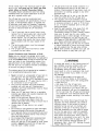
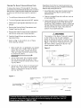
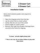
To reducethechanceof "FLASH-BACK"(see
CAUTIONat right)cleantheBurnerTubesand
Burnersbeforefullyassemblingyourgrill.
RemovetheCotterPinfromtherearunderside
of eachBurnerusinga pairof longnosepliers.
Carefullylift eachBurnerupandawayfromthe
GasValveOrifice,thenreferto Figure1 and
performoneofthesethreecleaningmethods:
1. Benda stiffwire,(alightweightcoathanger
workswell)intoa smallhookasshown
below.RunthehookthroughtheBurnerTube
andinsidetheBurnerseveraltimesto remove
anydebris.
t[
2. Use a bottle brush with a flexible handle.
Run the brush through the Burner Tube and
inside the Burner several times, removing any
debris.
3. Use an air hose to force air through each
Burner Tube. The forced air should pass
debris or obstructions through the Burner and
out the Ports.
CAUTION: Spiders and small insects occa-
sionally spin webs or make nests in the grill
Burner Tubes during transit and warehousing.
These webs can lead to a gas flow obstruc-
tion which could result in a fire in and around
the Burner Tubes. This type of fire is known
as a "FLASH-BACK" and can cause serious
damage to your grill and create an unsafe
operating condition for the user.
Although an obstructed burner tube is not the
only cause of "FLASH-BACK', it is the most
common cause.
To reduce the chance of "FLASH-BACK", you
must clean the burner tubes before assem-
bling your grill, and at least once a month in
late summer or early fall when spiders are
most active. Also perform this Burner Tube
cleaning procedure if your grill has not been
used for an extended period of time.
z WARNING
The location of the Burner Tube with re-
spect to the Orifice is vital for safe
operation. Check to ensure the Orifice is
inside of the Burner Tube before using your
gas grill. See Fig. 2. If the Burner Tube
does not fit over the Valve Orifice, lighting
the Burner may cause explosion and/or fire.
Figure 2
GAS VALVE ASSEMBLY
ORIFICE BURNER TUBE
Figure 1
GAS COLLECTOR BOX
SPARK ELECTRODE AS- / BURNER BURNER PORT
TO CLEAN BURNER TUBE, ,................. , _ ................ o o o o o o o o o o _
INSERT HOOK__HERE _ -- '_
L_jL _Z" FOOT
BURNER TUBE COTTER PIN

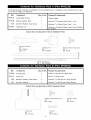
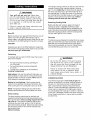
The following table illustrates a breakdown of the hardware pack. It highlights what components are used
in the various stages of assembly.
Ref.
H019
H017
H017
H019
H017
H021
H022
H017
H018
H023
P8080A
P0271A
P5589A
Component Qty. to Use
1/4"x2" Pattern Head Screw 8
1/4"xl/2" Pattern Head Screw 4
1/4"xl/2" Pattern Head Screw 4
1/4"x2" Pattern Head Screw 4
1/4"xl/2" Pattern Head Screw 4
1/4"xl/2" Part-Threaded Bolt 4
M4x5mm Pattern Head Screw 4
1/4"xl/2" Pattern Head Screw 4
1/4"x3/4" Pattern Head Screw 8
1/4"x4" Wind Bolt 1
AA Battery 1
Door Handle 2
Magnetic Door Stop 2
Purpose of Components
Attaches Cart Legs To Bottom Shelf
Attaches Tank Pull-Out Tray Kit To Bottom Shelf
Attaches Rear Panel To Cart
Attaches Door Bracket To Cart
Attaches Door Stops To Cart
Attaches Doors To Cart
Attaches Door Handles To Doors
Attaches Grill Head To Cart
Attaches Side Shelf and Side Burner To The
Grill Head
Secure Gas Tank
Powers The Electric Ignitor
Attaches To Front Doors
Attaches To Cart
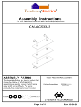
Actual Size and Quantity of Each Hardware Piece:
1/4"x4" Wind Bolt
Qty. 1
Ref. # H023
1/4"x2" Pattern Head Screw
Qty. 12
Ref. # H019
1/4"x3/4" Pattern Head Screw M4x5mm Pattern Head Screw
Qty. 8 Qty. 4
Ref. # H018 Ref. # H022
1/4"xl/2" Pattern Head Screw
Qty. 16
Ref. # H017
1/4"xl/2" Part-Threaded Bolt AA Battery
Qty. 4 Qty. 1
Ref. # H021 Ref. # P8080A
Scale 1:2
Door Handle
Qty. 2
Scale 1:2
Ref. # P0271A Magnetic Door Stop
Qty. 2
Scale 1:2
Ref. # P5589A

The following table illustrates a breakdown of the hardware pack. It highlights what components are used
in the various stages of assembly.
Ref.
P55F5A
P5540B
H025
P55M3A
Component Qty. to Use
Customized Wrench 1
Manual Lighting Stick 1
M4x8mm Pattern Head Screw 1
Tightening Tool 1
Actual Size and Quantity of
Customized Wrench
Qty. 1
Ref. # P55F5A
Scale 1:0.6
Purpose of Components
Tighten Caster
Attaches To Outside Bowl Panel - Left
Attaches To Outside Bowl Panel - Left
Allows you to tighten Pattern Head Thumb Screws
as needed
Each Hardware Piece:
X_
Tightening Tool M4x8mm Pattern Head Screw
Qty. 1 Qty. 1
Ref. # P55M3A Ref. # H025
Manual Lighting Stick
Qty. 1 Ref. # P5540B
Ref.
P3430A
P55L7A
H025
H027
Component Qty. to Use
Control Knob 1
Cotter Pin 1
M4x8mm Pattern Head Screw 2
M4 Plain Washer 2
Purpose of Components
Install To Side Burner Valve Stem
Secure To Side burner
Attaches To Side Burner Valve Bracket
Attaches To Side Burner Valve Bracket
Actual Size and Quantity of Each Hardware Piece:
s
I
_. M4x8mm Pattern Head Screw
Qty. 2
Ref. # H025
Control Knob Cotter Pin
Qty. 1 Qty. 1
Ref. # P3430A Ref. # P55L7A
©
M4 Plain Washer
Qty. 2
Ref. # H027

4 1
10\
57 56
19 18 16 23 37 34
67
48
4O
43
52
53
51
35
47
5O
21
26
60 58
61

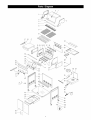
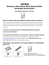
REF# DESCRIPTION PART# QTY
1. Stainless Steel Lid P01AIA 1
2. Lid Side Panel - Left P0164A 1
3. Lid Side Panel - Right P0163A 1
4. Temperature Gauge P0615D 1
5. Lid Handle P0251A 1
6. Heat-Insulating Spacer P5573A 2
7. Name Plate P0468A 1
8. Secondary Cooking Rack -Porcelain P1521E 1
9. Cooking Grid - Porcelain P1661A 2
10. Flame Tamer- Porcelain P1749A 2
11. Main Burner P1935F 4
12. Main Burner Bracket P2230A 1
13. Gas Collector Box w/ Electrode P2618A 2
14. Ignition Wire Set P2637B 1
15. Electric Ignitor P2503G 1
16. Smoker Drawer Bracket PSOF3A 1
17. Smoker Drawer P80F4A 1
18. Bowl Panel - Left P0799A 1
19. Outside Bowl Panel- Left P0755C 1
20. Bowl Panel- Right P07AIA 1
21. Outside Bowl Panel - Right P0758C 1
22. Bowl Panel - Front P0759B 1
23. Bowl Panel - Rear P0760C 1
24. Wind Shield P80F2A 1
25. Grease Draining Tray P2755A 1
26. Grease Receptacle P2741A 1
27. Gas Manifold P5038A 1
28. Gas Valve for Main Burner P32CIB 4
29. Heat Shield for Control Panel P2999A 1
30. Protective Pad - Heat Resistant P80L5A 2
31. Control Panel P2966A 1
32. Decorative Front Cover P2965A 1
33. Control Knob P3430A 5
34. Back Burner Assembly P1948A 1
35. Gas Valve for Back Burner P32CIC 1
36. Fitting for Back Burner Valve P39A2A 1
37. Electrode for Back Burner P2648A 1
38. Orifice P39A7A 1
39. Extension Tube for Back Burner P39A8A 1
40. Control Knob for Back Burner P3430D 1
41. Side Shelf P1147A 1
42. Side Burner Frame P1174A 1
43. Bottom Shelf P1074A 1
44. Cart Leg -Left P0856A 1
45. Cart Leg -Righ P0857A 1
REF# DESCRIPTION PART# QTY
46. Rear Panel P4356A 1
47. Door Bracket P4413A 1
48. Door Panel P4357A 2
49. Door Handle P0271A 2
50. Magnetic Door Stop P5589A 2
51. Tank Pull-Out Tray P4043A 1
52. Bracket for Tank Pull-Out Tray P4043B 1
53. Slide P55J8A 2
54. Caster P5111B 4
54a Customized Wrench P55F5A 1
55. Caster Seat P4528A 4
56. Tool Holder P80F5A 1
57. Tool Hook P80FTC 5
58. Side Burner Lid P0199A 1
59. Pot Support P80F7A 1
60. Side Burner Electrode P2627A 1
61. Side Burner P1959A 1
62. Gas Valve for Side Burner P32DIB 1
63. Extension Tube for Side Burner P3983G 1
84. Regulator and Hose P3632P 1
65. Reinforcing-Bracket for Grill Bowl P80PIA 1
66. Manual Lighting Stick P5540B 1
67. Heat Shield for Grease Tray P80P6A 1
68. Tightening Tool P55M3A 1
--- Owner's Manual P47B7E 1
--- Hardware Pack P55K5A 1
--- Hardware Pack A P55L3B 1
--- Hardware Pack B P55K5C 1
For the repair or replacement parts you need:
Call 6 am - 11 pm CST, 7 days a week
1-8 00-366-PART (1-800-366-7278)
To make sure you obtain the correct replacement
parts for your Kenmore gas grill, please refer to
the part numbers on this page. The following
information is required to assure you receive the
correct parts:
1. Grill Model Number (see CSA label on grill)
2. Part Number
3. Part Description
4. Quantity of parts needed
Important: Keep this Owner's Manual for convenient
referral and for part replacement.
Important: Use only Sears authorized parts. The
use of any part that is not Sears authorized can
be dangerous and wilt also void your product
warranty.

CAUTION:Whileitispossibleforonepersonto
Figure 1
CART LEG
assemble this grill, obtain assistance from another person
when handling some of the larger, heavier pieces, espe-
cially the grill head.
1. Open Lid of shipping carton and remove top sheet of
cardboard. Lay cardboard sheet on floor and use as a
work surface to protect floor and grill parts from
scratches.
2. Remove packing materials and cart parts from
shipping carton.
3. You may slice the carton front corners with a utility
knife to lay open the carton front panel. This wilt
allow you to raise the grill head Lid and remove the
components packed inside the head, making it
easier to lift.
4. With an assistant, lift the grill head out of the ship-
ping carton and place it on the cardboard work sur-
face.
5. Use the parts list to check that all parts have been
included.
6. Inspect the grill for damage as you assemble it. Do
not assemble or operate the grill if it appears
damaged. If there are damaged or missing parts
when you unpack the shipping box, or you have
questions during the assembly process, call:
1-888-317-7642
8 a.m. - 8 p.m CST, Mon.- Fri.
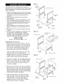
Assembling The Grill Cart
1. Before attaching the Bottom Shelf to the Cart
Legs be sure the holes for the Door Stop on
Bottom Shelf are located on the front side. Be
sure the Cart Leg Brackets and air vents all
face outward. Cart Leg Bracket-Right has a
semi-circle cutout at top front. See Fig. 1.
Install the Bottom Shelf between the Cart Legs.
Align the holes on Cart Legs with the
threaded holes at the corners of Bottom Shelf.
Tighten securely by using 8 of the 1/4"x2"
Pattern Head Screws provided. See Fig. 1.
BOTTOM
SHELF
HOLES FOR
DOORSTOP
Figure 2
CART LEG -LEFT
BOTTOM
SHELF
Figure 3
-RIGHT
SEAT
CASTER
TANK PULL-OUT
TRAY KIT T
CART LEG - RIGHT
2. Screw the 4 Casters into the Caster Seats (see
bottom of Cart Legs). Turn the threaded Caster
Stem by hand, clockwise until it stops. Tighten
securely by using the Customized Wrench
provided. See Fig. 1.
CART LEG -LEFT
REAR PANEL
3. Place the Tank Pull-Out Tray Kit on the Bottom
Shelf. Extend the Tank Tray outward from the
Bracket so you can align the holes on the Bracket
with the threaded holes on the top of Bottom Shelf.
Tighten securely by using 4 of the 1/4"xl/2" Pattern
Head Screws provided. See Fig. 2.
4. Install the Rear Panel to inside of rear Cart
Legs making sure that air vents face outward.
Align the holes on the Rear Panel with the
threaded holes on rear Cart Legs. Tighten
securely by using 4 of the 1/4"x1/2" Pattern
Head Screws provided. See Fig. 3.
DO0
BRACKET
BOTTOM
SHELF
CART LEG - RIGHT

Install the Door Bracket to the inside of front
Cart Legs. Align the threaded holes on the Door
Bracket with the holes on Cart Legs. Tighten
securely by using 4 of the 1/4"x2" Pattern Head
Screws provided. (See Fig. 3. on page 9) Upper
door bolt holes (at ends of bracket) must face
outward.
Installing The Cabinet Doors
1. Install the Door Stops to the Bottom Shelf
and the Door Bracket. See Fig. 4.
Align the holes on the Door Stops with the
threaded holes on the top of the Bottom Shelf
and bottom side of Door Bracket. Tighten
securely by using 4 of the 1/4"x1/2" Pattern
Head Screws provided. See Fig.4.
2. Remove the white protective film from the
stainless steel Doors. Attach a Door Handle to
each Front Door by using 2 of the M4x5mm
Pattern Head Screws provided. See Fig. 5. Be
careful not to scratch the Door surfaces.
3. When installing the Front Doors, make sure
the door bolt holes are located on the hinge
sides of the Cart Legs.
4. Install either Front Door by inserting 1/4"xl/2"
part-threaded bolt through the lower door bolt
hole of the Front Door and into the tapped
hole of the Bottom Shelf. Next, align the
upper door bolt hole of Front Door with the
tapped hole in the bottom of Door Bracket.
Insert 1/4"x1/2" part-threaded bolt provided and
tighten both securely.
5. Repeat these steps to install the other Front Door.
Figure 4
DOOR
BRACKET
DOOR
Found in
Hardware Pack
BOTTOMSHELF
Figure 5
DOOR
BRACKET
UPPER DOOR
BOLT HOLE
FRONT
DOOR
DOOR
HANDLE
\
LOWER DOOR
BOLT HOLE
TANK PULL-OUT
TRAY KIT
BOTTOM
SHELF
Installing The Grill Head
Now that you've assembled the grill cart you
can install the pre-assembled Grill Head. See
Fig. 6. If you haven't already done so, we
suggest you open the Grill Lid and remove
the packed components. Even with the com-
ponents removed, this next step requires 2
people.
With an assistant, lift and position the Grill
Head onto the grill cart. Align the 4 holes of
the Bowl Side Panel to the threaded holes
on the Cart Leg Bracket. Secure firmly by
using 4 of the 1/4"x1/2" Pattern Head Screws
provided.
Figure 6
GRILL
HEAD
CARTLEG
BRACKET
CART ;:;>
PRE-ASSEMBLED
VALVE KIT
2. Place the Pre-assembled Valve Kit and Ignition
Wire through the slot in side of Grill Head as
illustrated in Fig. 6.
IGNITION WIRE
FROM GRILL HEAD
.
Place Heat Shield into Grease Draining Tray.
The Heat Shield must be present and
centered for your safety. From the back
10
CART LEG - RIGHT

side of Grill Head, install the Grease Draining
Traywith its drain hole to left, which is the
side opposite from the Tank Pull-Out Tray.
See Fig. 7.
From the front side of cabinet, open the front
doors and Install the Grease Receptacle under
Grease Draining Tray. See Fig. 7.
Figure 7
GRILL
HEAD
\
GREASE
DRAIN-
ING
TRAY
HEAT
SHIELD
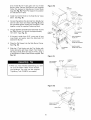
Installing Manual Lighting Stick
Attach the Manual Lighting Stick to the Left
Bowl Support Bracket as shown in Fig. 8.
Align the hole at the end of Manual Lighting
Stick Wire with the threaded hole on the Left
Bowl Support Bracket. Tighten securely using
the M4x8mm Pattern Head Screw packed with
the Manual Liqhtinq Stick.
Figure 8
FRONT
DOOR
GREASE
RECEPTACLE
;EMBLED
VALVE KIT
Figure 9
SIDE SHELF FRAME
GRILL HEAD
PANEL-LEFT
M4x8mm PATTERN
HEAD SCREW
MANUAL LIGHTING
STICK
SIDE BURNER
FRAME
Installing Side Shelf, Side Burner and Tool
Holder Kit
Remove Side Burner from Side Burner Kit before
installing.
Enlisting the aid of an assistant, attach Side Burner
Frame to right side of grill. Attach Side Shelf
Frame to left side of grill as shown in Fig. 9.
Align the 4 holes on Side Shelf Frame and Side
Burner Frame with the threaded holes on left and
right Bowl Support Brackets. Tighten securely
using 4 of the 1/4"x3/4" Pattern Head Screws
provided.
Install the Pre-assembled Valve Kit to the Side
Burner Frame. See Fig. 9a. Attach the Pre-
assembled Valve Kit to the Side Burner Valve Hole
on the Side Burner Frame, as shown in Fig. 9a.
Align the 2 holes on the Side Burner Frame with
the threaded holes on the Side Burner Valve
Bracket. Tighten securely using 2 of M4x8mm
Pattern Head Screws and 2 Washers packed with
the Control Knob.
Cut Fastening Band from Pot Support and set
Pot support aside. Install the Side Burner through
the top hole in Side Burner Frame and onto the
Side Burner Valve. Make sure that opening at
BOWL SUPPORT
BRACKET-RIGHT
Figure 9a
M4x8mm _"_'_
PATTERN HEAD
SCREW AND
WASHER
11
HOLES FOR SIDE
BURNER VALVE KIT
BURNER
FRAME
EMBLED
VALVE KIT
BURNER
VALVE BRACKET

.
.
.
7.
.
.
end of Side Burner Tube goes over tip of Side
Burner Valve. Secure Side Burner with supplied
Cotter Pin (packed in Side Burner Control Knob
bag) See Fig. 9b. Place Pot Support into position
on Side Burner Frame.
Install the Control Knob to the Side Burner Valve
Stem. See Fig. 9b.
Connect the Ignition Wire terminal from Side Burner
with the other from Grill Head. See Fig. 9b. Bind
the connected Ignition Wires and Connection Tube
together using the supplied Fastening Band.
The gap between the Side Burner Electrode Tip and
the Side Burner Port should be approximately
1/8"~3/16 ''. See Fig. 9c.
If the gap is wider than 3/16", use a pair of long
nose pliers and gently bend the Electrode Tip
toward the Burner.
Place the Pot Support into the Side Burner Frame.
See Fig. 9b.
Slide the 5 Tool Hooks onto the Tool Holder with
hooks facing the grill Head. Attach Toot Holder to
left side of Side Shelf and secure firmly using 2
of the M5x8mm Pattern Head Screws supplied. See
Fig. 9d.
• When you have finished assembling your Grill
be sure aN Pattern Head Thumb Screws
are tightened. You may use the supplied
Tightening Tool (P55M3A) as needed.
Figure 9b
POT
SUPPORT
\
SIDE
JRNER
COTTER
PIN
BAND
PRE-ASSEMBLED
VALVE KIT
IGNITION WIRE
FROM SIDE BURNER
3NITION WIRE
FROM GRILL HEAD
Figure 9c
1/8"~3/16" BURNER
SIDE BURNER _ PORT
_URNER
Figure 9d
TOOL HOLDER
TOOLHOOK
M5x8mm PATTERN
HEAD SCREW
SIDE SHELF
12

Ignitor Battery Installation - See Fig. 10
1. Unscrew the Ignitor Cap located on the grill
Control Panel and remove the Contact and
Spring from the Ignitor Slot.
2. Place the manufacturer supplied AA battery
into the Ignitor Slot. Be sure to place the
positive pole facing toward you. See Fig. 10.
Place the Spring over the AA battery, then
place the Contact on top of the Spring.
Screw the Ignitor Cap back onto the grill
Control Panel.
Remove all protective film from outside and
inside of Grill Head. IMPORTANT: Before
use of this grill please refer to Cleaning
Exterior Stainless Steel Surfaces found on
page 18 of this Owner's Manual.
Figure 10
IGNITOR SLOT
IGNITOR CAP
\
CONTACT
AABATTERY
SPRING
13
Electrode Check - Requires an Assistant
Before placing the cooking components into your
grill, ensure that the Spark Electrode Tip is properly
positioned within each Gas Collector Box (a
3-1/4" wide stainless mechanism found at the front
between each set of Burners.) The easiest way to
ensure this is to perform this Electrode Check:
1. Be sure alt Control Knobs are set to "OFF"
and open the Grill Lid.
2. Have an assistant stand behind to the right of
the grill and look down at each Gas Collector
Box. NEVER put your face inside Grill Head.
Press the Ignitor Cap. You should hear a
"clicking" sound and your assistant should see
a small blue spark within each Gas Collector
Box. If a spark is present the Electrode Tips
are properly positioned.
4. If no spark is seen the Spark Gap shown in
Fig. 11 needs to be adjusted as follows:
Using an adjustable wrench, loosen the Inside Nut
just until the Gas Collector Box can be maneuvered
and turned upward.
The gap between the Spark Electrode Tip and
Spark receiver should be approximately 3/16".
If the gap is wider than 3/16" use a pair of long nose
pliers and gently squeeze the Gas Collector Box
until the gap is correct.
Return the Gas Collector Box to its original horizon-
tal position, secure the Inside Nut and try the
Electrode Check again.
If no "clicking" sound is heard check the
following common causes. If you need assis-
tance call our Customer Service Helpline
at 1-888-317-7642.
• IgnitorAAbattery not installed properly.
• Ignitor wires may be loose. Remove the AA battery,
inspect the Ignitor Junction Box found behind the
Control Panel, and connect any loose wires.
Figure 11 - Side View
GAS COLLECTOR BOX
SPARK RECEIVER

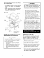
Installing Cooking Components
Figure 12
Important: Before cooking on your grill the first
time, wash the Cooking Grids and Cooking Rack
with warm, soapy water. Rinse and dry thoroughly.
Season with cooking oil regularly. After cooking is
completed, turn grill to HIGH setting three to five
minutes to burn off excess grease or food residue.
1. Place the two Flame Tamers on the lower
ledge above Burners. See Fig. 12.
2. Evenly space the Cooking Grids (cross braces
are bottom side) on the ledge above the
Flame Tamers.
3. Place the Secondary Cooking Rack into the
slots on the upper left and upper right of Grill
Bowl Side Panels. See Fig. 12.
.
Install the Smoker Drawer into the opening on
the upper left side of Control Panel. Slide the
Smoker Drawer on the Smoker Drawer Bracket
inside grill.
Connecting A Liquid Propane Gas (LPgas)
Tank To Your Grill
1. Open the front Doors of cabinet. Pull out the
LPG Tank Pull-Out Tray. Place the 20 Ib tank
with foot ring into the hole in the tray. See
Fig.13a. Make sure the tank valve is in the
OFF positon.
SECONDARY
COOKING RACK
COOKING GRID
FLAME TAMER
SLOTSFOR
RACK
SMOKER
DRAWER
BURNER
.
.
4.
5.
.
Align the tank so the Tank Valve faces the
rear right corner of cabinet. See Fig. 13a. Use
the 1/4"x4" Wing Bolt to secure gas tank.
Check the tank valve to insure it has proper
external mating threads to fit the hose &
regulator assembly provided (Type 1 connection
per ANSI Z21.58a-1998). See Fig.13b (on page
15)
Make sure all Burner Valves are in the OFF
position.
Inspect the valve connection port and regulator
assembly. Look for damage or debris. Remove
any debris. Inspect hose for damage. Never
use damaged or plugged equipment.
Place the hose and regulator assembly through
gap between the Right Cart Leg and
the Grill Head. When connecting the hose and
regulator assembly to the tank valve (See Fig.
13b) hand tighten Quick Coupling Nut clockwise
to a full stop. DO NOT use a wrench to
tighten because it could damage the Quick
Coupling Nut and result in a hazardous
condition.
Open the tank valve fully (counterclockwise).
Use a soapy water solution to check all
connections for leaks before attempting to light
your grill. See "Checking for LP Gas Leaks"
on page 15. If a leak is found, turn the tank
valve off and do not use your grill until the
leak is repaired.
Figure 13a
FRONT
DOOR
1/4"x4" WING
BOLT
14
TANK PULL-OUT
TRAY

Disconnecting A Liquid Propane Gas (LP gas)
Tank From Your Grill
Turn the Burner Valves and LP gas tank valve
to the full OFF position. (Turn clockwise to
close.)
Detach the hose and regulator assembly from
the LP gas tank valve by turning the Quick
Coupling Nut counterclockwise.
Figure 13b
GRILL HEAD
FRONT
DOOR
\
GAS TAN K
TANK PI
TRAY
QUICK
COUPLING
NUT
ALREADY CONNECTED
TO ADAPTOR UNDER
SIDE BURNER.
CAUTION: When the appliance is not in use, the
gas must be turned off at the supply tank.
Congratulations
Your Kenmore LP gas grill is now ready for
use. Before the first use and at the beginning
of each season (and whenever the LP gas
tank has been changed):
1. Read all safety, lighting and operating
instructions.
2. Check Gas Valve Orifices, Burner Tubes
and Burner Ports for any obstructions.
3. Perform gas leak check according to
instructions found on page 15 of this
manual.
WARNI NG
A strong gas smell, or the hissing sound of
gas indicates a serious problem with your gas
grill or the LP gas tank. Failure to immedi-
ately follow the steps below could result in a
fire or explosion that could cause serious
bodily injury, death, or property damage.
• Shut off gas supply to the gas grill.
• Turn the Control Knobs to OFF position.
• Put out any flame with a fire extinguisher.
• Open Grill Lid.
• Get away from the LP gas tank.
• Do not try to fix the problem yourself.
• If odor continues or you have a fire you
cannot extinguish, call your fire department. Do
not call near the LP gas tank. Your
telephone is an electrical device and could
create a spark resulting in fire and/or explosion.
NOTE: The normal flow of gas through the
regulator and hose assembly can create a
humming noise. A low volume of noise is
normal and will not interfere with operation of
the grill. If humming noise is loud and exces-
sive you may need to purge air from the gas
line or reset the regulator excess gas flow
device. This purging procedure should be done
every time a new LP gas tank is connected
to your grill. For help with this procedure refer
to page 17, step 4, or call for assistance.
Checking For LP Gas Leaks
Never test for leaks with a flame. Prior to first
use, at the beginning of each season, or every
time your LP gas tank is changed, you must
check for gas leaks. Follow these four steps:
1. Make a soap solution by mixing one part liquid
detergent and one part water.
2. Turn the grill Control Knobs to the full OFF
position, then turn the gas ON at source.
3. Apply the soap solution to all gas connections.
If bubbles appear in the solution the connec-
tions are not properly sealed. Check each
fitting and tighten or repair as necessary.
.
If you have a gas leak you cannot repair, turn
off gas at the source, disconnect fuel line from
your grill and call 1-800-4-MY-HOME or y_ur
gas supplier for repair assistance.
15

Basic Lighting Procedures
Machine oils used in the manufacturing process of
stainless steel can cause stainless steel to turn a tan
color. Before initial grill use, removing protective PVC film
from Control Panel and inside and outside of Grill Lid. Use
a Stainless Steel Cleaner to polish the stainless steel and
remove these excess oils from your grill. Never use
abrasive cleaners or scrubbers because they will scratch
and damage your grill. For details, see Cleaning Exterior
Stainless Steel Surfaces on page 18.
1. Familiarize yourself with the safety guidelines at
the front of this manual. Do not smoke while
lighting grill or checking gas supply connections.
2. Be sure the LP gas tank is filled.
3. Check that the end of each Burner Tube is properly
located over each Valve Orifice.
4. Be sure all gas connections are securely tightened.
5. Open the Grill Lid or Side Burner Lid, depending
on the Burner you are lighting.
/!X,WARNING
Failure to open Grill Lid during the
lighting procedures could result in a fire
or explosion that could cause serious
bodily injury, death, or property damage.
.
Set ALL Control Knobs to OFF and open the LP
gas tank valve slowly until 1/4 to 1/2 open.
OFF
Open LP
gas tank
.
10.
11.
If the burner does not light, turn the Control Knob
to OFF, wait 5 minutes for gas to clear, then retry.
Once the left grill burner is ignited, the adjacent
burner can be lit by simply turning its Control
Knob to HIGH.
Adjust Control Knobs to your desired cooking
temperature.
Back Burner Lighting Instructions
Note: The location of the Back Burner makes it more
susceptible to winds that will decrease the perfor-
mance of your rotisserie cooking. For this reason you
should not operate the Back Burner during windy
weather conditions.
1. Follow steps 1,2 and 4 of the Lighting Procedures.
2. Open the Grill Lid. Failure to do so can result in
fire or explosion. See WARNING left.
.
4.
Set ALL Control Knobs to OFF and open the LP
gas tank valve slowly until 1/4 to 1/2 open.
Push and turn the Right Control Knob for Back
Burner to HIGH.
5. Then immediately press the Electric Ignitor for
3-4 seconds to light the Back Burner.
.
7.
If the Burner does not light, turn the Control Knob
to OFF, wait 5 minutes for gas to clear, then retry.
Once lit, the Back Burner will reach cooking
temperature quickly. The orange/red glow will even
out in about 5 minutes.
.
For best results, always rotisserie cook with the
grill Lid down and the Back Burner Control Knob
set to HIGH. Do not use the main grill Burners
when the Back Burner is in operation.
J
7. Push and turn the LEFT Control Knob to HIGH.
OFF
HIGH _
Immediately press the Electric Ignitor for 3-4
seconds to light the Burner.
16

Manually Lighting Your Grill by Match
To light your gas grill by match, insert a match into the
Manual Lighting Stick and follow steps 1 through 6 of
the Basic Lighting Procedures. Then, light the match
and place Manual Lighting Stick through the Lighting
Hole on the left side of the grill. See Fig. 14. Turn the
nearest Control Knob to the HIGH setting to release
gas. The Burner should light immediately.
Figure 14
Misalignment of Ignitor on Burner
Correction: Check for proper position of the
Electrode Tip as shown in Figures 9c and 11.
The gap between the Spark Electrode Tip and
Burner or Spark Receiver should be approxi-
mately 3/16", adjust if necessary. With the gas
supply closed and all Control Knobs set to OFF
press the Electric Ignitor Cap and check for the
presence of a spark at the Electrode.
Disconnected Ignition Wires
Correction: Inspect the Ignitor Junction Box
found behind the Control Panel. Connect loose
Ignitor wires to Junction Box and try to light the
grill.
LIGHTING
HOLE
MANUAL
LIGHTING
STICK
MATCH
WARNING
Never lean over the grill cooking area while
lighting your gas grill. Keep your face and
body a safe distance (at least 18 inches)
from the Lighting Hole or Burners, when
lighting your grill by match.
If the grill fails to light :
1. Turn gas off at source and turn the Control Knob to
OFF. Wait at least five minutes for gas to clear,
then retry.
2. If your grill still fails to light, check gas supply
and connections.
3. Repeat lighting procedure. If your grill still fails
to operate, turn the gas off at source, turn the
Control Knobs to OFF, then check the following:
• Misalignment of Burner Tubes over Orifices
Correction: Reposition Burner Tubes over
Orifices.
• Obstruction in gas line
Correction: Remove fuel line from grill. Do not
smoke[ Open gas supply for one second to clear
any obstruction from fuel line. Close offgas supply
at source and reconnect fuel line to grill.
Plugged Orifice
Correction: Remove Burners from grill by pulling
Cotter Pin (beneath Burner) using Long nose
pliers. Carefully lift each Burner up and away
from gas valve Orifice. Remove the Orifice from
gas valve and gently clear any obstruction with a
fine wire. Then reinstall all Orifices, Burners,
Cotter Pins and cooking components.
If an obstruction is suspected in gas valves or
gas valve bracket, please call for repair service at
1-800-4-MY-HOME. ®
• Obstruction in Burner Tubes
Correction: Follow the Burner Tube cleaning
procedure on page 19 of this Owner's Manual.
• WeakAA battery
Correction: Unscrew the Ignitor Cap and replace
the battery.
If the grill still does not light you may need
to purge air from the gas line or reset the
regulator excess gas flow device. Note: This
procedure should be done every time a new
LP gas tank is connected to your grill.
To purge air from your gas line and/or
reset the regulator excess gas flow device:
• Turn the Control Knobs to the OFF posi-
tion.
• Turn off the gas at the tank valve.
• Disconnect regulator from LP gas tank.
• Let unit stand for 5 minutes.
• Reconnect regulator to the LP gas tank.
• Turn the tank valve on slowly until 1/4 to
1/2 open.
• Open the Grill Lid.
• Set Control Knobs to OFF
Push and turn the LEFT Control Knob to
HIGH.
5. If all checks or corrections have been made and
you still have questions about operating your gas
grill, call the Customer Service Helpline
8am - 8pm CST, Monday through Friday at
1-888-317-7642.
WARNING
Should a "FLASH-BACK" fire occur in/or
around the Burner Tubes, follow the
instructions below. Failure to comply with
these instructions could result in a fire or
explosion that could cause serious bodily
injury, death, or property damage.
• Shut off gas supply to the gas grill.
• Turn the Control Knobs to OFF position.
• Put out any flame with a proper fire
extinguisher.
• Open Grill Lid.
• Once the grill has cooled down, clean the
Burner Tubes and Burners according to
the cleaning instructions found on page 19
in this manual.
17

Aswithallappliances,propercareandmaintenance
wiltkeepyourgrillintopoperatingconditionand
prolongitslife.Byfollowingthesecleaningprocedures
onatimelybasis,yourgrillwillstaycleanandwork
properlywithminimumeffort.
CAUTION:
BesureyourgrillisOFFandcoolbeforecleaning.
Takecarenottochiporscratchthepaintedsurfaces
becauseitwillvoidyourwarrantyagainstrusting.
CleaningTheCookingGrids
Beforeinitialuseandperiodicallywesuggestyouwash
yourCookingGridsinamildsoapandwarmwater
solution.Youcanuseawashclothorvegetablebrush
tocleanyourCookingGrids.
CAUTION:
Takecarenottochiporscratchtheporcelainfinish
becauseitwiltvoidyourwarrantyagainstrusting.
Never try to clean your Cooking Grids unless you
are sure the grids are cool to the touch.
Cleaning The Flame Tamers
Periodically you should wash the Flame Tamers in a
soap and warm water solution. Use a vegetable brush
to remove stubborn burnt-on cooking residue. Dry the
Flame Tamers thoroughly before you reinstall them into
the cooking bowl.
Cleaning The Grease Tray and Receptacle
To reduce the chance of fire, the Grease Draining Tray
and Grease Receptacle should be visually inspected
before each grill use. Remove any grease and wash
Grease Tray and Receptacle with a mild soap and
warm water solution.
Annual Cleaning of The Grill Interior
Burning-off the grill after every cookout wilt keep it
ready for instant use. However, once a year you should
give the entire grill a thorough cleaning to keep it in top
operating condition. Follow these steps:
1. Turn all Burner Valves to the full OFF position.
2. Turn the LP gas tank valve to the full OFF position.
.
Detach the LP gas hose and regulator assembly from
your gas grill. Use a 7/8" open end wrench turning the
fitting counter-clockwise. Inspect for any damage
and replace as necessary with manufactures re-
placement part number found on the Parts List.
4. Remove and clean the Flame Tamers, Cooking
Grids, Cooking Rack and Grill Burners.
18
5. Cover each Gas Valve Orifice with aluminum foil.
.
7.
Brush the inside and bottom of the grill with a fiber
pad or nylon brush, and wash with a mild soap and
warm water solution. Rinse thoroughly and let dry.
Remove aluminum foil from Orifices and check
each Orifice for obstruction.
.
10.
11.
Check each Spark Electrode, adjusting as needed.
The space between the Spark Electrode Tip and
Spark Receiver should be approximately 3/16".
Replace the Burners and adjust the Gas Collector
Box. The edge of the collector box should be
overlapping the Burner Port.
Replace Flame Tamers and the Cooking Grids.
Reconnect the gas source and observe the Burner
flame for correct operation.
Cleaning Exterior Surfaces:
Before initial use, and periodically thereafter, we
suggest you wash your grill using a mild soap and
warm water solution. You can use a wash cloth or
sponge for this process. Do not use a stiff wire or
brass brush that might remove paint during the clean-
ing process.
Cleaning Exterior Stainless Steel Surfaces:
Weathering and extreme heat can cause exterior
stainless steel surfaces to turn tan in color. Machine
oils used in the manufacturing process of stainless
steel can also cause this tanning color. After removing
the protective PVC film from the Grill Lid and Control
Panel use a Stainless Steel Cleaner to polish the
stainless steel surfaces of your grill. Never use abra-
sive cleaners or scrubbers because they will scratch
and damage your grill. Follow these steps for the best
results.
Turn the LP gas tank valve (clockwise) to the full OFF
position. Disconnect the regulator and hose assem-
bly from LP gas tank. Cover exposed gas fitting with
aluminum foil.
2. Remove dirt or grease using a soft cloth and polish
stainless surfaces. Wipe with a soft cloth.
3. Remove aluminum foil from exposed gas fitting and
allow grill to air dry before attaching the regulator
and hose to your LP gas tank.
Keep outdoor cooking gas appliance area clear and free
from combustible materials, gasoline and other flam-
mable vapors and liquids.

Cleaning The Burner Tubes and Burner Ports
To reduce the chance of "FLASH-BACK" the proce-
dure below should be followed at least once a month in
late summer or early fall when spiders are most active
or when your grill has not been used for a period of
time.
1. Turn all Burner Valves to the full OFF position.
2. Turn the LP gas tank valve to the full OFF position.
3. Detach the LP gas regulator assembly from your
gas grill.
4. Remove the Cooking Grids, Flame tamers, and
Grease Trays from your grill.
5. Remove the Cotter Pin from the rear underside of
each Burner using a pair of long nose pliers.
6. Carefully lift each Burner up and away from the
Gas Valve Orifice.
7. Refer to Fig. 1 and perform one of these
three cleaning methods:
Bend a stiff wire, (a lightweight coat hanger
works well) into a small hook as shown
below. Run the hook through the Burner
Tube and inside the Burner several times
to remove any debris.
( J
Use a bottle brush with a flexible handle.
Run the brush through the Burner Tube
and inside the Burner several times, remov-
ing any debris.
Use an air hose to force air through each
Burner Tube. The forced air should pass
debris or obstructions through the Burner
and out the Ports.
Regardless of which Burner cleaning procedure you
use, we recommend you also complete the following
steps to help prolong Burner life.
1. Use a fiber pad or nylon brush to clean the entire
outer surface of each Burner until free of food
residue and dirt.
2. Clean any clogged Ports with a stiff wire, such as
an open paper clip.
Inspect each Burner for damage (cracks or holes)
and if such damage is found, order and install a
new Burner. After installation, check to insure that
the Gas Valve Orifices are correctly placed inside
the ends of the Burner Tubes. Also check the
position of your Spark Electrode.
WARNING
The location of the Burner Tube with respect
to the Orifice is vital for safe operation.
Check to ensure the Orifice is inside of the
Burner Tube before using your gas grill. See
Fig. 2. If the Burner Tube does not fit over
the Valve Orifice, lighting the Burner may
cause explosion and/or fire.
Figure 2
GAS VALVE ASSEMBLY
r_
/
ORIFICE BURNER TUBE
Figure 1
TO CLEAN BURNER TUBE,
INSERT HOOK HERE
GAS COLLECTOR BOX
SPARK ELECTRODE AS- j BURNER BURNER PORT
.................... J....
BURNER TUBE COTTER PIN
19

Question: Can Iconvert my Kenmore gas grill from
one fuel type to another?
Answer: Your Kenmore gas grill is manufactured to
exact specifications and isapproved by the Canadian
Standards Association (CSA) for LP gas use only. For
your own safety, conversion kits are not available and
any attempt to convert your grill from LP gas to Natural
Gas will void your product warranty.
Question: Why doesn't the hose and regulator assem-
bly supplied with my new Kenmore grill fit the older LP
gas tank I've used for years?
Answer: The U.S. Government regulates gas appliances
and LP gas tanks. Whenever new regulations are passed
the LP gas tank fittings are altered. If your tank does not
fit the hose and regulator supplied with your new grill, the
tank isoutdated and must be replaced.
Question: What can cause grill parts to rust and what
affect does it have on the grill materials.
Answer: Rusting is a natural oxidation process and may
appear on cast-iron and steel parts. Rust will not affect
the short term performance of your grill or affect the taste
of your foods.
Stainless steel grill parts will not rust. However, weather-
ing and extreme heat can cause stainless steel Lid
surfaces to turn tan color. This is discoloration, not rust.
Question: How can I minimize the risk of rust or
stainless steel discoloration?
Answer: To protect against the natural rusting process,
the Grill Bowl, Burners, Cooking Grids and Flame Tamers
have a porcelain finish. However, dropping, scraping or
scratching these items will damage the porcelain finish
and allow rusting. We recommend you "season" these
items before and after each use. Consistent seasoning
will help deter rusting and will create an easy to clean
cooking surface.
Weathering and extreme heat can cause exterior
stainless steel surfaces to turn tan in color - which is
not to be confused with rust. Machine oils used in the
manufacturing process of stainless steel can also
cause this tanning color. After removing the protective
PVC film from your Grill Lid use a Stainless Steel
Cleaner to polish the inside and outside of your grill
Lid. Never use abrasive cleaners or scrubbers. Follow
the easy "Cleaning Exterior Stainless Steel Surfaces"
procedures found in this Owner's Manual.
Question: How do l season Cast Iron?
Answer: Before and after each cookout, apply a thin
layer of cooking oil, spray or vegetable shortening to
each Cooking Grid and optional cast-iron accessory. Be
sure to coat the entire surface including edges and any
areas with chipped porcelain. Insert the Cooking Grids
and accessories into your grill and warm 2 to 3 minutes.
Question: Sometimes my grill does not light when I
push the Ignition Button. Why?
Answer: Refer to the Lighting Instructions in this
Owner's Manual. Also check these common causes:
• Ignition AA battery may need replacing.
• Ignition wires may be loose. Remove the AA battery,
inspect the Ignitor Junction Box found behind the
Control Panel, and connect any loose wires.
Question: What is the best way to protect my new
Kenmore gas grill from the weather?
Answer: A good quality grill cover should be used to
protect your grill when not in use. Kenmore Grill Cover
# 15810 is made to fit this particular grill model. Also,
follow the cleaning and maintenance instructions in this
Owner's Manual on a timely basis, and your new grill wilt
give you years of enjoyment.
Question: Where can I buy replacement parts?
Answer: For the repair or replacement parts you need
call 6 am - 11 pm CST, 7 days a week 1-800-366-
PART (1-800-366-7278). Use only Sears authorized
parts. The use of any part that is not Sears authorized
can be dangerous and will also void your product
warranty. You will need your model number and serial
number to order parts.
Question: Are the serial and model numbers of my
grill listed somewhere for future reference?
Answer: This information is listed on a silver label found
on the right side of your Grill Head under the Side Shelf.
Question: Sometimes I hear a humming sound
coming from my regulator. What causes this?
Answer: The humming noise is actually the gas
flowing through the regulator. A low volume of noise is
perfectly normal and will not interfere with the opera-
tions of the grill. If humming noise is loud and exces-
sive you may need to purge air from the gas line or
reset the regulator excess gas flow device. Note: This
purging procedure should be done every time a new LP
gas tank is connected to your grill. For help with this
procedure refer to page 17, step 4, or call the
Customer Service Helpline at the number shown
below.
20
Page is loading ...
Page is loading ...
Page is loading ...
Page is loading ...
Page is loading ...
Page is loading ...
Page is loading ...
Page is loading ...
Page is loading ...
Page is loading ...
Page is loading ...
Page is loading ...
Page is loading ...
-
 1
1
-
 2
2
-
 3
3
-
 4
4
-
 5
5
-
 6
6
-
 7
7
-
 8
8
-
 9
9
-
 10
10
-
 11
11
-
 12
12
-
 13
13
-
 14
14
-
 15
15
-
 16
16
-
 17
17
-
 18
18
-
 19
19
-
 20
20
-
 21
21
-
 22
22
-
 23
23
-
 24
24
-
 25
25
-
 26
26
-
 27
27
-
 28
28
-
 29
29
-
 30
30
-
 31
31
-
 32
32
-
 33
33


Kenmore 141.152270 User manual
- Category
- Barbecues & grills
- Type
- User manual
Ask a question and I''ll find the answer in the document
Finding information in a document is now easier with AI
Related papers
-
Kenmore 141.15222 Owner's manual
-
-
-
-
-
-
Nex 122.16118 User manual
-
-
-
Other documents
-
Charbroil 4617164 Owner's manual
-
 HOMZ 05566BKEC.01 Installation guide
-
 Furniture of America IDF-AC533-3 Installation guide
-
Cuisinart GAS0256AS User manual
-
Titan Hearth Firewood Log Rack 18" H x 17" L User manual
-
Members Mark Y0660NG-2 Owner's manual
-
Barbeques Galore DF01 Owner's manual
-
 Sportsman Series SSPWBS User manual
-
Salton GR59A Baby George User manual
-
AOG IRB-18 Quick start guide


