Page is loading ...

Operator‘s manual
Translation of the original Operating Manual
Nr.
Disc mower
99+3776.EN.80V.0
NOVACAT 352
(Type PSM 3774 :
Chassis-Nr: + . .00770 / MaschNr: + . .01770)
NOVACAT 402
(Type PSM 3775 :
Chassis-Nr: + . .01554 / MaschNr: + . .02554)
NOVACAT 442
(Type PSM 3776 :
Chassis-Nr: + . .01352 / MaschNr: + . .02352)

1900_GB-PAGE 2
Product liability, information obligation
Product liability obliges manufacturers and dealers to issue operating instructions for the machine at the point of sale and to instruct
the customer on the operation, safety and maintenance regulations governing the machine.
Confirmation is required to prove that the machine and the operating instructions have been properly handed over. For this purpose
you have received a confirmation e-mail from Pöttinger. If you have not received this mail, please contact your local dealer. Your
dealer can fill in the handover declaration online.
For the purposes of product liability law, every farmer is an entrepreneur.
In the terms of product liability law, damage to property is any damage arising due to the machine, but not to the machine, and an
excess (500 euros) exists for this liability.
Corporate damage to property within the terms of the product liability law is excluded from this liability.
Be advised!
The operating instructions must also be handed over with any subsequent machine sale or transfer and the transferee
must be instructed in the regulations stated.
Pöttinger - Trust creates Afnity - since 1871
"Quality pays for itself." Therefore we apply the highest quality standards to our products which are constantly monitored by our
in-house quality management and our management board. Because the safety, perfect function, highest quality and absolute
reliability of our machines in operation are the core competencies for which we stand.
There may be deviations between these instructions and the product as we are constantly developing our products. Therefore no
claims may be derived from the data, illustrations and descriptions. Please contact your Specialist Service Centre for any binding
information about specific features of your machine.
We would ask you to please understand that changes to the scope of supply with regard to form, equipment and technical
specifications are possible at any time.
Any form of reprint, translation or reproduction, including excerpts, requires the written approval of Pöttinger Landtechnik GmbH.
All rights according to copyright laws remain expressly reserved by Pöttinger Landtechnik GmbH.
© Pöttinger Landtechnik GmbH – 31st October 2012
Refer to PÖTPRO for additional information about your machine:
Are you looking for suitable accessories for your machine? No problem! All the information you require is here at your disposal.
Scan the QR code on the machine's type plate or look under
www.poettinger.at/poetpro
www.poettinger.at/poetpro
And if we don't have what your looking for, then your Specialist Service Centre is there for you with help and advice.

DE-1901 Dokum D Attachments
- 3 -
PÖTTINGER Landtechnik GmbH
Industriegelände 1
4710 Grieskirchen, Austria
Tel. 07248 / 600 -0
Telefax 07248 / 600-2511
Please place a cross where appropriate.
X
X
According to the product liability please check the above mentioned items.
INSTRUCTIONS FOR PRODUCT HANDOVER
Confirmation is required to prove that the machine and the operating instructions have been properly handed over. For this purpose you have
received a confirmation e-mail from Pöttinger. If you have not received this mail, please contact your local dealer. Your dealer can fill in the hand
-
over declaration online.
Machine checked according to delivery note. All attached parts removed. All safety equipment, drive shaft and operating
devices at hand.
Operation, commissioning and maintenance of the machine or device discussed and explained to the customer on the basis
of the operating instructions.
Check tyres for correct air pressure.
Check wheel nuts for tight t.
Correct PTO shaft speed indicated.
Adaptation to the tractor carried out: Three point adjustment
Cardan shaft correctly cut to length.
Test run carried out and no defects detected.
Function explanation during test run.
Swivel in transport and working position explained.
Information about optional equipment is given.
Indication of unconditional reading of the operating instructions.
EN

- 4 -
Table of con
T
en
TenT
T
s
TsT
1700_GB-Inhalt_3776
EN
Attention!
Safety hints to ob
-
serve in supple
-
ment!
Table of contents
W
ARNIN
WARNINW
G
SI
G
NS
Meaning of warning signs
..........................................
5
D
ESCRIPTION
OF
S
ERVICES
Overview
....................................................................
6
Versions
.....................................................................
6
T
RACTOR
RE
Q
UIRE
M
ENTS
Tractor
........................................................................
7
Ballast weights
...........................................................
7
Lifting unit (three-point linkage)
.................................
7
Hydraulic control on the lifting gear
...........................
7
Hydraulic connections required
.................................
8
Power connections required
......................................
8
A
TTACHIN
ATTACHINA
G
TO
TRACTOR
Safety advice
.............................................................
9
Attaching implement to tractor
..................................
9
Carry out trial run
......................................................
11
Set hydraulic relief
...................................................
12
T
RANSPORT
AND
WOR
K
IN
G
POSITION
Safety advice
...........................................................
13
Changing from working position to field transport
position
....................................................................
13
Changing from field transport to transport position
..
13
Changing from transport to working position
............
14
UNHITCHIN
G
AND
PAR
K
IN
G
General tips
.............................................................
15
Unhitching implement from tractor
...........................
15
O
PERATION
Safety advice
............................................................
17
Important notes prior to starting work
.......................
17
Mowing
....................................................................
18
Reversing
.................................................................
18
Protective covers
.....................................................
18
Settings for operation
...............................................
19
W
OR
K
IN
G
ON
S
L
OPES
Take care when turning on slopes!
..........................
20
SWATH DISCS
Swath Discs
.............................................................
21
Flat cone conveyor
...................................................
21
C
O
LL
ISION
P
REVENTION
Collision Avoidance
..................................................
22
Mode of operation
....................................................
22
A
D
J
USTIN
G
WOR
K
IN
G
WIDTH
Working width
..........................................................
23
Adjusting working width
...........................................
23
GENERA
L M
AINTENANCE
Safety advice
...........................................................
24
General maintenance information
............................
24
Cleaning of machine parts
.......................................
24
Parking in the open
..................................................
24
Winter storage
..........................................................
24
Articulated shafts
.....................................................
25
Hydraulic unit
...........................................................
25
General safety information
.......................................
26
Cutter bar oil level check
........................................
26
Oil change gearbox
.................................................
27
Cutter bar oil change
...............................................
27
Installing cutter blades
.............................................
27
Hydraulic relief
.........................................................
27
M
AINTENANCE
Wear control of mowing blades and holder
..............
28
Storing of the lever
...................................................
29
Changing the Cutter Blades (from 2004 model)
......
30
Storing the lever
.......................................................
30
T
ECHNICA
L
DATA
Technical data
..........................................................
31
Necessary connections
............................................
31
Optional equipment:
.................................................
31
The defined use of the mower unit
...........................
32
Position of Vehicle Identification Plate
.....................
32
S
UPP
L
E
M
ENT
S
AFET
Y
ADVICE
Important for driveshafts with friction clutch
.............
38
Lubrication chart
......................................................
39
NOVACAT 352
.........................................................
40
NOVACAT 402
.........................................................
40
NOVACAT 442
.........................................................
40
Lubricants
.................................................................
41
TAPER BUSHES
Taper bushes installation instructions
......................
44
S
ERVICE
Hydraulic plan
..........................................................
45
Combination of tractor and mounted implement
......
46

- 5 -
1900_EN-Warnbilder_361
EN
Warning signs
Do not stand in the implement's swivel range.
Close both side protective coverings before engaging p.t.o..
Never reach into the crushing danger area as long as
parts may move.
meaning of warning signs
Danger - flying objects; keep safe distance from the machine
as long as the engine is running.
Do not touch rotating machine components.
Wait until they have stopped completely.
Stay clear of mower knife area as long as tractor engine
is running with PTO connected.
Shut off engine and remove key before performing
maintenance or repair work.
bsb 447 410
bsb 447 410
495.167

- 6 -
1200-GB_Ü
B
ersicht_3776
GB
Description of
s
ervices
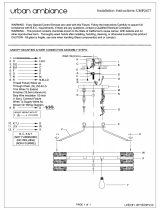
Overview
Designations:
(1)
Mounting frame
(2) Hydraulic relief
(3) Mower bar
(4) Swath former
(5) Collapsible side protection
(6) Lighting
Versions
Designation
Description
NOVACAT 352
Working width: 3,46 m
NOVACAT 402
Working width: 3,88 m
NOVACAT 442
Working width: 4,30 m
1
5
4
3
2
6

- 7 -
2000-GB-Trac
T
or requiremen
T
s_3776
EN
Trac
T
or requiremen
Tor requiremenT
T
s
TsT
Tractor
To operate this machine the following tractor requirements
are necessary:
-
Tractor power:
Novacat 352 - from 59kW/80PS
Novacat 402 - from 67KW / 90PS
Novacat 442 - from 82KW / 110PS,
-
Hitching:
Lower link Cat. III / width 3
-
Connections:
See table "Necessary hydraulic and power connections"
Ballast weights
20%
Kg
The front of the tractor must have sufficient ballast to
guarantee braking and steering capabilities.
DAN
DAN
G
ER
L
ife hazard - Steering or brake system failure due to
inadequate weight distribution between the tractor
axles.
•
Make sure that when the implement is
hitched, at least 20% of the tractor weight is
placed on the front axle.
Lifting unit (three-point linkage)
37
1-08-1
6
371-08-16
-
The tractor’s lifting unit (three-point linkage) must be
designed for the applicable load. (See technical data)
-
The lifting struts are to be set at the same length (4)
using the appropriate adjusting device
(See the tractor manufacturer’s operating manual)
-
If the lifting struts on the lower links can be fixed in
different positions, then the rear position must be
selected. This relieves the pressure on the tractor’s
hydraulic system.
-
The limiting chain or lower link stabilisers (5) are to
be set so that the attached machine CANNOT move
sideways. (Safety measure for transportation)
Hydraulic control on the lifting gear
The lifting hydraulics shall be switched on
position control:

- 8 -
2000-GB-Trac
T
or requiremen
T
s_3776
Trac
T
or requiremen
Tor requiremenT
T
s
TsT
EN
Hydraulic connections required
Design
Consumer
Single-acting
hydraulic
connection
Double-acting
hydraulic
connection
Identification
(on the
implement)
Standard
Lift-out cylinder
X
Hydraulic lower link rocker or
swivel cylinder (with active
control line)
X
Hydraulic ground pressure
system
X
Hydraulic upper link (variant)
X
Operating pressure
NOTE
M
aterial hazard - Friction wear on the piston of the control or hydraulic
block due to incompatible hydraulic oils.
•
Check the compatibility of the hydraulic oils before connecting
the implement to the hydraulic system of your tractor.
•
Do not mix mineral oils with bio oils!
Minimum operating
pressure
170 bar
Maximum operating
pressure
200 bar
Power connections required
Design
Consumer
Pin
Volt
Power connection
Standard
Lighting
7-pin
12 V DC
According to DIN-
ISO 1724

- 9 -
2000_GB-Att
A
2000_GB-AttA2000_GB-Att
chment
_3776
EN
aTT
aching
aTTaching aTT
T
o
To T
T
rac
TracT
T
or
Tor T
Attaching implement to tractor
Set lower link on tractor
-
Fix the hydraulic lower link so that the implement cannot
swing out to the side and the headstock is positioned
in the centre.
1.
Attaching machine to tractor
WARNIN
WARNIN
G
Risk of injury resulting in death or other serious injury
from driving over or rolling over a person located
between the implement and the tractor.
•
Only connect on fixed, even ground.
•
Secure the tractor against rolling before an
-
yone is allowed to enter the space between
the implement and the tractor.
CAUTION
CAUTION
Risk of crushing when bringing the tractor up to the
implement.
•
Direct everyone out of the danger area
between the tractor and the machine.
-
Connect and secure tractor lower link with the implement
lower link pins.
-Adjust the lower link bolt (1) at the support frame with the
locating screw to category 3 / width 3. The mower must
not touch the rear tractor tyres. The bolts are to be fitted
with the balls (1) on both lower links outside. (Exception:
if your tractor has the "Quick Hitch" system then the bolts
with the balls have to be fitted on the inside.)
1
Outside
Inside
Safety advice
DAN
DAN
G
ER
L
ife-threatening danger through operating a machine
that is unroadworthy or damaged
•
Check the vehicle for roadworthiness prior
to every operation (lights, brakes, protective
panels …)!
DAN
DAN
G
ER
L
ife-threatening danger through implement operation
with self-driven machines. The field of vision during
a transport journey is restricted when the device is
attached.
•
Operate the machine only with tractors
whose field of vision remains unaffected by
the unit during transport.
CAUTION
CAUTION
Risk of crushing injury caused by machines being
parked on feet.
•
Use tractor’s hydraulic lift only when no one
is standing in the danger area.
For further safety instructions see Supplement A1, pt. 7),
8a. - 8h.)

- 10 -
2000_GB-Att
A
2000_GB-AttA2000_GB-Att
chment
_3776
EN
Att
A
AttAAtt
ching to tr
A
ching to trAching to tr
ctor
NOTE
Ri sk of da ma ge to prop er t y d ue to an
implement coming loose from the tractor.
If the screw is only fixed in the bracket and does not
reach the hole in the bolt, the lateral movement of the
bolt is still possible and the mower can come loose
from the coupling.
•
Check the tight connection between screw
(2) and coupling pin.
-
Connect upper link and secure.
DAN
DAN
G
ER
L
ife-threatening danger exists when cardan shaft
length is unadapted
•
Before initial operation, check the length of
the cardan shaft and adapt if necessary.
•
A tractor change is considered to be an
initial operation.
•
See chapter "Adapting the Cardan shaft" in
Appendix B.
025-05-04
L2
-
Connect cardan shaft.
-
Connect the 7-pin plug of the lighting to the tractor.
-
Connect hydraulic hoses depending on equipment.
-
Lay control line in tractor cabin.
-
Raise support stand and secure!
2.
Set mounting frame to horizontal
Bring mounting frame into horizontal position by adjusting
hydraulic lower link rocker
- Swing the mower into the off-road transport position
-Actuate servo-valve in tractor until mounting frame is
horizontal.
3.
Adjust upper link
-
Turning upper link spindle (16) adjusts the cutting height.
TIP
A hydraulic upper link is recommended (A double acting
control unit is required for this purpose)

- 11 -
2000_GB-Att
A
2000_GB-AttA2000_GB-Att
chment
_3776
EN
Att
A
AttAAtt
ching to tr
A
ching to trAching to tr
ctor
4.
Swivel safety lever out
after assembly and before lifting in field transport position,
you must swivel out the safety flap (1)
Requirements:
-
The disc mower is mounted correctly on the tractor.
-
The single acting hydraulic implement is in floating
position.
1.
Lift the tractor hoist so far that the safety flap becomes
mobile.
2.
Swivel the safety flap from position A to position B.
Pos. A
Pos. B
1
3.
Set lifting height to 700 mm under the right lower link.
700 mm
Carry out trial run
Set lifting height
-
Lift disk mower high enough so that the cardan shaft
is horizontal.
Set power take-off r.p.m.
-
Set appropriate power take-off r.p.m. on tractor
TIP
A transfer placed near the transmission gives information
about the rpm for which the disc mower is designed.
Check rotation direction
- The power take-off rotation direction is suitable when,
looking from the front, the outer cutting discs rotate
inward.
504-12-01

- 12 -
2000_GB-Att
A
2000_GB-AttA2000_GB-Att
chment
_3776
EN
Att
A
AttAAtt
ching to tr
A
ching to trAching to tr
ctor
Set hydraulic relief
CAUTION
CAUTION
Risk of crushing injury. The mowing unit may tip
forwards during the adjustment procedure.
•
Remove anyone who is not involved from
the danger area.
Relief system control
The set mower bar hydraulic relief can be checked as follows
-
Mechanically
by lifting the cutter bar on one side. The weight should
be approx. 75 kg.
517-10-07
-
Pressure gauge
By reading the displayed value on the pressure gauge
(A display value of 100 bar is recommended)
Setting the relief
Hydraulic prestress pressure is set using a single-action
control unit. The prestress pressure can be read at the
pressure gauge
TIP
The hydraulic connection for the hydraulic relief on the
mower is fitted with a stop valve. Open this tap prior to
changing the preload pressure and close it again after
changing the pressure.
Recommended values for prestress pressure ex-works:
Manometer display
3.0m F
M
3.5m F
M
Novacat 352
80 bar
90 bar
Novacat 402
90 bar
100 bar
Novacat 442
105 bar
115 bar
FM = front mower

- 13 -
2000 GB TRANSPORT POSITION 3776
EN
Transpor
T
and
T and T
W
orking posi
Working posiW
T
ion
TionT
Safety advice
DAN
DAN
G
ER
L
ife-threatening danger through the mower tipping
over
•
Change from the working to the transport
position only on level, solid ground.
DAN
DAN
G
ER
L
ife-threatening danger through rotating or
ejected components
•
Switch off the cutter bar drive.
•
Wait until the cutter bar has stopped moving
before swivelling it up.
DAN
DAN
G
ER
L
ife-threatening danger through moving parts
•
Make sure that the swivel range is clear and
that no-one is standing in the danger area.
Changing from working position to field
transport position
Procedure:
1)
Raise the mower into field transport position using the
control unit
Changing from field transport to
transport position
NOTE
Risk of damage to cardan joint or cardan shaft
stub at the angular gear input point!
The cardan shaft may break if under brakes when
changing to the transport position.
•
Disengage the cardan shaft brake before
changing the transport position.
Procedure:
1)Turn drive off and wait for mower discs to come to a
standstill
2)
Pull control line
3)Simultaneously, use servo-valve to swivel mower to
transport position
TIP
•
If you activate the dual-action control unit
without pulling the control line, only the hori
-
zontal position of the hitch changes.
DAN
DAN
G
ER
Danger to life due to lack of visible lighting.
•
Make sure that the side protection is folded
down so that the reflective strips and lighting
are visible from behind the device.

- 14 -
2000 GB TRANSPORT POSITION 3776
Transpor
T
and working posi
T and working posiT
T
ion
TionT
EN
Changing from transport to working
position
Procedure:
1)
Pull control line
2)Simultaneously, use servo-valve to swivel mower to field
transport position until the swivel cylinder is completely
extended
TIP
•
If you activate the dual-action control unit
without pulling the control line, only the hori
-
zontal position of the hitch changes.
3)
Use control unit to lower the mower to working position.

- 15 -
2000_GB_Unhitching_3776
EN
unhi
T
ching
TchingT
and parking
ching and parkingching
General tips
DAN
DAN
G
ER
L
ife-threatening danger through tipping.
•
Make sure the machine is standing securely.
•
Park the implement only on flat, firm ground.
•
Use the support stands on the machine.
DAN
DAN
G
ER
L
ife-threatening danger exists if another person starts
up the tractor and drives away or actuates the control
lever of the hydraulic system while you are engaged
in maintenance.
•
Before carrying out maintenance and repair
work, switch off the engine and remove the
key and apply the tractor's brakes.
DAN
DAN
G
ER
L
ife-threatening danger should the tractor start
moving on its own.
•
Before carrying out maintenance and repair
work, switch off the engine and remove the
key and apply the tractor's brakes.
•
Secure the machine with chocks if neces
-
sary.
CAUTION
CAUTION
Risk of minor or moderate injury from crushing and
shearing sections of the hitching frame.
•
Do not stand between the tractor and the
device if the tractor has not been stopped
and the PTO is moving.
Unhitching implement from tractor
WARNIN
WARNIN
G
Risk of an injury resulting in death or other serious
injury due to the failure of the safety flap (1).
•
The safety lever (1) is a safety fixture. It
should not be changed in its form and
functions.
•
The safety flap is designed in such a way
that it does not jump out of the locking posi
-
tion when the cutter bar is folded up hydrau
-
lically, therefore do not actuate the hydraulic
cylinder for folding up when the safety flap is
in the locking position. (Pos. A)
•
Damaged safety flaps must be replaced
immediately with new ones.
Depending on parking situation, mower can be unhitched
in the transport position (H) or working position (R).
The following procedure applies to both situations:
1)
Swivel safety guard (1) into (Pos. A)

- 16 -
2000_GB_Unhitching_3776
UNHITCHING a
N
d park
Nd parkN
ING
d parkINGd park
EN
Pos. A
Pos. B
1
CAUTION
CAUTION
Risk of slight or moderate injury due to jerky lifting
of the mower attachment frame when uncoupling
from the lower links.
•
Check that the safety flap (1) is swivelled to
position A before uncoupling the device.
2)Extend or fold down support stands (2) and secure
2
3)Take control line from tractor cabin and place, rolled up,
on mower’s hose storage.
4)Close off hydraulic hoses and place on mower’s hose
storage.
5)Unplug tractor 7-pin lighting plug
6)Uncouple cardan shaft and lay on cardan shaft holder.
7)Uncouple upper link
8)Separate the tractor lower link arm from the machine's
lower link pin
9) Carefully drive the tractor away from the implement.

- 17 -
2000-EN I
N
s
E
rt 3776
EN
o
pera
T
ion
TionT
Safety advice
DAN
DAN
G
ER
L
ife-threatening danger exists through blades being
ejected.
•
After the first operating hours tighten all
blade screwed connections.
•
Check all safety equipment before starting
work. In particular, make sure that the side
safeguards are folded down correctly in the
field transport position.
DAN
DAN
G
ER
L
ife-threatening danger exists through ejected parts
when removing a blockage, when changing blades
or when adjusting the machine during operation.
•
Stop tractor/trailer unit on level ground and
apply tractor's brakes.
•
Park the mower in the working position.
•
Before going to the rear of the machine,
make sure that the PTO shaft is station
-
ery and that the hydraulic connections are
depressurised.
•
Remove the tractor key!
DAN
DAN
G
ER
L
ife-threatening danger exists through falling off
the machine.
•
Do not climb onto, play on or around the
machine.
•
Do not let anyone climb on or clamber about
on the machine.
•
Before starting, make sure that no one is
standing on the machine or in its danger
area!
TIP
Further safety instructions: see Supplement A, pt. 1. - 7.)
Important notes prior to starting work
1.
Check
-
Check the condition of blades and the blade fastening.
-
Check mowing discs for damage (see chapter
"Maintenance and Service")
2.
Only switch the machine on when in the
working position and do not exceed the
stipulated p.t.o. speed!
1000 Up
m
A transfer located near the transmission advises which
p.t.o. speed your mower unit is equipped for.
• Always,
and
only,
switch
the
p.t.o.drive
on
when
all
safety
devices (covers, protective aprons, casings, etc.) are
in proper condition and are attached to the machine in
their safety positions.
3.
Pay attention to correct
p.t.o. direction of rotation!
TD8/95/6a
4.
Prevent any damage!
NOTE
Property damage caused through unnoticed
obstacles. Obstacles (e.g. large stones, pieces
of wood, boundary stones, etc.) can damage the
mower unit
•
Inspect the field before mowing and remove
the obstacles.
•
Alternatively: Drive round obstacles at a
sufficient distance.
If a collision occurs anyway,
• Stop
immediately
and
switch
off
the
drive.
• Check
the
machine
carefully
for
any
damage
In
particular,
check the mowing discs and their drive shafts (4a).

- 18 -
2000-EN I
N
s
E
rt 3776
Operati
O
n
EN
01-00-10
01-00-10
4a
• If
necessary
have
it
checked
over
in
a
specialist
work
shop also.
After contact with a foreign object
•
Check
condition
of
blades
and
blade
fixing
(see
chapter
"Maintenance and Service").
• Retighten
all
blade
screw
fittings.
5.
K
eep a safe distance while engine is running.
bsb 447 410
• Direct
people
out
of
the
danger
area
as
they
may
become
injured by foreign objects ejected by the mower.
Special care is necessary on stony ground, and near
roads and paths.
6.
Wear hearing protection
The noise level in the workplace can deviate from the
measured value (see Technical Data) partly because
of the differing cabin types of various tractors.
• If
an
85
dB(A)
noise
level
is
reached
or
exceeded,
then
the farmer (or contractor) must provide appropriate
hearing protection (UVV
1.1 § 2).
•
If
a
noise
level
of
90
dB
(A)
is
reached
or
exceeded,
then hearing protection must be worn (UVV
1.1 § 16).
Mowing
1.
Adjust the cutting height by turning the upper
link spindle and with the hydraulic upper link
(max. 5° inclination to mower discs)
2.
To mow, slowly engage the pto outside the
mowed fodder (in field transport position) and
take the mower rotor to full speed.
Smoothly increase the p.t.o. speed, in order to avoid
noises in the free-wheel conditioned by the system.
-
Adjust travel speed to terrain and crop.
Reversing
Raise the mower when reversing!
Protective covers
The side guard and front guard can be folded up for cleaning
and maintenance work.
The two foldable guards lock mechanically in closed
condition. A tool (e.g. screwdriver) is required to open them.
DAN
DAN
G
ER
Danger to life due to parts being thrown off.
•
Move all the protective devices to their
intended positions before use.
•
Check whether the protective devices have
defects which impair their function. Replace
damaged covers before use.
•
Stones and other objects can be picked up
and ejected when mowing. Direct all per
-
sons out of the danger area.

- 19 -
2000-EN I
N
s
E
rt 3776
Operati
O
n
EN
Settings for operation
Tractor hydraulic system
-
The right lower link is to be set to H1 ≈ 700 mm ground
distance.
-
Fix the tractor hydraulic system in this position
700 mm
Headstock
Adjust the headstock to horizontal. Changes can be
performed with the hydraulic lower link compensator.
1.
Set 3-way cock at headstock downwards to select
the function "Hydraulic lower link".
2.
Activate dual-action control unit at tractor until the
hitching frame is horizontal.
-
L
ift-out cylinder
-
The lift-out cylinder control unit is to be switched to
floating position during use to achieve correct adjustment
to soil
Protective covers
-
All protective covers are closed and in proper condition

- 20 -
1301_GB-HANGFAHRT_358
GB
Working on slopes
Take care when turning on slopes!
The tractor's travelling characteristics are
influenced by the weight (
G
) of the mower
unit. This can lead to dangerous situations,
especially on slopes.
Danger of tipping occurs
- when the mower unit is facing downhill and in a raised
position,
- when travelling in a left-hand curve with the mower unit
raised,
- when travelling in a left-hand curve in the transport position
(mower unit completely raised).
Safety information
• Reduce
speed
in
left-hand
curves
accordingly.
• Travel
so
that
the
raised
mower
unit
is
facing
uphill.
• It
is
better
to
travel
in
reverse
on
a
slope
than
to
carry
out a risky turning manoeuvre.
TD15/95
/3
G
G
G
TD15/95/2
TD15/95/4
Note:
Raise the mower
when reversing!
/