
OWNER’S MANUAL
MODEL NUMBER
700300-1
BERCO
TWO STAGE 48" Snowblower
for
TRACTORS WITH 2000 R.P.M. P.T.O. DRIVE
103391 C-09
* ASSEMBLY * REPAIR PARTS
* OPERATION * MAINTENANCE
CAUTION:
READ & FOLLOW ALL SAFETY RULES & INSTRUCTIONS
BEFORE OPERATING YOUR EQUIPMENT

WARRANTY
LIMITED ONE YEAR ON BERCO TRACTOR ATTACHMENTS
For one year from date of purchase, Bercomac Limitée will repair or replace free of charge at Bercomac's option, any
parts which are defective as a result of defective materials or faulty workmanship.
COMMERCIAL OR RENTAL USE:
Warranty on Berco attachments used for commercial or rental purposes is limited to 90 days.
This warranty does NOT cover:
* Wear items, such as shear pins and belts.
* Repairs due to customer abuse or neglect.
* Pre-delivery set-up.
* In home service.
Warranty service is available by returning the "Berco" attachment to the authorized dealer.
BERCOMAC Limitée
46 Fortin N, Adstock, Québec, Canada, G0N 1S0

TABLE OF CONTENTS
INTRODUCTION ...................................................................................................................................................... 2
SAFETY PRECAUTIONS ....................................................................................................................................... 3
SAFETY DECALS .................................................................................................................................................... 5
ASSEMBLY
Step 1: Snowblower Preparation ............................................................................................................. 6
Step 2: Snowblower Installation ............................................................................................................... 8
OPERATION
Controls ....................................................................................................................................................... 10
Operating the Snowblower ........................................................................................................................ 10
Removing Snow ......................................................................................................................................... 10
Snow Removal Methods ........................................................................................................................... 11
MAINTENANCE
Maintenance ............................................................................................................................................... 12
Lubrication .................................................................................................................................................. 12
Chain Adjustment ....................................................................................................................................... 12
Shear Bolt Replacement ........................................................................................................................... 12
MAINTENANCE & DISMOUNTING
Snowblower dismounting .......................................................................................................................... 13
End of Season Storage ............................................................................................................................. 13
PARTS BREAKDOWN AND LISTS
Rotation System with Chute ...................................................................................................................... 14
Snowblower ................................................................................................................................................ 16
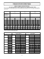
TORQUE SPECIFICATION TABLE ....................................................................................................................... 19
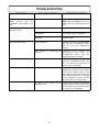
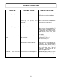
TROUBLESHOOTING ............................................................................................................................................ 20
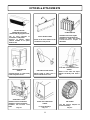
OPTIONS & ACCESSOIRES ................................................................................................................................. 22
PAGE
1

INTRODUCTION
2
TO THE PURCHASER
This new attachment was carefully designed to give years of dependable service. This manual has been provided to
assist in the safe operation and servicing of your attachment.
NOTE: All photographs and illustrations in the manual may not necessarily depict the actual models or attachment, but
are intended for reference only and are based on the latest product information available at the time of publication.
Familiarize yourself fully with the safety recommendations and operating procedures before putting the machine to use.
Carefully read, understand and follow these recommendations and insist that they be followed by those who will use
this attachment.
THIS SAFETY ALERT SYMBOL IDENTIFIES AN IMPORTANT SAFETY MESSAGE IN THIS MANUAL
THAT HELPS YOU AND OTHERS AVOID PERSONAL INJURY OR EVEN DEATH. DANGER,
WARNING, AND CAUTION ARE SIGNAL WORDS USED TO IDENTIFY THE LEVEL OF HAZARD.
HOWEVER, REGARDLESS OF THE HAZARD, BE EXTREMELY CAREFUL.
DANGER: Signals an extreme hazard that will cause serious injury or death if recommended precautions are
not followed.
WARNING: Signals a hazard that may cause serious injury or death if the recommended precautions are not
followed.
CAUTION: Signals a hazard that may cause minor or moderate injury if the recommended precautions are not
followed.
Record your attachment serial number and purchase date in the section reserved below (there is no serial number on
the subframe). Your dealer requires this information to give you prompt, efficient service when ordering replacement
parts. Use only genuine parts when replacements are required.
If warranty repairs are required please present this registration booklet and original sales invoice to your selling dealer
for warranty service.
This manual should be kept for future reference.
7
SERIAL NUMBER : ___________________________
PURCHASE DATE : ___________________________
In this manual, right and left sides are determined by sitting on the tractor seat facing forward.
In this manual, "attachment" means accessories that you install on the tractor, such as, snowblower, rotary
broom, blade, rotary tiller, cab, subframe, etc...

SAFETY PRECAUTIONS
Careful operation is your best insurance against an accident. Read this section carefully before operating the tractor
and snowblower. All operators, no matter how experienced they may be, should read this and other manuals related
to the tractor and snowblower before operating. It is the owner's legal obligation to instruct all operators in safe
operation.
TRAINING
This symbol, "Safety Alert Symbol", is used
throughout this manual and on the
attachment’s safety labels to warn of the
possibility of personal injury. Please take
special care in reading and understanding the
safety precautions before operating the
attachment or the tractor.
1. Read this owner's manual carefully. Be thoroughly
familiar with the controls and proper use of the
snowblower. Know how to stop the unit and
disengage the controls quickly.
2. Never allow children to operate snowblower.
Never allow adults to operate snowblower without
proper instructions.
3. No one should operate the unit while intoxicated or
while taking medication that impairs the senses or
reactions.
4. Keep the area of operation clear of all persons,
particularly small children and pets.
PREPARATION
1. Thoroughly inspect the area where the
snowblower is to be used and remove door mats,
all foreign objects and the like.
2. Disengage all clutches and shift into neutral before
starting engine.
3. Do not operate the snowblower without wearing
adequate winter outer garments. Wear footwear
that will improve footing on slippery surfaces.
4. Handle fuel with care, it is highly flammable.
a) Use approved fuel container.
b) Never add fuel to a running engine or hot
engine.
c) Fill fuel tank outdoors with extreme care.
Never fill fuel tank indoors.
d) Replace fuel cap securely and wipe up spilled
fuel.
5. Adjust the height of the snowblower to clear
gravel or crushed rock surface.
7
3
6. Never attempt to make any adjustments while
the engine (motor) is running (except when
specifically recommended by manufacturer).
7. Let engine (motor), tractor and snowblower
adjust to outdoor temperatures before starting to
clear snow.
8. Always wear safety glasses or eye shields during
operation or while performing an adjustment or
repair to protect eyes from foreign objects that
may be thrown from the machine.
OPERATION
1. Do not put hands or feet near or under rotating
parts. Keep clear of the discharge opening at all
times.
2. Exercise extreme caution when operating on or
crossing gravel drives, walks, or roads. Stay alert
for hidden hazards or traffic. Do not carry
passengers.
3. After striking a foreign object, stop the engine
(motor), disconnect the wire from the spark plug
(s) and keep wire away to prevent accidental
starting. Thoroughly inspect the snowblower for
any damage and repair damage before restarting
and operating the snowblower.
4. If the unit should start to vibrate abnormally, stop
the engine (motor) and check immediately for the
cause. Vibration is generally a warning of
trouble.
5. Stop the engine (motor) whenever you leave the
operating position.
6. Take all possible precautions when leaving the
machine unattended. Disengage the power take-
off, lower the attachment, set the parking brake,
stop the engine and remove the key.
7. When cleaning, unclogging, repairing or
inspecting, make certain the collector/impeller
and all moving parts have stopped. Disconnect
wire from the spark plug(s) and keep wire away
to prevent accidental starting.

SAFETY PRECAUTIONS
8. Do not run the engine indoors, except when
starting the engine and for transporting the
snowblower in or out of the building. Do not
operate or let motor run in a storage area without
ventilation because gas contains carbon
monoxide which is odourless, colorless and can
cause death.
9. Do not clear snow across the face of slopes.
Exercise extreme caution when changing direction
on slopes. Do not attempt to clear steep slopes.
10. Never operate the snowblower without proper
guards, plates, or other safety protective devices
in place
11. Never operate the snowblower near glass en-
closures, automobiles, window wells, drop-offs,
and the like without proper adjustment of the snow
discharge angle. Keep children and pets away.
12. Do not overload the machine capacity by
attempting to clear snow at too fast a rate.
13. Never operate the snowblower at high transport
speeds on slippery surfaces. Use care when
backing.
14. Never direct discharge at bystanders or allow
anyone in the clearance area.
15. Disengage power to the collector/impeller when
the snowblower is transported or not in use.
16. Use only the attachments and accessories
approved by the manufacturer of the tractor (such
as wheel chains, counterweights, cabs and the
like).
17. Never operate the snowblower without good
visibility or light.
MAINTENANCE AND STORAGE
1. Check shear bolts, engine mounting bolts, and
other bolts at frequent intervals for proper
tightness to be sure the snowblower is in safe
working condition.
2. Never store the machine with fuel in the fuel tank
inside a building where ignition sources are
present such as hot water and space heaters,
clothes dryers, and the like. Allow the engine to
cool before storing in any enclosure.
3. Always refer to the operator's guide instructions
when you store the snowblower.
4. Maintain or replace safety and instruction labels,
as necessary.
5. Run the snowblower a few minutes after
throwing snow to prevent freeze-up of the collector/
impeller
4
WHENEVER YOU SEE THIS SYMBOL
7
IT MEANS:
WARNING!
BECOME ALERT !
YOUR SAFETY IS INVOLVED!

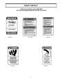
SAFETY DECALS
5
REPLACE IF DECALS ARE DAMAGED
SEE PARTS BREAKDOWN FOR DECAL LOCATION
#102113 #102125 #102124
#102126 #102127

ASSEMBLY
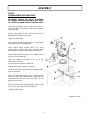
STEP 1
SNOWBLOWER PREPARATION:
IMPORTANT: TORQUE ALL BOLTS ACCORDING
TO TORQUE SPECIFICATION TABLE (SEE TABLE
OF CONTENTS), WHEN STATED: TIGHTEN FIRMLY.
Install the hand guard (item 1) on the chute (item 2)
as shown with the top portion inside and the bottom
portion outside.
Secure in place with two 1/4 x 3/4" bolts (item 3), the
flat washers and flange nuts inside.
Tighten the bolts firmly.
Insert shortest plastic bushing (item 6) in the welded
tube at the back of the snowblower.
Insert longest plastic bushing (item 7) in worm
support (item 4), grease both ends of rotation worm
and insert the bushing on the rotation worm (item 8) .
Install rotation worm assembly in the welded tube at
the back of the snowblower.
Place the rotation ring (item 5) on top of the
snowblower as shown.
Only one position provides a perfect fit.
Apply grease on the rotation ring (item 5).
Install the chute (item 2) with the four retaining plates
(item 9) as shown.
At the rear left hand corner, secure a retaining plate
(item 9) on top and the rotation worm support (item 4)
underneath with two 1/4 x 3/4" bolts (item 11) and
flange nuts as shown.
Secure the other three retaining plates (item 9) with
six 1/4 x 1/2" bolts (item 10) and flange nuts.
Tighten the bolts firmly.
6
Prepare the chute

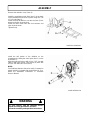
ASSEMBLY
Remove the reduction cover ( item 4).
Install the snowblower male hitch (item 1) in the back
of the snowblower and secure in place using four 7/16
x 1 1/4’’ bolts (item 2).
Install one bolt, flat washer, over the slot (item 3) lock
washer and nylon insert locknut.
Install the other three bolts with lock washers and
nylon insert locknuts.
Tighten firmly.
Install the half portion of the driveline on the
snowblower by sliding the round yoke (item 1) on the
shaft (item 5).
Align the holes and secure with a 1/4 x 2 1/2’’ hex bolt
(item 2) and nylon locknut. Lock the key in place with
an 3/8 x 3/8" allen set screw (item 4).
NOTE:
See Subframe Owner’s Manual to verify if a extension
guard (shield) is included with the driveline kit. If so,
follow the installation instructions in subframe
Owner’s Manual.
7
Install the snowblower
Install half drive line
7 WARNING 7
For your security, read the subframe owner's
manual for safety precautions and rules.
Follow the assembly and operation instructions.

ASSEMBLY
Install the tractor’s section of driveline into the
snowblower’s driveline by aligning the stamped marks
(item 2) (located between the splines at the end of the
shaft) with the large groove (item 1) in the hollow tube
on the snowblower’s section.
Only one position allows the sections to be inserted
one into the other.
Attach the snowblower to the subframe by inserting
the snowblower’s male hitch (item 2) into the pivot
support (item 3). Make sure the male hitch is entered
to its maximum and locked in place by the springs
(item 1).
Connect the rotary driveline to the tractor P.T.O.
spline shaft.
Make sure the driveline yoke is securely attached
to the tractor P.T.O.
Install the reduction cover (item 8) with the extension
guard (not shown) in place and secure with the rubber
latch.
Install 1/2 x 3’’ handgrip (item 1) on the handle (item
3).
Insert the handle through the grommet in rotation
support (item 2).
Install the handle extension (item 7) (included with the
subframe) in the rotation handle (item 3) with a 2.5
mm hair pin (item 6).
Install the handle hook (item 4) on rotation worm (item
5). Insert hook in handle and lock in place with a 2.5
mm hair pin (item 6).
STEP 2
SNOWBLOWER INSTALLATION:
7 WARNING 7
TO PREVENT INJURIES:
Stop the motor.
Apply parking brakes.
Remove the ignition key.
Disconnect the wire from the spark plug(s) and
keep away from spark plug(s) to prevent accidental
starting.
Install the snowblower
Install the handle
Install the drive line sections
8

ASSEMBLY
9
7 DANGER 7
ROTATING DRIVELINE
Contact can cause death.
KEEP AWAY
Do not operate without:
All driveline, tractor & equipment shields in
place.
Driveline securely attached at both ends.
7 DANGER 7
If the driveline is not completely covered, be sure
a guard extension is installed.
Do not operate without driveline completely
covered by the shield.
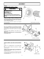
Adjust skid shoes
7 WARNING 7
To prevent injuries and for more traction when
using an attachment:
Rear counterweights of 100 lbs. minimum are
required to counter-balance attachment’s
weight.
Tractor manufacturer approved tire chains are
required.
Do not operate on slopes greater than 10°.
When dismounting an attachment remove rear
counterweights.
VERIFY SKID SHOE ADJUSTMENT:
LEVEL PAVED SURFACE: Adjust skid shoes to
allow 3/16 to 1/4" clearance (A) between cutting edge
and surface.
UNEVEN OR GRAVEL SURFACE: Adjust skid shoes
to allow 1/2 to 5/8" clearance (A) between cutting
edge and surface.
VERIFY TIRE PRESSURE:
Attachments should raise 3" to 4" above the ground
(no more, no less) if not, check and adjust tractor tire
pressure as follows:
Front tires: 20-25 psi
Back tires: 8-10 psi
Tire pressure must be even on both sides of the
tractor.

OPERATION
CONTROLS
CHUTE ROTATION
The chute rotation handle (fig.6, item 2) is located to the
left of steering wheel. Turning the handle in a clockwise
direction, turns the discharge chute in a clockwise
direction.
CHUTE DEFLECTOR
Set the angle of the deflector according to the distance
the snow must be blown and to prevent property
damage. To change the deflector angle, loosen the two
deflector knobs & adjust the deflectors to the
appropriate angle and retighten the two knobs securely.
10
7 WARNING 7
Do not attempt to clear plugged chute, auger or
fan of snow while tractor engine is running.
-Disengage snowblower.
-Lower snowblower onto ground.
-Set the parking brake.
-Stop engine, remove the ignition key, disconnect
the wire from spark plug(s) and keep away from
spark plug(s) to prevent accidental starting.
-Make sure all moving parts have stopped.
-Do not use hand to unplug chute.
-Use a 36’’ (924 mm.) minimum length stick or
board.
7 WARNING 7
Read the tractor Owner’s Manual carefully. Be
thoroughly familiar with the controls & proper
use of the equipment. Know how to stop the unit
& disengage the controls quickly.
OPERATING THE SNOWBLOWER
a) Make sure the snowblower is clear of snow before
engaging the snowblower.
b) Make sure that the auger and impeller operate
freely.
c) Start the tractor engine.
d) Before engaging the snowblower drive, always
have the engine running at medium R.P.M.
e) Operate the snowblower at maximum engine
R.P.M.
REMOVING SNOW
When removing snow, do not use the snowblower as
a dozer blade to push snow. Allow snowblower to
ingest snow at its own speed. If the speed of your
tractor is too fast, the snowblower may become
overloaded and plug. For best results, raise the
snowblower and remove a top layer of snow. A
second pass with the snowblower will remove the
remaining snow.
IMPORTANT:
Use full engine R.P.M. when removing wet, sticky
snow. Low R.P.M. power will tend to plug the
chute

OPERATION
Where it is possible to throw the snow to the left and
right (see above), as in a long driveway, it is
advantageous to start in the middle.
Blow from one end to the other, throwing snow to both
sides without changing the direction of the discharge
chute.
If the snow can only be thrown to one side of the
driveway or sidewalk (see above), start on the opposite
side.
At the end of the first pass, rotate the discharge chute
180° to maintain the direction of throw in the same area.
11
SNOW REMOVAL METHODS
A definite pattern of operation is required to thoroughly clear the snow area. These patterns will avoid blowing snow in
unwanted places as well as eliminating a second removal of snow.

MAINTENANCE
MAINTENANCE
Check mounting bolts at frequent intervals for proper
tightness to be sure that equipment is in proper working
conditions.
LUBRICATION
Drive Chains: Lubricate with chain saw chain lubricant
every 4 hours of operation and at the end of each
operation.
Chute Rotation System: Oil chute base, rotation worm
bushings and rotation hook every 8 hours of operation.
Rotary driveline: Lubricate the rotary driveline joints
every 8 hours of operation and the splines so that they
slide easily into each other every 16 hours of operation.
CHAIN ADJUSTMENT
Main Chain Drive:
Remove cover (see snowblower head, item 44) and
loosen the four flange nuts which retain the reduction
box (item 38). Set chain tension leaving 1/4" deflection
in longest chain span by screwing the tension bolts.
Tighten bolts & nuts securely.
Re-install the chain guard cover.
12
SHEAR BOLT REPLACEMENT:
Fan Shear Bolt Replacement:
The fan is protected by a shear bolt (for identification
see parts list (Snowblower head, item 20). If a foreign
object is hit, the snowblower is designed so the shear
bolt will shear to avoid damage to the snowblower.
Replace with original part (Part # 103184). The use of
any other bolt may void the warranty.
Auger Shear Bolt Replacement:
The auger is protected by a shear bolt (for identification
see parts list (Snowblower head, item 22). If a foreign
object is hit, the snowblower is designed so the bolt will
shear to avoid damage to the snowblower. Replace with
original part (Part # 103088). The use of any other bolt
may void the warranty.
To remove the damaged auger shear bolt:
The hole (situated directly to the right of the shear bolt)
is used as an alignment guide. Turn the rotary driveline
until the holes are aligned and push the part of the shear
bolt that is still in the hole. Reinstall a new bolt and
secure with a nut.
7 WARNING 7
TO PREVENT INJURIES:
Stop the motor.
Apply parking brakes.
Remove the ignition key.
Disconnect the wire from the spark plug(s) and
keep away from spark plug(s) to prevent accidental
starting.

MAINTENANCE & DISMOUNTING
DISMOUNTING
SNOWBLOWER DISMOUNTING
a) Select a level surface, set parking brake, stop the
engine, remove the ignition key and remove wire
from the spark plug(s) and keep away from spark
plug to prevent accidental starting.
b) Remove hairpin from handle tube and remove
handle.
c) Disconnect the driveline from tractor’s P.T.O. by
sliding back the collar on the yoke then pull the
driveline out.
d) Detach the snowblower by lifting up the spring
locks on quick hitch and pulling back the
snowblower.
SUBFRAME DISMOUNTING
See the subframe owner's manual for dismounting
instructions.
END OF SEASON STORAGE
a) Clean snowblower and subframe thoroughly and
repair all parts from which paint has worn.
b) List the replacement parts that will be needed before
using again.
c) Store the snowblower and the subframe in a dry
place.
13

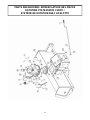
PARTS BREAKDOWN / NOMENCLATURE DES PIÈCES
ROTATION SYSTEM WITH CHUTE /
SYSTÈME DE ROTATION AVEC GOULOTTE
14

Ref. English description Description française Qty. Part #
1 Chute Goulotte 1 102058
2 Knob Bouton 2 102020
3 Nylon flat washer 11/32" Rondelle plate de nylon 11/32" 2 102009
4 Nylon flat washer 7/16" Rondelle plate de nylon 7/16" 2 102011
5 Carriage bolt 5/16" n.c. x 3/4" Boulon à carrosserie 5/16" n.c. x 3/4" 2 O/L
6 Hand guard Fourche protectrice 1 102012
7 Flat washer 5/16" hole Rondelle plate 5/16" trou 2 O/L
8 Flange nut 1/4" n.c. Écrou à bride 1/4" n.c. 10 O/L
9 Retaining plate Plaque de retenue 4 102007
10 Hex. bolt 1/4" n.c. x 1/2" Boulon hex. 1/4" n.c. x 1/2" 6 O/L
11 Hex. bolt 1/4" n.c. x 3/4" Boulon hex. 1/4" n.c. x 3/4" 4 O/L
12 Worm support Support de spirale 1 102014
13 Rotation ring Anneau de rotation 1 102016
14 Rotation bushing Coussinet de rotation 1 102060
15 Rotation worm Spirale de rotation 1 102005
16 Rotation bushing Coussinet de rotation 1 102059
17 Handle Manivelle 1 102061
18 Hand grip Poignée 1 102062
19 Handle hook Crochet de manivelle 1 102006
20 Hair pin 2.5 mm Goupille à ressort 2.5 mm 1 102013
21 Warning decal Décalque attention 1 102125
22 Danger decal Décalque danger 1 102127
23 Frame 48" Châssis 48" 1 REF
PARTS LIST / LISTE DES PIÈCES
O/L = Obtain locally/obtenir localement
15

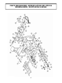
PARTS BREAKDOWN / NOMENCLATURE DES PIÈCES
SNOWBLOWER / SOUFFLEUSE À NEIGE
16

Ref. English description Description française Qty. Part #
1 Frame 48" Chassis 48" 1 103330
2 Gear box Boite d'engrenage 1 102091
3 Hex. bolt 3/8" n.c. x 4" Boulon hex. 3/8" n.c. x 4" 3 O/L
4 Flange nut 3/8" n.c. Écrou à bride 3/8" n.c. 7 O/L
5 Fan Éventail 1 102001
6 Key 8 x 7 x 35 mm Clé 8 x 7 x 35 mm 1 102035
7 Hex. bolt 8 mm x 1.25 x 25 mm Boulon hex. 8 mm x 1.25 x 25 mm 1 O/L
8 Lock washer 5/16" Rondelle de blocage 5/16" 1 O/L
9 Flat washer 3/8" hole Rondelle plate 3/8" trou 1 O/L
10 Auger 48" Vis 48" 1 103200
11 Bearing 1" w/set screw Roulement 1" a/vis à pression 4 102755
12 Hex. bolt 5/16" n.c. x 3/4" Boulon hex. 5/16" n.c. x 3/4" 2 O/L
13 Flange nut 5/16" n.c. Écrou à bride 5/16" n.c. 14 O/L
14 Sprocket Pignon 1 102921
15 Bearing 6005-2RS Roulement 6005-2RS 1 102095
16 Shear sleeve Douille de cisaillement 1 103312
17 Hex. socket set screw 5/16" n.c. x 5/16" Vis à pression hex. 5/16" n.c. x 5/16" 4 O/L
18 Shear plate Plaque de cisaillement 1 103183
19 Key 8 x 7 x 25 mm Clé 8 x 7 x 25 mm 2 102030
20 Shear bolt /N.I.L.N. (fan) pkg-10 Boulon de séc. /É.G.N. (évent.) pqt-10 1 103184
21 Drive shaft 48" Arbre de commande 48" 1 103335
22 Shear bolt /N.I.L.N.T. (auger) pkg-10 Boulon de séc. /É.G.N.M. (vis) pqt-10 1 103088
23 Flangette Flangette 2 102212
24 Tapping screw 1/4" n.c. x 1/2" Vis taraudeuse 1/4" n.c. x 1/2" 2 O/L
25 Chain roller #40 x 92 links / connecting link Chaine #40 x 92 mailles/avec maille d'accoup. 1 102022
26 Connecting Link #40 Maille d'accouplement #40 1 102040
27 Retaining bar Barre de retenue 1 103189
28 Carriage bolt 5/16" n.c. x 3/4" Boulon à carrosserie 5/16" n.c. x 3/4" 18 O/L
29 Chain guard Garde-chaine 1 102041
30 Hex. bolt 3/8" n.c. x 2" Boulon hex. 3/8" n.c. x 2" 1 O/L
31 Nylon insert lock nut 3/8" n.c. Écrou à garniture de nylon 3/8" n.c. 1 O/L
32 Hex. bolt 3/8" n.c. x 3/4" Boulon hex. 3/8" n.c. x 3/4" 4 O/L
33 Chain roller #40 x 38 link / connecting link Chaine #40 x 38 mailles/avec maille d'accoup. 1 102924
34 Input shaft Arbre d'entré 1 102148
35 Key 1/4" x 1/4" x 2" Clé 1/4" x 1/4" x 2" 1 102922
PARTS LIST / LISTE DES PIÈCES
O/L = Obtain locally/obtenir localement
17

Ref. English description Description française Qty. Part #
36 Sprocket w/set screw Pignon a/vis à pression 1 102917
37 Flangette Flangette 4 102213
38 Reduction box Boite de réduction 1 103186
39 Half teles. driveline w/set screw Demi arbre a cardan a/vis à pression 1 102898
40 Cutting edge Racloir 1 103187
41 Stover lock nut 5/16" n.c. Ecrou de blocage 5/16" n.c. 6 O/L
42 Skid shoe Patin 2 103188
43 Male hitch Attache male 1 102911
44 Reduction cover Couvercle de l'entraînement 1 102926
45 Nylon insert lock nut 5/16" n.c. Écrou à garniture de nylon 5/16" n.c. 2 O/L
46 Rubber Latch Attache en caoutchouc 1 102547
47 Hex. bolt 1/4" n.c. x 2" Boulon hex. 1/4" n.c. x 2" 1 O/L
48 Spring Ressort 1 103291
49 Tensioner Tensionneur 1 103289
50 Hex. bolt 7/16" n.c. x 1 1/4" Boulon hex. 7/16" n.c. x 1 1/4" 4 O/L
51 Lock washer 7/16" Rondelle de blocage 7/16" 4 O/L
52 Nylon Insert Lock nut 7/16" n.c. Écrou à garniture de nylon 7/16" n.c. 4 O/L
53 Flat washer 1/2" hole Rondelle plate 1/2" trou 1 O/L
54 Flangette Flangette 2 102680
55 Bearing 3/4" w/set screw Roulement 3/4" a/vis à pression 1 102864
56 Nylon insert lock nut 1/4" n.c. Ecrou a garniture de nylon 1/4" n.c. 1 O/L
57 Universal Joint Kit Joint universel 1 102928
58 Yoke 1" dia Fourche 1" dia 1 102929
59 Hex. bolt 5/16" n.c. x 1 3/4" Boulon hex. 5/16" n.c. x 1 3/4" 2 O/L
60 Chain guard Garde-chaine 1 102698
61 Lubricate decal Décalque lubrification 1 102129
62 Danger decal Décalque danger 2 102126
63 Warning decal Décalque attention 1 102124
64 Danger decal Décalque danger 1 102113
65 Berco decal Décalque Berco 1 102471
66 Serial number Numéro de série 1 REF
PARTS LIST / LISTE DES PIÈCES
O/L = Obtain locally/obtenir localement
18
Page is loading ...
Page is loading ...
Page is loading ...
Page is loading ...
-
 1
1
-
 2
2
-
 3
3
-
 4
4
-
 5
5
-
 6
6
-
 7
7
-
 8
8
-
 9
9
-
 10
10
-
 11
11
-
 12
12
-
 13
13
-
 14
14
-
 15
15
-
 16
16
-
 17
17
-
 18
18
-
 19
19
-
 20
20
-
 21
21
-
 22
22
-
 23
23
-
 24
24


Ask a question and I''ll find the answer in the document
Finding information in a document is now easier with AI
in other languages
- français: Bercomac 700300-1 Manuel utilisateur
Related papers
-
Bercomac 700416 User manual
-
-
-
-
-
-
-
-
-