Rosemount 3051HT Hygienic Pressure Transmitter Quick start guide

Type
Quick start guide
Quick Start Guide
00825-0100-4091, Rev DD
October2023
Rosemount 3051HT Hygienic
Pressure Transmitter
with 4–20 mA HART®
Contents
About this guide...........................................................................................................................3
Transmitter installation...............................................................................................................5
Product certifications................................................................................................................ 19
Quick Start Guide October2023
2 Emerson.com/Rosemount
1  About this guide
This guide provides basic guidelines for Rosemount 3051HT
Hygienic Pressure Transmitter. It does not provide instructions for
configuration, diagnostics, maintenance, service, troubleshooting,
explosion-proof, flameproof, or Intrinsically Safe (IS) installations.
Refer to the Rosemount 3051 Pressure Transmitter Manual for more
instructions. This guide and the referenced manual are also available
on Emerson.com.
1.1  Safety messages
WARNING
Explosions
Explosions could result in death or serious injury.
Installation of device in an explosive environment must be in
accordance with appropriate local, national, and international
standards, codes, and practices. Review Product certifications for
any restrictions associated with a safe installation.
Before connecting a handheld communicator in an explosive
atmosphere, ensure that the instruments are installed in
accordance with intrinsically safe or non-incendive field wiring
practices.
In an explosionproof/flameproof installation, do not remove the
transmitter covers when power is applied to the transmitter.
WARNING
Process leaks
Process leaks may cause harm or result in death.
To avoid process leaks, only use the O-ring designed to seal with
the corresponding flange adapter.
WARNING
Electrical shock
Electrical shock can result in death or serious injury.
Avoid contact with the leads and terminals. High voltage that may
be present on leads can cause electrical shock.
October2023 Quick Start Guide
Quick Start Guide 3
WARNING
Physical access
Unauthorized personnel may potentially cause significant damage to
and/or misconfiguration of end users’ equipment. This could be
intentional or unintentional and needs to be protected against.
Physical security is an important part of any security program and
fundamental in protecting your system. Restrict physical access by
unauthorized personnel to protect end users’ assets. This is true for
all systems used within the facility.
NOTICE
Conduit/cable entries
Unless otherwise marked, the conduit/cable entries in the housing
enclosure use a ½–14 NPT form. Only use plugs, adapters, glands, or
conduit with a compatible thread form when closing these entries.
Entries marked “M20” are M20 × 1.5 thread form. On devices with
multiple conduit entries, all entries will have the same thread form.
When installing in a hazardous location, use only appropriately listed
or Ex certified plugs, glands, or adapters in cable/conduit entries.
Quick Start Guide October2023
4 Emerson.com/Rosemount
2  Transmitter installation
2.1  Mount the transmitter
Before mounting, place the Rosemount 3051HT Hygienic Pressure
Transmitter to the desired orientation. When changing the
transmitter orientation, do not have the transmitter securely
mounted or clamped in place.
Conduit entry orientation
When installing a Rosemount 3051HT, Emerson recommends
installing it so that a conduit entry faces downward or parallel to the
ground. This is to maximize drainability when cleaning.
Environmental seal for housing
Thread sealing (PTFE) tape or paste on male threads of conduit is
required to provide a watertight/dustproof conduit seal and meet
requirements of NEMA® Type 4X, IP66, IP68, and IP69K. If other
Ingress Protection ratings are required, then consult the factory .
Note
IP69K rating only available on units with a Stainless Steel (SST)
housing and option code V9 in the model string.
For M20 threads, install conduit plugs to full thread engagement or
until mechanical resistance is met.
Inline gauge transmitter orientation
The low side pressure port (atmospheric reference) on the inline
gauge transmitter is located on the neck of the transmitter via a
protected gauge vent (See Figure 2-1).
Mount the transmitter so that the process can drain away. This will
keep the vent path free from obstructions including, but not limited
to, paint, dust, and viscous fluids.
October2023 Quick Start Guide
Quick Start Guide 5
Figure 2-1: Inline protected gauge vent low side pressure port
Aluminum Polished 316 SST
A. Low side pressure port (atmospheric reference)
Clamping
When installing a clamp, follow the recommended torque values
provided by the gasket manufacturer.
Note
To maintain performance, Emerson does not recommend torquing a
1.5" Tri-Clamp beyond 50 in-lb. on pressure ranges below 20 psi.
2.2  Set the switches
Before installation, set alarm and security switch configuration as
shown in Figure 2-2 and Figure 2-3.
The alarm switch sets the analog output alarm to high or low.
Default alarm is high.
The security switch allows ( ) or prevents ( ) any configuration of
the transmitter. Default security is off ( ).
To change the switch configuration:
Procedure
1. If the transmitter is installed, then secure the loop.
2. Remove power.
3. Remove the housing cover opposite the field terminal side.
Quick Start Guide October2023
6 Emerson.com/Rosemount
WARNING
When the circuit is live in explosive atmospheres, do not
remove the instrument cover.
4. Using a small screwdriver, slide the security and alarm
switches into the preferred position.
5. Reattach the transmitter cover.
Note
To comply with:
Applicable ordinary location requirements, the covers must
only be capable of being released or removed with the aid of a
tool.
Explosion-proof requirements, the cover must be fully
engaged.
Figure 2-2: Transmitter electronics board - aluminum
Without LCD display With Local Operator Interface
(LOI) or LCD display
A. Alarm
B. Security
October2023 Quick Start Guide
Quick Start Guide 7
Figure 2-3: Transmitter electronics board - polished 316
Stainless Steel (SST)
Without LCD display With LOI or LCD display
A. Alarm
B. Security
2.3  Connect the wiring and power up
Figure 2-4: Transmitter wiring diagrams (4–20 mA) - aluminum
DP
A
B
D
E
C
A. Minimize distance
B. Trim shield and insulate
C. Protective grounding terminal
D. Insulate shield
E. Connect shield back to the power supply ground
Quick Start Guide October2023
8 Emerson.com/Rosemount
Figure 2-5: Transmitter wiring diagrams (4–20 mA) - polished 316
Stainless Steel (SST)
DP
A
B
D
E
C
A. Minimize distance
B. Trim shield and insulate
C. Protective grounding terminal
D. Insulate shield
E. Connect shield back to the power supply ground
Note
Use shielded twisted pair cables for best results.
Use 24 AWG or larger wire that does not exceed 5,000 ft. (1,500 m) in
length.
If applicable, install wiring with a drip loop. Arrange the drip loop so
the bottom is lower than the conduit connections and the transmitter
housing.
NOTICE
Installation of the transient protection terminal block does not
provide transient protection unless the Rosemount 3051HT
Hygienic Pressure Transmitter case is properly grounded.
Do not run signal wiring in conduit or open trays with power
wiring, or near heavy electrical equipment.
Do not connect the powered signal wiring to the test terminals.
Power could damage the test diode in the terminal block.
October2023 Quick Start Guide
Quick Start Guide 9
Procedure
1. Remove the housing cover on the FIELD TERMINALS side.
2. Connect the positive lead to the “+” terminal (PWR/COMM) and
the negative lead to the “” terminal.
3. Ensure full contact with terminal block screw and washer.
When using a direct wiring method, wrap wire clockwise to
ensure it is in place when tightening the terminal block screw.
NOTICE
Emerson does not recommend using a pin or a ferrule wire
terminal, as the connection may be more susceptible to
loosening over time or under vibration.
4. Ground housing to fulfill local grounding regulations.
Ensure proper grounding. It is important that the instrument
cable shield be:
Trimmed close and insulated from touching the transmitter
housing.
Connected to the next shield if cable is routed through a
junction box.
Connected to a good earth ground at the power supply
end.
Note
If transient protection is needed, then refer to Grounding for
transient terminal block for grounding instructions.
5. Plug and seal unused conduit connections.
6. Reattach the transmitter covers.
Note
To comply with applicable ordinary locations requirements, the
covers must only be capable of being released or removed with the
aid of a tool.
To comply with explosion-proof requirements, the cover must be fully
engaged.
Quick Start Guide October2023
10 Emerson.com/Rosemount
Figure 2-6: Wiring considerations
Aluminum Polished 316 SST
DP
A
B
D
E
C
DP
A
B
D
E
C
A. Minimize distance
B. Trim shield and insulate
C. Protective grounding terminal
D. Insulate shield
E. Connect shield back to the power supply ground
Note
Do not ground cable shield at the transmitter.
2.3.1  Grounding for transient terminal block
Ground termination is provided on the outside of the electronics
housing and inside the terminal compartment. These grounds are
used when the transient protection terminal blocks are installed.
Emerson recommends using 18 AWG or larger wire to connect
housing ground to earth ground (internal or external).
If the transmitter is currently not wired for power up and
communication, follow Connect the wiring and power up. When the
transmitter is properly wired, refer to Figure 2-6 for internal and
external transient grounding locations.
NOTICE
The Rosemount 3051HT polished 316 Stainless Steel (SST) housing
only provides ground termination inside the terminal compartment.
October2023 Quick Start Guide
Quick Start Guide 11
2.4  Configuration parameters
Emerson recommends that you verify various configuration
parameters prior to installing the transmitter into the process:
Alarm and saturation levels
Damping
Process variables
Range values
Tag
Transfer function
Units
Complete the following procedural steps to verify these parameters.
See Figure 2-7 for a full menu tree.
NOTICE
Emerson recommends installing the latest DD to ensure full
functionality. Download the latest DD at Software Downloads &
Drivers | Emerson US.
Procedure
1. Set alarm and saturation values: Device SettingsSetup
OverviewAlarm and Saturation Values.
2. Set damping: Device SettingsSetup OverviewOutput.
3. Set process variables:
Primary variable: Device SettingsSetup Overview
Output
Secondary/Tertiary/Quaternary variables: Device Settings
CommunicationHARTVariable Mapping
4. Set range values: Device SettingsSetup OverviewOutput.
5. Set tag: Device SettingsSetup OverviewDevice.
6. Set transfer function: Device SettingsSetup Overview
Output.
7. Set units:
Pressure units: Device SettingsSetup Overview
Output
Other units: Device SettingsOutputPressure/Flow/
Totalizer/Level/Volume/Module TemperatureSetup
Quick Start Guide October2023
12 Emerson.com/Rosemount
Figure 2-7: Device driver (DD) menu tree
2.4.1  Wireless configuration via Bluetooth® technology
Download AMS Device Configurator
Procedure
Download and install the app from your app store.
Note
The first time opening AMS Device Configurator, you may be asked
to allow the application to access media on your device and to access
your device's location. If prompted, select Allow.
October2023 Quick Start Guide
Quick Start Guide 13
Related information
Emerson.com/Automation-Solutions-Bluetooth
2.4.2  Configure via Bluetooth® wireless technology
Procedure
1. Launch AMS Device Configurator.
See AMS Device Configurator for Emerson Field Devices.
2. Select the device where you want to connect.
3. On first connection, enter the key for selected device.
4. At the top left, select the menu icon to navigate the desired
device menu.
Bluetooth® UID and key
You can find the Unique Identifier (UID) and key on the disposable
paper tag attached to:
the device
the terminal block cover
and on the display unit
Figure 2-8: Bluetooth security information
2.5  Trim the transmitter
Devices are calibrated by the factory. Once installed, it is
recommended to perform a zero trim on gauge transmitter to
eliminate error due to mounting position or static pressure effects.
Quick Start Guide October2023
14 Emerson.com/Rosemount
A zero trim can be performed using either a Field Communicator or
configuration buttons.
CAUTION
It is not recommended to zero an absolute transmitter, Rosemount
3051HTA Transmitter.
Note
When performing a zero trim, ensure no process pressure is applied
to device and all wet legs are filled to the correct level.
Procedure
Choose your trim procedure:
a) Analog zero trim – Sets the analog output to 4 mA.
Also referred to as a “rerange” it sets the Lower Range
Value (LRV) equal to the measured pressure.
The display and digital HART® output remains unchanged.
b) Digital zero trim – Recalibrates the sensor zero.
The LRV is unaffected. The pressure value will be zero (on
display and HART output). 4 mA point may not be at zero.
This requires the factory calibrated zero pressure is within
a range of 3% of the URL [0 ± 3% × URL].
URV = 250 inH2O
Note
Applied Zero Pressure = ± 0.03 × 250 inH2O = ± 7.5 inH2O (compared
to factory settings) values outside this range will be rejected by the
transmitter.
2.5.1  Trimming with a Field Communicator
Procedure
1. Connect the Field Communicator. For instructions, see
Connect the wiring and power up.
2. Follow the HART® menu to perform the desired zero trim.
October2023 Quick Start Guide
Quick Start Guide 15
Table 2-1: Zero Trim Fast Keys
Analog Zero (Set 4 mA) Digital Zero
Fast Key
sequence
3, 4, 2 3, 4, 1, 3
2.5.2  Trimming with configuration buttons
A zero trim is to be performed using one of the three possible sets of
configuration buttons located above the terminal block or under the
top tag.
To access the configuration buttons on a polished stainless steel
housing, remove the terminal side housing cover.
To access the configuration buttons on an aluminum housing, loosen
the screw on the top tag and slide the tag on the top of the
transmitter.
Figure 2-9: External or Rear/Terminal-Side Configuration Buttons
for Aluminum
LOI Analog zero
and span
Digital zero Aluminum
A. Configuration buttons
Quick Start Guide October2023
16 Emerson.com/Rosemount
Figure 2-10: External or Rear/Terminal-Side Configuration
Buttons for Polished 316 SST
LOI Analog zero and
span
Digital zero Aluminum
N/A(1)
(1) LOI buttons (option M4) only offer front facing buttons on SST housing
(option 1). Options D4 and DZ can still be purchased for rear/terminal-
side facing buttons.
A. Configuration buttons
Perform trim with LOI (option M4)
Procedure
1. Set the transmitter pressure.
2. Perform an analog zero trim by selecting Rerange.
3. Perform a digital zero trim by selecting Zero Trim.
Perform trim with analog zero and span (option D4)
Procedure
1. Set the transmitter pressure.
2. Press and hold the Zero button for two seconds to perform an
analog zero trim.
Perform trim with digital zero (option DZ)
Procedure
1. Set the transmitter pressure.
October2023 Quick Start Guide
Quick Start Guide 17
2. Press and hold the Zero button for two seconds to perform a
digital zero trim.
Quick Start Guide October2023
18 Emerson.com/Rosemount
3  Product certifications
Rev. 1.7
3.1  European Directive Information
A copy of the EU Declaration of Conformity can be found at the
end of the Quick Start Guide. The most recent revision of the EU
Declaration of Conformity can be found at Emerson.com/Rosemount.
3.2  Ordinary Location Certification
As standard, the transmitter has been examined and tested to
determine that the design meets the basic electrical, mechanical,
and fire protection requirements by a Nationally Recognized Test
Laboratory (NRTL) as accredited by the Federal Occupational Safety
and Health Administration (OSHA).
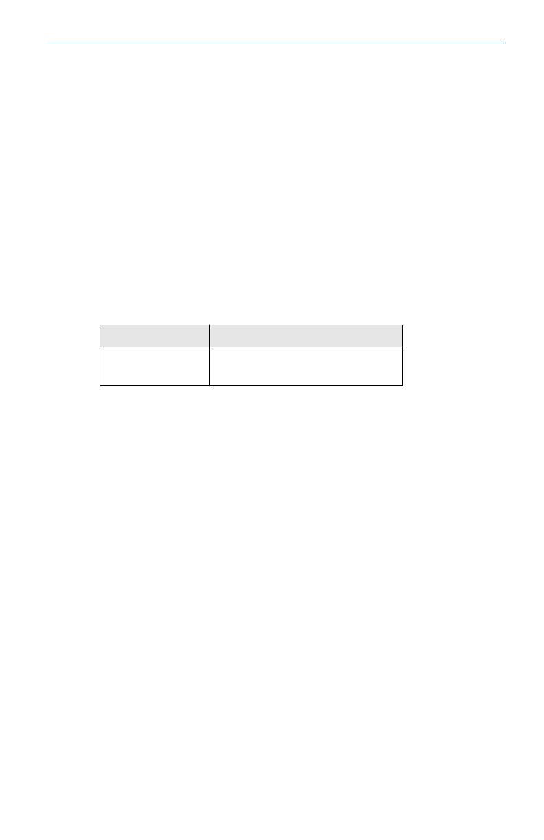
Altitude Pollution degree
5000 m max 4 (metallic enclosure)
2 (non-metallic enclosure)
3.3  Installing Equipment in North America
The US National Electrical Code® (NEC) and the Canadian Electrical
Code (CEC) permit the use of Division marked equipment in Zones
and Zone marked equipment in Divisions. The markings must be
suitable for the area classification, gas, and temperature class. This
information is clearly defined in the respective codes.
3.4  USA
I5 Intrinsic Safety; Nonincendive
Certificate 1053834
Standards FM 3600: 2022, FM 3610: 2018, FM 3611: 2021,
ANSI/UL 61010-1-2019 Third Edition ANSI/UL 60079-0:
2017, ANSI/UL 60079-11: 2013, ANSI-ISA-12.27.01–2022,
ANSI/UL 50E (1st Ed.)
Markings IS CL I, DIV 1, GP A, B, C, D when connected per
Rosemount drawing 03031-1024, CL I ZONE 0 AEx ia IIC
T4; NI CL 1, DIV 2, GP A, B, C, D; T4 (20 °C Ta +70 °C)
[HART®]; Type 4x
October2023 Quick Start Guide
Quick Start Guide 19
Specific Conditions for Use (X):
1. The Rosemount 3051HT transmitter housing may contain
aluminum and is considered a potential risk of ignition by
impact or friction. Care must be taken during installation and
use to prevent impact and friction.
2. The Rosemount 3051HT with the transient terminal block
(option code T1) will not pass the 500 VRMS dielectric strength
test; this must be considered during installation.
3. Equipment evaluated for atmospheric pressure range between
80 kPa (0,8 bar) to 110 kPa (1,1 bar).
4. Maximum process temperature limits shall be in accordance
with 03031-1053.
3.5  Canada
Intrinsic Safety
Certificate 1053834
Standards C22.2 No. 61010-1-12, C22.2 No. 25-17, C22.2 No. 94.2-20
Third Edition,
CSA Std C22.2 No. 213-17 + UPD 1 (2018) + UPD 2 (2019)
+ UPD 3 (2021), CAN/CSA-60079-0:19,
CAN/CSA-60079-11:14, ANSI-ISA-12.27.01 -2022, ANSI/UL
50E (1st Ed.)
Markings IS CL I GP ABCD T4
Ex ia IIC T4 Ga
(-20 °C Ta +70 °C);
Single seal - temp limits per 03031-1053, Type 4X, IP 68
Install per 03031-1024
Specific Conditions for Use:
1. The Rosemount 3051HT Transmitter housing may contain
aluminum and is considered a potential risk of ignition by
impact or friction. Care must be taken during installation and
use to prevent impact and friction.
2. The Rosemount 3051HT Transmitter with the transient
terminal block (Option code T1) will not pass the 500 VRMS
dielectric strength test; this must be considered during
installation.
3. Equipment evaluated for atmospheric pressure range between
80 kPa (0,8 bar) to 110 kPa (1,1 bar).
Quick Start Guide October2023
20 Emerson.com/Rosemount
  • Page 1 1
  • Page 2 2
  • Page 3 3
  • Page 4 4
  • Page 5 5
  • Page 6 6
  • Page 7 7
  • Page 8 8
  • Page 9 9
  • Page 10 10
  • Page 11 11
  • Page 12 12
  • Page 13 13
  • Page 14 14
  • Page 15 15
  • Page 16 16
  • Page 17 17
  • Page 18 18
  • Page 19 19
  • Page 20 20
  • Page 21 21
  • Page 22 22
  • Page 23 23
  • Page 24 24
  • Page 25 25
  • Page 26 26
  • Page 27 27
  • Page 28 28

Rosemount 3051HT Hygienic Pressure Transmitter Quick start guide

Type
Quick start guide

Ask a question and I''ll find the answer in the document

Finding information in a document is now easier with AI