Page is loading ...

1
36-5000 T2 Series Quick Assembly Guide
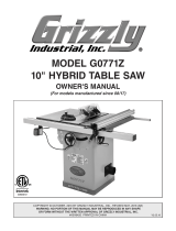
PACKAGE CONTENTS 36-5000 T2 AND 36-5100 T2
PC1
PC2 PC3
PC17
PC4
PC5
PC6
PC7
PC8
PC9
PC10
PC11
PC12
PC13
PC14
PC16
PC18
PC19
PC15
Saw Body
Left Leg
Right Leg
Rip Fence
Blade Guard
Miter Gauge
Push Stick
Throat Plate
Blade Wrench
36-5000 T2 - Steel Extension Wings (3)
36-5100 T2 - Cast Iron Extension Wings (2),
Steel Extension Wings (1)
Anti-Kickback Pawls
Adjustable Feet (2)
Fixed Wheels (2)
Hand Wheel Handles (2)
Rip Fence Handle
10 inch Blade
(Pre-Installed)
Rear Fence Rail
Front Fence Rail
Fence Guide
PC1
PC2
PC3
PC17
PC4
PC5
PC6
PC7
PC8
PC9
PC10
PC11
PC12
PC13
PC14
PC16
PC18
PC19
PC15

2
HARDWARE PACKAGE 36-5000 T2 AND 36-5100 T2
HP1
HP2
HP6
HP2 HP3
HP4 HP5
HP7
HP7
Hardware Bag “A” Hardware Bag “B” Hardware Bag “D”
Hardware Bag “F”
Hardware Bag “C”
006134 007188
006111
006111
005679
007187
007187
005733
005733 003059
006122
HP15
HP14
HP14
003578
HP1
HP3
HP2 HP2
HP4
HP5
Hardware Bag “A”
M8 x 75mm Carriage Bolt
M8 Nylock Nut
M8 Flat Washer
M6 x 72mm Carriage Bolt (4)
M6 Nylock Nut (4)
Hardware Bag “B”
M8 x 53mm Carriage Bolt (2)
M8 Nylock Nut (2)
Hardware Bag “C”
5/16-18 x 7/8 Hex Screw
w/Split Lock Washer (9)
5/16-18 Hex Flange Nut (3)
5/16-18 Set Screw (4)
(Only in 36-5100 T2)
Hardware Bag “D”
5/16-18 x 1 1/8 inch Flat
Countersunk Hex Screw (6)
5/16-18 Hex Flange Nut (10)
5/16-18 x 7/8 Hex Screw
w/Split Lock Washer (6)
Hardware Bag "F"
Rail Alignment Gauge
4mm T-Handle Allen Wrench
6mm Allen Wrench
3/16 inch Two-Way Allen Wrench L
Shape
5/32 L-Shaped Hex Wrench
(Only in 36-5100 T2)
HP20
HP21
HP22
HP23
HP6
HP14
HP14
HP15
HP7
HP7
HP7
Hardware Bag “E ”
Hardware Bag “G”
007188
006111
006110
006054
007187
HP18 HP19
HP15
HP14
Hardware Bag “E”
1/4-20 x 1/2 inch Button
Head Hex Screw w/ Split Lock
Washer (4)
1/4-20 x 1/2 inch Hex Screw
w/ Split Lock Washer (2)
HP18
HP19 HP14
HP15
HP7
Hardware Bag “G”
5/16-18 x 7/8 Hex Screw
w/Split Lock Washer (2)
5/16-18 Hex Flange Nut (4)
5/16-18 x 1 1/8 inch Flat Countersunk
Hex Screw (2)
007191
HP24
HP24
HP25
007080007083 007082 007081
HP20 HP21 HP22 HP23
007193
HP25

3
PACKAGE CONTENTS 36-5052 T2 AND 36-5152 T2
PC1
PC2 PC3
PC4
PC5
PC6
PC7
PC8
PC9
PC11
PC12
PC13
PC14 PC15
PC20 PC21 PC22
PC17 PC18 PC19
PC16
PC10
Saw Body
Left Leg
Right Leg
Rip Fence
Blade Guard
Miter Gauge
Push Stick
Throat Plate
Blade Wrench
36-5052 T2 - Steel Extension Wings (2)
36-5152 T2 - Cast Iron Extension Wings (2)
Anti-Kickback Pawls
Adjustable Feet (2)
Fixed Wheels (2)
Hand Wheel Handles (2)
Rip Fence Handle
10 inch Blade (Pre-Installed)
Rear Fence Rail
Front Fence Rail
Fence Guide
Wood Table Extension
Table Legs (2)
Wing Attachment Rail
PC1
PC2
PC3
PC17
PC4
PC5
PC6
PC7
PC8
PC9
PC10
PC11
PC12
PC13
PC14
PC16
PC18
PC19
PC15
PC20
PC21
PC22

4
HARDWARE PACKAGE 36-5052 T2 AND 36-5152 T2
HP1 HP2 HP3
HP4 HP5
Hardware Bag “A”
005679
006054 006110
HP7
Hardware Bag “C”
007187
HP2
HP6
Hardware Bag “B”
006134
005733
005733 003059
006122
Hardware Bag “F”
003578
HP1
HP3
HP2
HP16
HP2
HP4
HP5
Hardware Bag “A”
M8 x 75mm Carriage Bolt
M8 Nylock Nut
M8 Flat Washer
M6 x 72mm Carriage Bolt (4)
M6 Nylock Nut (4)
Hardware Bag “B”
M8 x 53mm Carriage Bolt (2)
M8 Nylock Nut (2)
Hardware Bag “C”
5/16-18 x 7/8 Hex Screw
w/Split Lock Washer (6)
5/16-18 Set Screw (4)
(Only in the 36-5152 T2)
Hardware Bag “D”
5/16-18 x 1 1/8 inch Flat
Countersunk Hex Screw (6)
5/16-18 Hex Flange Nut (10)
5/16-18 x 7/8 Hex Screw
w/Split Lock Washer (6)
Hardware Bag “E”
10-32 x 34.5mm Round Head
Phillips Screw (4)
7/32 x 1/2 Flat Washer (4)
10-32 Hex Nut (4)
8-16 x 3/4 Round Head
Phillips Screw (8)
5/16-18 x 7/8 Hex Screw
w/Split Lock Washer (3)
Hardware Bag "F"
Rail Alignment Gauge
4mm T-Handle Allen Wrench
6mm Allen Wrench
3/16 inch Two-Way Allen Wrench L Shape
5/32 L-Shaped Hex Wrench
(Only in 36-5152 T2)
Hardware Bag "G"
1/4-20 x 1/2 inch Button Head Hex Screw w/
Split Lock Washer (6)
1/4-20 x 1/2 inch Hex Screw w/ Split Lock
Washer (2)
HP20
HP21
HP22
HP23
HP6
HP14
HP12
HP14
HP17
HP26
HP27
HP18
HP28
HP19
HP15 HP9
HP10
HP7
HP7
HP7
HP11
HP7
Hardware Bag “D”
007188 007187
HP15
Hardware Bag “E ”
006111
007187
HP14
HP26 HP27 HP28
HP7
HP12
HP16
HP17
HP11
HP10
HP9
8 x 16 x 1t Flat Washer (3)
5/16-18 Hex Flange Nut (3)
(Only in the 36-5052 T2)
1/4-20 x 1 1/2 Pan Head Hex
Socket Screw (6)
1/4-20 x 1-1/2 Hex Head Screw (6)
6.74 x 20.63 x 1.58 Flat Washers (12)
1/4-20 Hex Nut (12)
Hardware Bag “E”
Hardware Bag “G”
HP18 HP19
006265
006262
006263 006264
006266
003059
006268
006267
007196
HP25
HP24
007191
HP24
007080007083 007082 007081
HP20 HP21 HP22 HP23
007193
HP25
006111
HP14

5
Avoid contact with blade teeth. KEEP blade
stored or lowered when possible.
• DO NOT lift saw without help. Hold it close to your body while
lifting. KEEP knees bent and lift with your legs, not your back.
• Fully assemble saw with leg assembly prior to use. Leg
assembly is an integral and necessary part of the support
structure for this saw.
• DO NOT modify saw, or create accessories not recommended
for use with this saw.
• Make sure power switch is in “OFF” position before connecting
to power supply.
• DO NOT connect to power supply until assembly is complete
TOOLS REQUIRED FOR ASSEMBLY (not included)
Step 1: STAND
Hardware Bag “A”
Figure 1
Figure 2
Figure 3
Figure 4
PC3 HP1
HP3
HP2
HP2
PC2
A
PC13
HP6
PC12
HP22
• Flat head screwdriver
• Phillips head screwdriver
• 8mm wrench
• 10mm wrench
• 12mm wrench
• 13mm wrench
• 3/8 inch wrench
• 7/16 inch wrench
• Framing (Carpenter’s)
Square
• Combination Square
• Straight Edge
1. Connect the two Tube Legs together by inserting the end
of the Left Leg PC2 into the end of the Right Leg PC3 .
Using a 13mm Wrench, secure them together with a M8 x
75mm Carriage Bolt HP1 , M8 Flat Washer H P3 , M8 Nylock
Nut HP2 and tighten. See Figure 1.
2. Insert the four open ends of the Tube Legs into the Leg
Collars A as shown. Using a 10mm Wrench, secure each
Leg to the Saw Body with (4) M6 x 72mm Carriage Bolts
HP4 and (4) M6 Nylock Nuts HP5 and tighten. See Figure 2.
Step 2: FIXED WHEELS AND
STATIONARY FEET
Hardware Bag “B”
1. Using a 13mm Wrench, attach the two Fixed Wheels PC13
to the Left Leg using the (2) M8 x 53mm Carriage Bolts
HP6 and M8 Nylock Nuts HP2 . One for each wheel as
shown in Figure 3.
2. Screw the Adjustable Feet PC12 into the threaded inserts in
the Right Leg.
3. Carefully stand the box right side up and remove packaging
once the machine has been lifted from the ground. See
Figure 4.
The machine is heavy, two people may be
required to stand the machine up.
4. The two Adjustable Feet PC12 can be raised and lowered by
rotating them clockwise or counterclockwise. The Feet
may be adjusted to level the Saw and can be locked in
place with the pre-assembled Set Screws using the
provided 6mm Allen Wrench HP22 . See Figure 3.

6
Step 3: FRONT AND REAR RAILS
Hardware Bag “C, D”
1. Using the supplied 3/16 inch T-Handle Allen Wrench, attach
the Front Rail PC18 [1] to the table front with two 5/16-18 x
1 1/8 inch Flat Countersunk Hex Screw HP15 and two 5/16-
18 Hex Flange Nuts HP14 . See Figure 5.
2. Using the supplied 3/16 inch T-Handle Allen Wrench, attach
the Rear Rail PC17 [2] to the table back using two 5/16-18 x
7/8 inch Hex Screw with Split Lock Washer HP7 . See Figure
7.
NOTE: Use the two aligning holes which are spaced 16 inch apart
to align the front and rear rails to the table aligning holes which
are also spaced 16 inch apart.
3. Use supplied Rail Alignment Gauge HP20 to ensure the rail is
the proper distance from the top of the table at each side
of the cast iron table. See Figure 6. Figure 5
Figure 6
Figure 7
1
2
Front RailFront Rail
Rear Rail
FRONT
BACK
HP15
HP7
HP14
HP14
PC20

7
Step 4: EXTENSION WINGS
For Models with Three Extension Wings
Hardware Bag “C, D, G”
Figure 8
Figure 9
3
3
LEFT EXTENSION LEFT EXTENSION
WING WING
RIGHT EXTENSION RIGHT EXTENSION
WING WING
RULER RULER
PC10 PC10
1. Attach the left extension wing PC10 [3] to the front rail
using two 5/16-18 x 1-1/8 inch Flat Countersunk Hex
Screws HP15 and 5/16-18 Hex Flange Nuts HP14 .
2. Attach the left extension wing PC10 [3] to the rear rail using
two 5/16-18 x 7/8 Hex Screws w/ Split Lock Washers HP7
and 5/16-18 Hex Flange Nuts HP14 .
3. Attach the left side extension wing PC10 [3] to the front and
rear rails using four 5/16-18 x 1 1/8 inch Flat Countersunk
Hex Screw HP15 and 5/16-18 hex ange nuts HP14 .
4. Attach the left side extension wing PC10 [3] to the side of
the saw table using three 5/16-18 x 7/8 inch hex head
screws with Split Lock Washers HP7 . See Figure 10.
5. Lay the two remaining extension wings PC10 [3] upside
down on the saw table. Place the two wings adjacent to
each other, so the holes patterns match. Fasten the two
wings together using three 5/16-18 x 7/8 inch hex head
screws with Split Lock Washers HP7 and 5/16 18 hex ange
nuts HP14 .
6. Turn the two wings fastened together over and fasten
them to side of the saw table using three 5/16-18 x 7/8
inch hex head screws with Split Lock Washers HP7 . See
Figure 9.
7. Secure the 2 joined Extension Wings PC10 to the front rail
using four 5/16-18 x 1-1/8 inch Flat Countersunk Hex
Screws HP15 and 5/16-18 Hex Flange Nuts HP14 .
8. Secure the 2 joined Extension Wings PC10 to the rear rail
using four 5/16-18 x 7/8 Hex Screws w/ Split Lock Washers
HP7 and 5/16-18 Hex Flange Nuts HP14 .
NOTE: Use a ruler to make sure the top edges of the wings are
flush with the top of the tabletop. See Figure 8.
NOTE: There are four 5/16-18 Set Screws HP24 for the cast iron
extension wing for the 36-5100 T2. Two Set Screws for each cast
iron Extension Wing. The set screws are used to adjust the level.
See Figure 9.
HP7
HP14
HP15
HP7
HP24

8
Step 5: EXTENSION WINGS
Figure 10
Step 6: WOOD EXTENSION TABLE
For the 36-5052 T2 and 36-5152 T2
Hardware Bag “E”
1. Lay the Wood Table Extension PC20 upside down on oor or
bench.
2. Position table legs PC21 in corner as shown in Figure 11 the
vertical wall of the angle plate on the leg should be against
the end wood wall of the table.
3. Fasten the legs to the table board with eight 8-16 x 3/4
Round Head Phillips Screw HP12 .
4. Feed four 10-32 x 34.5mm Round Head Phillips Screw HP9
with four 7/32 x 1/2 Flat Washers HP10 and 10-32 Hex Nut
HP11 through the drilled holes from the outside, then
assemble the nuts onto the screws and tighten.
Figure 11
3
3
LEFT EXTENSION LEFT EXTENSION
WING WING
RIGHT EXTENSION RIGHT EXTENSION
WING WING
RULER
PC20
PC21
HP9
HP12
PC10
PC10
1. Attach both extension wings PC10 [3] to the front rail using
four 5/16-18 x 1-1/8 inch Flat Countersunk Hex Screws
HP15 and 5/16-18 Hex Flange Nuts HP14 .
2. Attach both extension wings PC10 [3] to the rear rail using
four 5/16-18 x 7/8 Hex Screws w/ Split Lock Washers HP7
and 5/16-18 Hex Flange Nuts HP14 .
3. Attach both right extension wings PC10 [3], to the Front and
Rear rails using four 5/16-18 x 1-1/8 inch Flat Countersunk
Hex Screw HP15 and 5/16-18 Hex Flange Nuts HP14 .
4. Attach the extension wings PC10 [3] to the table using three
5/16-18 x 7/8 inch Hex Head Screws with Split Lock
Washers HP7 for each wing. See Figure 10.
NOTE: Use a ruler to make sure the top edges of the wings are
flush with the top of the tabletop. See Figure 10.
NOTE: There are four 5/16-18 Set Screws HP24 for the cast iron
extension wings for the 36-5100 T2. Two Set Screws for each cast
iron Extension Wing. The set screws are used to adjust the level.
See Figure 9.
For the 36-5052 T2 and 36-5152 T2
Hardware Bag “D”

9
Figure 13
FENCE GUIDE
Figure 14
Figure 15
Figure 12
HP7
HP20
A
B
C
D
HP30
FENCE GUIDE AND POWER
CONTROL BOX
1. Attach the fence guide PC19 to the front rail using four (for
36-5000 T2 and 36-5100 T2) or six (for 36-5052 T2 and
36-5152 T2) 1/4-20 x 1/2 inch Button Head Hex Screw w/
Split Lock Washer HP18 through the holes C on the
bottom side of the front rail.
2. Align the two holes in the switch box bracket with the holes
underneath the front rail, shown in Figure 15, located on
the left side of the saw. Secure the switch box F3 to the
front rail using two 1/4-20 x 1/2 inch Hex Screw w/ Split
Lock Washer HP19 .
5. Loosely assemble three 5/16-18 x 7/8 inch Hex Head
Screws with Split Lock Washers HP7 , 8 x 16 x 1t Flat
Washers HP16 and three 5/16-18 Hex Flange Nuts HP14 into
the three holes into the side of the extension wing as
shown. See Figure 12.
NOTE: The 5/16-18 Hex Flange Nuts HP14 are only used on the 36-
5052 T2.
6. Carefully lower the slotted wing attachment PC22 down onto
the screws on the extension wing. Tighten the screws after
the wood table is leveled with the extension wing.
7. Using the Rail Alignment Gauge HP20 adjust the feet B in
the table legs so the top of the table is at the proper
distance from the rail.
8. Drill 1/4 inch holes through the rail holes A into the
wood table on the front and back rails. See Figure 13.
9. Fasten Wood Table Extension to Front Rail using six 1/4-20
x 1-1/2 Pan Head Hex Socket Screws HP17 , 6.74 x 20.63 x
1.58 Flat Washers HP27 and 1/4-20 Hex Nuts HP28 .
10. Fasten Wood Table Extension to Rear Rail using six 1/4-20
x 1-1/2 Hex Head Screws HP26 , 6.74 x 20.63 x 1.58 Flat
Washers HP27 and 1/4-20 Hex Nuts HP28 .
Hardware Bag “E” for 36-5000T2 and 36-5100T2
Hardware Bag “G” for 36-5052T2 and 36-5152 T2

10
Step 10: THROAT PLATE
Step 8: INSTALLING THE HANDLES
Elevation and Bevel Hand Wheels
The Rip Fence Handle is packaged individually and labeled
accordingly, please install as follows:
1. Screw the Labeled Handle PC15 to the Rip Fence with the
supplied Hex Wrench. See in Figure 18.
Step 9: INSTALLING THE RIP
FENCE HANDLE
NOTE: Refer to Operator's Manual for storage locations - Wrenches,
Blade Guard, Anti-kick back pawls, and Push-stick.
NOTE: Refer to Operator's Manual page 23 for throat plate
instillation instructions.
IMPORTANT: Before raising Blade you must release Bevel Lock
and tilt Blade 45° and remove styrofoam block under Motor
Housing. See Figure 19.
To reduce the risk of serious personal
injury, the Riving Knife MUST be installed and properly
positioned for every possible through and non-through cut.
1. Your Saw is shipped with the Blade and Riving Knife
installed and properly aligned. The Riving Knife comes
installed in the low, non-through cutting position. Prior to
operating your Saw, check to make sure the alignment
of the Blade to the Miter Slot and the Riving Knife to the
Blade was not affected by shipping. To check alignment of
the Blade and Riving Knife, see page 27 in the Assembly
section of the Operator’s Manual.
2. The Riving Knife comes installed in the low, non-through
cutting position. To attach the Anti-Kickback Pawls and
Blade Guard Assemblies, the Riving Knife MUST be in
the raised position as shown in Figure 38, page 32 of the
Operator’s Manual. To raise and lower the Riving Knife, see
Riving Knife Height Settings on page 32.
3. When installing Riving Knife, Anti-Kickback Pawls and Blade
Guard, Blade MUST be at 90° setting and raised to the
maximum height. See “RAISING AND LOWERING BLADE”
section on page 30 of the Operator’s Manual.
Step 11: BLADE AND RIVING KNIFE
The elevation and Bevel Handles are packaged together in the box,
please install as follows:
1. Insert one Handle PC14 to the Elevation Hand Wheel located
in the front of the Saw, as seen in Figure 17.
2. Insert one Handle PC14 to the Bevel Hand Wheel located on
the right side of the Saw, as seen in Figure 18.
Figure 17
Figure 18
PC14
PC14
PC15
Figure 19
(REMOVE)(REMOVE)

11
Step 13: BLADE GUARD
If the metal portion of the Blade Guard
Assembly is not parallel to the table, the Riving Knife is not
in the raised position. Remove Blade Guard Assembly and
Anti-Kickback Pawls and raise Riving Knife, then reinstall
the Anti-Kickback Pawls and the Blade Guard Assembly.
NOTE: Also reference Figure 37, page 32 of the Operator’s Manual.
To Remove the Blade Guard Assembly:
1. Lift the Blade Guard Assembly Lock Lever D to the
unlocked position.
2. Rotate the Guard back and slide the Pin B from the
Riving Knife Slot.
NOTE: Check the Blade Guard for clearances and free movement.
Step 12: ANTI-KICKBACK PAWLS
To reduce the risk of serious personal
injury, Anti-Kickback Pawls MUST be in place when making
a through cut.
Figure 23
Figure 22
PC5
A
PC11
A
B
B
C
D
1. See Figure 22 and locate the Anti-Kickback Pawls Mounting
Slot A in the middle of the top edge of the Riving Knife.
2. Slide Slot in the middle of the Anti-Kickback Pawls
Assembly PC11 along the top of the Riving Knife until the
stem B locates the center slot A on the Riving Knife.
3. Depress the stem on the Anti-Kickback Pawls Assembly to
allow the Assembly to drop into the slot. Push down on
the Anti-Kickback Pawls Assembly until it snaps into place
and locks. Release stem. NOTE: Pull up on the Anti-
Kickback Pawls to make sure it is locked in place.
To remove the Anti-Kickback Pawls, depress the stem B and pull
the Anti-Kickback Assembly off the Riving Knife.
To reduce the risk of serious personal
injury, the Blade Guard MUST be in place when making a
through cut.
1. Before installing the Blade Guard Assembly PC5 , make sure
the riving knife is raised to the through-cut position.
2. While holding the Blade Guard Assembly in a vertical
position, hook the Locating Pin B at the back end of the
Blade Guard Assembly into the slot at the back edge of the
Riving Knife.
3. Rotate the Blade Guard Assembly toward the front of the
Saw until the metal portion C of the Blade Guard
Assembly is parallel to the Table as shown in Figure 23.
4. While holding down on the front of the metal portion of the
Guard C press the Blade Guard Lock Lever D down
until it snaps into the locked position. Check to make sure
the Guard is locked onto the Riving Knife by pulling on the
Guard. If the Guard is not locked, the Blade Guard Lock
Lever will ip up to the unlocked position.
/