OM-EE
13
g. As part of the daily cleaning program,
clean soiled external and internal
surfaces. Remember to check the sides
of the unit and control housing.
h. To remove stuck materials, use a brush,
sponge, cloth, plastic or rubber scraper,
or plastic wool with the cleaning solution.
To reduce effort required in washing, let
the detergent solution sit in the kettle
and soak into the residue. Do NOT use
abrasive materials or metal tools that
might scratch the surface. Scratches
make the surface harder to clean and
provide places for bacteria to grow.
Do NOT use steel wool, which may
leave particles in the surface and cause
eventual corrosion and pitting.
i. The outside of the unit may be polished
with a stainless steel cleaner such as
“Zepper” from Zep Manufacturing Co. Or
Groen Degreaser. (Part Number
140830)
j. When equipment needs to be sanitized,
use a solution equivalent to one that
supplies 200 parts per million available
chlorine. Obtain advice on sanitizing
agents from your supplier of sanitizing
products. Following the supplier’s
instructions, apply the agent after the
unit has been cleaned and drained.
Rinse off the sanitizer thoroughly.
CAUTION
NEVER LEAVE A CHLORINE SANITIZER
IN CONTACT WITH STAINLESS STEEL
SURFACES LONGER THAN 30 MINUTES.
LONGER CONTACT CAN CAUSE
STAINING AND CORROSION.
k. It is recommended that each piece of
equipment be sanitized just before use.
l. If there is difficulty removing mineral
deposits or a film left by hard water or
food residues, clean the kettle
thoroughly and then use a deliming
agent, like Groen Delimer/Descaler (Part
Number 140513) or Lime-A-Way® from
Ecolab, in accordance with the
manufacturer’s directions. Rinse and
drain the unit before further use.
m. If cleaning problems persist, contact
your cleaning product representative for
assistance.
Troubleshooting
Your Groen kettle is designed to operate smoothly and efficiently if properly maintained. However, the
following is a list of checks to make in the event of a problem. Wiring diagrams are furnished inside the
service panel and in this manual. If an item on the list is followed by
<
<<
<, the work should be done by
a qualified service representative.
USE OF ANY REPLACEMENT PARTS OTHER THAN THOSE SUPPLIED BY GROEN OR THEIR
AUTHORIZED DISTRIBUTORS CAN CAUSE INJURY TO THE OPERATOR AND DAMAGE TO THE
EQUIPMENT AND WILL VOID ALL WARRANTIES.
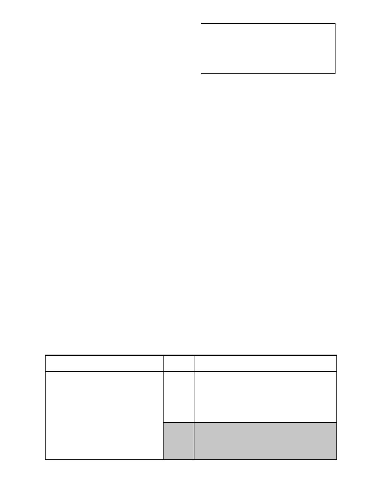
SYMPTOM WHO WHAT TO CHECK
<
<<
<indicates items which must be performed by an authorized technician.
Kettle will not heat, and heating indicator
will not come on.
User a. Electric power supply to the unit.
b. Water level in jacket.
c. Control circuit fuses in the control console.
REPLACE BLOWN FUSES ONLY WITH A
FUSE OF THE SAME AMP RATING. a
HIGHER RATED FUSE WILL NOT PROTECT
THE UNIT OR THE BUILDING.
Auth
Service
Rep Only
d. For loose or broken wires.
<
f. Operation of variable thermostat. <
g. Low water cutout switch. <
h. Water probe.<
i. That high limit pressure switch is closed. <


