Noritz GQ-C2859WX-FF US NG Operating instructions
- Category
- Water heaters & boilers
- Type
- Operating instructions
This manual is also suitable for

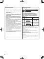
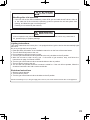
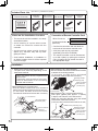
Potential dangers from accidents during installation and use are divided into the following three
categories. Closely observe these warnings, they are critical to your safety.
Prohibited
Disconnect
Power
Ground
Be sure to do
WARNING:
If the information in this manual is not followed exactly, a re or explosion may result
causing property damage, personal injury or death.
NORITZ AMERICA
CORPORATION
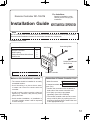
Installation Manual
CONDENSING TANKLESS GAS WATER HEATER
EZ111DV (GQ-C3259WX-FF US)
EZ98DV (GQ-C2859WX-FF US)
DANGER indicates an imminently hazardous situation which,
if not avoided, will result in death or serious injury.
WARNING indicates a potentially hazardous situation which,
if not avoided, could result in death or serious injury.
CAUTION indicates a potentially hazardous situation which,
if not avoided, may result in minor or moderate injury.
DANGER
WARNING
CAUTION
SBB80TB
Rev. 01/17
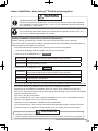
Requests to Installers
• In order to use the water heater safely, read this installation manual carefully, and follow the
installation instructions.
• Failures and damage caused by erroneous work or work not as instructed in this manual are not
covered by the warranty.
•
Check that the installation was done properly in accordance with this Installation Manual upon completion.
•
After completing installation, please either place this Installation Manual in a plastic pouch and
attach it to the side of the water heater (or the inside of the pipe cover or recess box if applicable),
or hand it to the customer to retain for future reference. Also, be sure to ll in all of the required
items on the warranty and to hand the warranty to the customer along with the Owner's Guide.
CAUTION
FOR USE IN RESIDENTIAL OR MANUFACTURED HOME APPLICATIONS.
Installation must conform with local codes, or in the absence of
local codes, the National Fuel Gas Code, ANSI Z223.1/NFPA 54-
latest edition and/or the Natural Gas and Propane Installation
Code CSA B149.1 - latest edition.
When applicable, installation must conform with the Manufactured
Home Construction and Safety Standard, Title 24 CFR, Part
3280 or the Canadian Standard CAN/CSA-Z240 MH Mobile
Homes, Series M86.
Noritz America reserves the right to discontinue, or change at any
time, the designs and/or specications of its products without notice.
CERTIFIED
R
Low NOx Approved by SCAQMD
14 ng/J or 20 ppm
(Natural Gas Only)

2
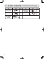
1.
Included Accessories
The following accessories are included with the unit.
Check for any missing items before starting installation.
Q’ty
ShapePart
Anchoring Screw
1
each
Part Shape
Q’ty
7
Remote Controller
(See p. 44)
Remote Controller
Cord (6ft (2m))
Wall Mounting
Bracket
1
Owner's Guide, Warranty,
Installation Manual
(this document)
1
1

3
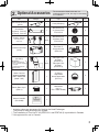
2.
Optional Accessories
The accessories listed below are not
included with the units, but may be necessary
for installation.
Q’ty
ShapePartPart Shape
Q’ty
Remote Controller
Cord (26ft (8m))
Quick Connect Cord
(QC-2)
1
1
1
each
Isolation Valves*
(includes pressure
relief valve)
Bird Screen for
2"(50mm) PVC
VT2-PVCS
Bird Screen for
3" (75mm) PVC
VT3-PVCS
2
2
PVC Concentric
Termination
2"(50mm) : PVC-2CT
3"(75mm) : PVC-3CT
1
Note: Additional vent pieces are available; consult the latest product catalogue for details.
3"(75mm)
Horitzontal
Hood Termination
(PVT-HL)
2
1
each
1 1
Noritz Connect
Wireless Adapter
NWC-ADAPTER
(NAW-1 US)
Outdoor Vent Cap
(VC-6)
2" SV Conversion Kit
(SV-CK-2)
Flex Vent 2"
Conversion Kit
(EZ2-CK)
• 90 Elbow
(With Inlet Screen)
•
2"×3" Increaser coupling
• 2" Pipe
• Installation Manual
(Check List)
11
1
Neutralizer
(NC-1)
(For 1 water heater)
Plastic Rain Cap***
(PRC-1)
* Isolation valves are necessary for ushing the Heat Exchanger.
They allow for easy ushing of the system.
** The installation of Flex Vent 2" Kit (EZ2FVK-1 and EZ2FVK-2) is prohibited in Canada.
*** Not approved for use in Canada.
1
Flex Vent 2" Kit
25 Feet**
(EZ2FVK-1)
Flex Vent 2" Kit
35 Feet**
(EZ2FVK-2)
Remote Controller
(RC-9018M)
1

4
Isolation Valve*
Exhaust
Intake
Cold Water
Hot Water
Quick Connect Cord
Union
Gas Valve
Pressure
Relief Valve
To drain outlet
To drain outlet
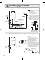
Make this distance
as short
as possible.
The hot water
temperature will
become unstable as
the pipe length
increases.
Size the piping to allow for the
maximum flow rates of the units.
* Isolation valves are necessary
for flushing the Heat Exchanger.
They allow for easy flushing
of the system.
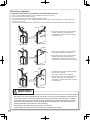
Distance on sides
3 - 18 in. (75 - 457 mm)
Leave enough clearance around
the plumbing to apply insulation.
It will be necessary to add bends
to the piping to ensure that this
clearance is available.
The backflow preventer should be placed
upstream of the cold water branch.
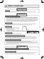
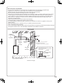
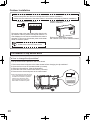
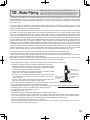
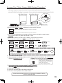
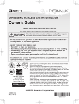
3.
Quick Connect Multi System Installation
• The Quick Connect Multi System allows the installation of two units together utilizing only the Quick
Connect Cord.
Typical Plumbing
* When connecting two units, use only a
single remote controller.
Note: Connect the remote
controller to only one
of the units.
Units must be same
model in order to
quick connect.
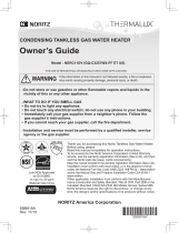
System Diagram
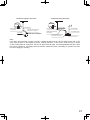
• Insulate the hot water piping to prevent heat loss. Insulate and apply heating materials to the
cold water supply piping to prevent heat loss and freezing of pipes when exposed to excessively
cold temperatures.
The Quick Connect Cord is 6 ft.(2m) long. Install the units 3-18" (75-457mm) apart from each
other to ensure the cord will be able to reach between the units. (See Typical Plumbing diagram).
(If the distance between the two units is too great, not only will the cord not be able to reach,
but the water temperature may also become unstable because of the difference in pipe length
between the two units).
G
Quick Connect
Cord
Remote Controller Cord
Gas Supply Piping
Cold Water Supply
Hot Water Supply
Remote Controller
Terminal Block
Cord
Connector
Cord
Connector

5
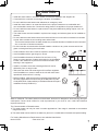
4.
Before Installation
Checkup
• Check the xing brackets and vent pipe yearly for damage or wear. Replace if necessary.
DANGER
Do Not Use Equipment for Purposes Other Than Those Specied
•
Do not use for other than increasing the temperature of the water supply, as unexpected accidents may occur as a result.
Check Water Supply Quality
• If the water supply is in excess of 12 grains per gallon (200 mg/L) of hardness, acidic or otherwise
impure, treat the water with approved methods in order to ensure full warranty coverage.
WARNING
CAUTION
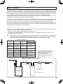
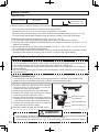
Check the Gas
• Check that the rating plate indicates the
correct type of gas.
• Check that the gas supply line is sized for
199,900 or 180,000 Btuh.
199,900 Btuh : EZ111DV(GQ-C3259WX-FF US)
180,000 Btuh : EZ98DV(GQ-C2859WX-FF US)
Check the Power
• The power supply required is 120VAC, at 60Hz.
Using the incorrect voltage may result in re or electric shock.
Use Extreme Caution if Using With a Solar Pre-Heater
• Using this unit with a solar pre-heater can lead to unpredictable output temperatures and
possibly scalding. If absolutely necessary, use mixing valves to ensure output temperatures do
not get to scalding levels. Do not use a solar pre-heater with the quick-connect multi-system.
Precautions for Mobile Home Installation
• Verify that the gas supply type matches the gas type listed on the rating plate. If a gas conversion
must be done, follow the instructions listed in the gas conversion kit manual.
• If this product will be installed indoors, usage of the SV conversion kit (SV-CK-2) and Flex
Vent 2" Conversion Kit (EZ2-CK) are prohibited. Make sure to follow all clearance and venting
requirements outlined in this manual.
Precautions on Vent Pipe Replacement
•
The vent system will almost certainly need to be replaced when this appliance is being installed. Only
use vent materials that are specied in this Installation Manual for use on this appliance. Refer to the
"Venting the Water Heater" section for details. If PVC, CPVC, or Category IV listed pipe is already installed,
check for punctures, cracks, or blockages and consult with the vent pipe manufacturer before reusing.
If the exible polypropylene pipe is already installed, replace to the new exible polypropylene pipe.
Improper venting may result in res, property damage or exposure to Carbon Monoxide.
Snow Precaution
• If this product will be installed in an area where snow is known to accumulate, protect the vent
termination from blockage by snow drifts or damage from snow falling off of roofs.
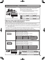
: Max.
:
: AC 120Volts 60Hz, less than amperes
Btu/hBtu/h - Min.
Gal/h(
: Min. psipsi - Max.
: "W.C.
l/h)
: Min. "W.C."W.C.- Max.
-For Indoor, Outdoor or Manufactured Home(Mobile Home) Installation.
(Pour installation dans une maison préfabriquée(Mobile)).
Model(Modèle) :
Type of Gas(Type de gaz)
Input Rating(Debit calorifique)
Recovery Rating
(Calibre de recouvrement)
Inlet Gas Pressure
(Pression de gaz entrée)
Manifold Pressure
(Pression d’admission)
Water Supply Pressure(Pression d’eau)
Electrical Rating
(Régime nominal électrique)
-For gas conversion information, contact Noritz America.
(Pour I’ information de conversion de gaz, contact Noritz America.)
-Direct Vent Automatic Instantaneous Water Heater (“Category IV”).
(Chauffe-eau instantané automatique à évent direct( “Catégorie IV”).)
-Installations above 2000 ft(610m) require an adjustment. See Installation Instructions for
details.(Installations au-dessus de 2000 ft(610m) exigent un ajustement. Voir les
instructions d’installation pour des détails.)
NORITZ AMERICA CORPORATION
11160 Grace Avenue, Fountain Valley, CA 92708
Tel(Tél ): (866)766-7489
Made in Japan(Fabriqu
é
au JAPON)
: Natural Gas(Gaz Naturel)
Low NOx approved by SCAQMD(<14ng/J or 20ppm)
ANSI Z21.10.3 CSA 4.3-2015
18,000199,900
237
897
15015
0
3.5 10.5
4
EZ111DV(GQ-C3259WX-FF US)
e.g. EZ111DV(GQ-C3259WX-FF US)

6
5.
Choosing Installation Site
• Locate the vent terminal so that there are no obstacles around the termination and so that exhaust
can't accumulate. Do not enclose the termination with corrugated metal or other materials.
• Avoid places where res are common, such as those where gasoline,
benzene and adhesives are handled, or places in which corrosive gases
(ammonia, chlorine, sulfur, ethylene compounds, acids) are present.
Using the incorrect voltage may result in re or cracking.
• Avoid installation in places where dust or debris will accumulate.
Dust may accumulate and reduce the performance of the unit's fan.
This can result in incomplete combustion.
• Avoid installation in places where special chemical agents
(e.g., hair spray or spray detergent) are used.
Ignition failures and malfunction may occur as a result.
• Carbon Monoxide Poisoning Hazard. Do not install this water heater in a
recreational vehicle or on a boat.
• The manufacturer does not recommend installing the water heater in an
attic due to safety issues.
If you install the water heater in an attic:
•
Make sure the unit will have enough combustion air and proper ventilation.
• Keep the area around the water heater clean. Dust may accumulate
and reduce the performance of the unit's fan. This can result in incomplete
combustion.
• Place the unit for easy access for service and maintenance.
• A drain pan, or other means of protection against water damage, is
required to be installed under the water heater in case of leaks.
DANGER
WARNING
Prohibited
* Locate the appliance in an area where leakage from the unit or connections will not result in damage
to the area adjacent to the appliance or to the lower oors of the structure. When such installation
locations cannot be avoided, a suitable drain pan, adequately drained, must be installed under the
appliance. The pan must not restrict combustion air ow.
* As with any water heating appliance, the potential for leakage at some time in the life of the product
does exist. The manufacturer will not be responsible for any water damage that may occur.

7
• Avoid installation above gas ranges or stoves.
• Avoid installation between the kitchen fan and stove. If oily
fumes or a large amount of steam are present in the installation
location, take measures to prevent the fumes and steam from
entering in the equipment.
• Install in a location where the exhaust gas ow will not be
affected by fans or range hoods.
• Take care that noise and exhaust gas will not affect neighbors.
Avoid installation on common walls as the unit will make some
operational noises while it is running.
• Before installing, make sure that the exhaust ue termination will
have the proper clearances according to the National Fuel Gas
Code (ANSI Z223.1-latest edition) or the Natural Gas and Propane
Installation Code (CSA B149.1).
State of California: The water heater must be braced, anchored or strapped to avoid moving during an
earthquake. Contact local utilities for code requirements in your area or call: 1-866-766-7489 and
request instructions.
Be sure to do
Prohibited
Prohibited
CAUTION
The Commonwealth of Massachusetts:
1) This water heater can only be used in outdoor applications if the usage is restricted to summertime
usage exclusively.
2) The water heater can be used for hot water only and not in a combination of domestic and space heating.
For Venting Manufacturers Requirements, see websites listed below:
Noritz N-Vent www.noritz.com
• Install the water heater in a location where it is free from obstacles and stagnant air.
• Consult with the customer concerning the location of installation.
• Do not install the water heater near staircases or emergency exits.
• Install the water heater in an area that allows for the proper clearances to combustible and
non-combustible construction. Consult the rating plate on the appliance for proper clearances.
• Do not install the water heater in a place where it may be threatened by falling objects, such as
under shelves.
• The water heater must be installed in a place where supply and exhaust pipes can be installed as
directed.
• Do not install the water heater where the exhaust will blow on outer walls or material not resistant
to heat. Also consider the surrounding trees and animals.
The heat and moisture from the water heater may cause discoloration of walls and resinous materi-
als, or corrosion of aluminum materials.
• Do not locate the vent termination directed towards a window or any other structure which has
glass or wired glass facing the termination.
•
Avoid installation where the unit will be exposed to excessive winds.

8
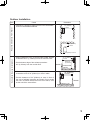
6.
Installation Clearances
Before installing, check for the following:
Indoor Installation
Install in accordance with relevant building and mechanical codes, as well as any local, state or
national regulations, or in the absence of local and state codes, to the National Fuel Gas Code
ANSI Z223.1/NFPA 54 – latest edition. In Canada, see the Natural Gas and Propane Installation
Code CSA B149.1 - latest edition for detailed requirements.
WARNING
Item
Distance from combustibles
• Maintain the following clearances
from both combustible and
non-combustible materials.
Check Illustration
In order to facilitate inspection and repair it
is recommended to leave:
•
8" (200mm) or more on either side of the unit.
•
24" (600mm) or more in front of the unit.
• 3" (75mm) or more above and below the
vent pipe.
Securing of space for
repair/inspection
24" (600mm)
or more
Distance from
the side
12" (300mm)
or more
3" (75mm)
or more
4" (100mm)
or more
3" (75mm) or more
3" (75mm) or more
8" (200mm)
or more
8" (200mm)
or more
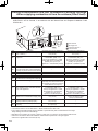
<When the indoor air supply>
• If the unit will be installed in the vicinity of
a permanent kitchen range or stove that
has the possibility of generating steam
that contains fats or oils, use a dividing
plate or other measure to ensure that the
unit is not exposed to air containing such
impurities.
* The dividing plate should be of
non-combustible material of a width
greater than the water heater.
Exhaust hood
Range
Dividing plate
Water
heater
Cooking Equipment

9
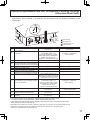
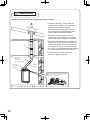
Outdoor Installation
Item Check
• When installing the unit on a balcony, etc., secure an
evacuation route of 24" (600mm) or more in width.
• Provide clearance of 24" (600mm) or more in front of
the unit to facilitate inspection and repair. Do not install
the unit in a location where the unit is out of reach, such
as the wall of the second oor.
• When installing the unit in a common side corridor, provide
a clearance of 47" (1,190mm) or more in front of the unit.
• Set the bottom edge of the exhaust port about
84" (2,130mm) from the corridor oor.
Handrail
common side
corridor
balcony, etc.
Handrail
about 84"
(2,130mm)
• Maintain the following clearance from both combustible
and non-combustible materials.
Surrounding the area of installation
24" (600mm)
or more
47" (1,190mm)
or more
Required Clearances From Heater
Illustration
24" (600mm)
or more
36" (900mm)
or more
3" (75mm) or more

10
DescriptionRef
A=
Clearance above grade, veranda, porch,
deck, or balcony
B=
Clearance to window or door that may
be opened
C=
Clearance to permanently closed window
D=
Vertical clearance to ventilated soffit located
above the terminal within a horizontal distance
of 2 feet (61 cm) from the center line of the terminal
*
E=
Clearance to unventilated soffit
*
F=
Clearance to outside corner
*
G=
Clearance to inside corner
*
H=
Clearance to each side of center line
extended above meter/regulator assembly
I=
Clearance to service regulator vent outlet
J=
Clearance to nonmechanical air supply
inlet to building or the combustion air inlet
to any other appliance
K=
Clearance to a mechanical air supply inlet
6 ft (1.83 m)
L=
Clearance above paved sidewalk or paved
driveway located on public property
Clearance under veranda, porch, deck,
or balcony
7 ft (2.13 m)†
M=
1
In accordance with the current CSA B149.1 Natural Gas and Propane Installation Code
2
In accordance with the current ANSI Z223.1 / NFPA 54 National Fuel Gas Code
†
A vent shall not terminate directly above a sidewalk or paved driveway that is located between two single
family dwellings and serves both dwellings.
‡ Permitted only if veranda, porch, deck, or balcony is fully open on a minimum of two sides beneath the floor
.
* Clearance in accordance with local installation codes and the requirements of the gas supplie
r.
Clearance to opposite wall is 24 inches (60 cm).
12 in (30 cm)‡
*
12 in (30 cm)
6 in (15 cm) for appliances
≤ 10,000 Btuh (3kW), 12 in
(30 cm) for appliances > 10,000
Btuh (3kW) and ≤ 100,000 Btuh
(30 kW), 36 in (91 cm) for
appliances > 100,000 Btuh (30 kW)
Above a regulator within 3 ft (91 cm)
horizontally of the vertical center line of
the regulator vent outlet to a maximum
vertical distance of 15 ft (4.5 m)
6 in (15 cm) for appliances
≤ 10,000 Btuh (3kW), 9 in
(23 cm) for appliances > 10,000
Btuh (3kW) and ≤ 50,000 Btuh
(15 kW), 12 in (30 cm) for
appliances > 50,000 Btuh (15 kW)
6 in (15 cm) for appliances
≤ 10,000 Btuh (3kW), 12 in
(30 cm) for appliances > 10,000
Btuh (3kW) and ≤ 100,000 Btuh
(30 kW), 36 in (91 cm) for
appliances > 100,000 Btuh (30 kW)
6 in (15 cm) for appliances
≤ 10,000 Btuh (3kW), 9 in
(23 cm) for appliances > 10,000
Btuh (3kW) and ≤ 50,000 Btuh
(15 kW), 12 in (30 cm) for
appliances > 50,000 Btuh (15 kW)
*
*
*
*
**
*
*
*
3 ft (91 cm) above if within
10 ft (3 m) horizontally
*
12 in (30 cm)
Vent Terminal
D
E
B
B
F
B
A
G
H
I
C
B
M
K
J
B
B
L
Air Supply Inlet
Area Where Terminal
is Not Permitted
A
I
US Direct Vent Installations
2
Canadian Direct Vent Installations
1
Clearance Requirements from Vent Terminations to Building Openings
<When supplying combustion air from the outdoors (Direct Vent)>
* All clearance requirements are in accordance with ANSI Z21.10.3 and the National Fuel Gas Code,
ANSI Z223.1 and in Canada, in accordance with the Natural Gas and Propane Installation Code
CSA B149.1.

11
DescriptionRef
A=
Clearance above grade, veranda, porch,
deck, or balcony
B=
Clearance to window or door that may
be opened
C=
Clearance to permanently closed window
D=
Vertical clearance to ventilated soffit located
above the terminal within a horizontal distance
of 2 feet (61 cm) from the center line of the terminal
*
E=
Clearance to unventilated soffit
*
F=
Clearance to outside corner
*
G=
Clearance to inside corner
*
H=
Clearance to each side of center line
extended above meter/regulator assembly
I=
Clearance to service regulator vent outlet
J=
Clearance to nonmechanical air supply
inlet to building or the combustion air inlet
to any other appliance
K=
Clearance to a mechanical air supply inlet
6 ft (1.83 m)
L=
Clearance above paved sidewalk or paved
driveway located on public property
Clearance under veranda, porch, deck,
or balcony
7 ft (2.13 m)†
M=
1
In accordance with the current CSA B149.1 Natural Gas and Propane Installation Code
2
In accordance with the current ANSI Z223.1 / NFPA 54 National Fuel Gas Code
†
A vent shall not terminate directly above a sidewalk or paved driveway that is located between two single
family dwellings and serves both dwellings.
‡ Permitted only if veranda, porch, deck, or balcony is fully open on a minimum of two sides beneath the floor
.
* Clearance in accordance with local installation codes and the requirements of the gas supplie
r.
Clearance to opposite wall is 24 inches (60 cm).
12 in (30 cm)‡
*
12 in (30 cm)
6 in (15 cm) for appliances
≤ 10,000 Btuh (3kW), 12 in
(30 cm) for appliances > 10,000
Btuh (3kW) and ≤ 100,000 Btuh
(30 kW), 36 in (91 cm) for
appliances > 100,000 Btuh (30 kW)
Above a regulator within 3 ft (91 cm)
horizontally of the vertical center line of
the regulator vent outlet to a maximum
vertical distance of 15 ft (4.5 m)
4 ft (1.2 m) below or to side
of opening; 1 ft (300 mm)
above opening
6 in (15 cm) for appliances
≤ 10,000 Btuh (3kW), 12 in
(30 cm) for appliances > 10,000
Btuh (3kW) and ≤ 100,000 Btuh
(30 kW), 36 in (91 cm) for
appliances > 100,000 Btuh (30 kW)
4 ft (1.2 m) below or to side
of opening; 1 ft (300 mm)
above opening
*
*
*
*
**
*
*
*
3 ft (91 cm) above if within
10 ft (3 m) horizontally
*
12 in (30 cm)
US Non-Direct Vent Installation
2
Canadian Non-Direct Vent Installation
1
Vent Terminal
Air Supply Inlet
Area Where Terminal
is Not Permitted
* All clearance requirements are in accordance with ANSI Z21.10.3 and the National Fuel Gas Code,
ANSI Z223.1 and in Canada, in accordance with the Natural Gas and Propane Installation Code
CSA B149.1.
Clearance Requirements from Vent Terminations to Building Openings
<Other than Direct Vent>

12
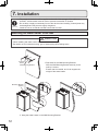
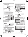
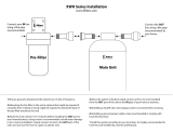
7.
Installation
Mounting the Water Heater to the wall
• The weight of the device will be applied to the wall. If the strength of the wall is not
sufcient, reinforcement must be done to prevent the transfer of vibration.
• Do not drop or apply unnecessary force to the device when installing. Internal parts may
be damaged and may become highly dangerous.
• Install the unit on a vertical wall and ensure that it is level.
• When installing with bare hands, take caution to not inict injury.
• Be careful not to hit electrical wiring, gas, or water piping while drilling holes.
CAUTION
Be sure to do
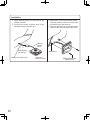
2. Hang the water heater on the Wall Mounting Bracket.
Mounting Bracket
(Upper)
Anchoring
Screw
Wall Mounting Bracket
Hang
1. Drill holes for the Wall Mounting Bracket.
Afx the Wall Mounting Bracket securely to the
wall by 5 screws.
Ensure that it is leveled, and it can support the
weight of the water heater.

13
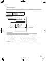
* Do not change any other dip switches.
High Elevation Adjustment
Dip Switches
#6#5
2,001 - 4,000 ft (611 - 1,220m)
0 - 2,000 ft (0 - 610m)
ON=OFF=
4,001 - 7,000 ft (1,221 - 2,135m)
7,001 - 10,000 ft (2,136 - 3,050m)
Elevation Adjustment Above 2,000ft
• Adjust the dip switches as illustrated in the table to the below if this water heater is installed at an altitude of
2000 ft. (610m) or higher.
• Disconnect power to the water heater before changing the dip switches.
Failure to perform this step will result in a "73" code displayed on the remote controller and a cease in operation.
If this occurs, disconnect, then reconnect power to the water heater to reset the system.
Note : Please refer to page 28 for the location of the dip switch bank.
3. Afx the Mounting Bracket (Lower)
to the wall by 2 screws.
Mounting Bracket
(Lower)
Anchoring Screw
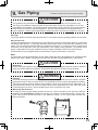
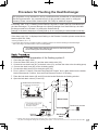
Filling the condensate container with water
The condensate container can be lled before connecting the vent pipe.
Filling the condensate container before vent pipe installation.
DANGER
Prior to initial start up, make sure that you ll the condensate container with water.
This is to prevent dangerous exhaust gases from entering the building.
Failure to ll the condensate container could result in severe personal injury or
death.
Please follow one of the procedures described below to ensure that the condensate container is lled with water.
1) Fill the condensate container by pouring
approx. 10 oz.(280ml) of water into the exhaust accessory
on the top of the appliance as illustrated below.
Or, if the vent pipe has already been installed:
2) After installing the drain pipe, make sure that the area around the appliance is well ventilated; open a
window or a door if necessary.
Then, operate the unit and verify that condensate is coming out of the drain pipe.
(During normal use of the water heater, condensate will begin to discharge from the drain pipe within
15 minutes of use. However, depending on the season and/or installation site conditions, it may take longer.)
10 oz.
280ml
Intake
Exhaust

14
•
This appliance has been designed to be vented
with either 2" (50mm) or 3" (75mm) PVC or
CPVC pipe.
Do not exceed the following maximum vent lengths:
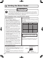
8.
Venting the Water Heater
WARNING
Be sure to do
CARBON MONOXIDE POISONING
Follow all vent system requirements in accordance with relevant local or state regulation,
or, in the absence of local or state code, in the U.S. to the National Fuel Gas Code ANSI
Z233.1/NFPA 54 – latest edition, and in Canada, in accordance with the Natural Gas and
Propane Installation Code CSA B149.1 – latest edition.
• This is a Category IV appliance.
Only vent materials approved for use with
Category IV appliances should be used.
• Under normal conditions, this appliance will not
produce an exhaust ue temperature in excess
of 149°F (65°C) and schedule 40 PVC pipe
may be used as the vent material. If required by
local code, use schedule 40 or 80 CPVC. Refer
to page 16 for additional requirements.
• Make sure the vent system is gas tight and
will not leak.
• Support the vent pipe with hangers at regular
intervals as specied by these instructions or
the instructions of the vent manufacturer.
•
This appliance is suitable for Common Vent System.
To make a Common Vent System, optional
accessories are required. Contact Noritz
America at http://support.noritz.com/ or 1-866-
766-7489 for details.
•
The total vent length including horizontal & vertical
vent runs should be no less than 3' (0.9m).
•
Do not store hazardous or ammable substances
near the vent termination and check that the
termination is not blocked in any way.
• Steam or condensed water may come out
from the vent termination. Select the location
for the termination so as to prevent injury or
property damage.
• If snow is expected to accumulate, take care
the end of the pipe is not covered with snow
or hit by falling lumps of snow.
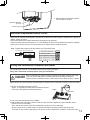
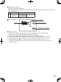
1. Continue to insert the Vent Pipe until it reaches to the
base of the unit Exhaust and Intake Flue.
(The Vent Pipe will be inserted approximately
2.3"(60mm).)
2. Secure the Vent Pipe by tightening the band using a
screwdriver
(The tightening torque shall be between 16 and 20 in lb.)
General Requirements
How to tighten the Vent Pipe
Maximum Vent Lengths
Clearances
PVC or CPVC has been approved for use on this
appliance with zero clearance to combustibles.
No. of Elbows
Max. Straight Vent Length*
8 N/A 60' (18.0m)
7 N/A 63' (18.9m)
6 12' (3.6m) 69' (20.7m)
5 18' (5.4m) 75' (22.5m)
4 27' (8.1m) 78' (23.4m)
3 36' (10.8m) 84' (25.2m)
2 42' (12.6m) 90' (27.0m)
1 51' (15.3m) 93' (27.9m)
Pipe diameter 2" (50mm) 3" (75mm)
Indoor Installation when using PVC/CPVC material
* Not including the termination
Refer to pages 20 for max. vent lengths
When using PVC Concentric Termination.
Exhaust and
Intake Flue
Vent Pipe
Screwdriver
-Flat head
-Box wrench(5/16")

15
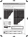
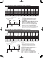
Maximum Vent Length Adjustment Dip switches
Number of
pieces**
Number of
pieces**
Short length using
3" (75mm)
pipe
Short length using 2" (50mm)pipe
Long length using 2" (50mm)pipe
Long length using
3" (75mm)
pipe
** Table assumes straight vent pieces are 3’ (0.9m) each.
Shorter or longer vent pieces may also be used up to
the maximum allowed vent length.
** Table assumes straight vent pieces are 3’ (0.9m) each.
Shorter or longer vent pieces may also be used up to
the maximum allowed vent length.
Vent length condition
࠙
Dip Switch Adjustment
ࠚ
Dip switches
1
#7 #8
ON=OFF=
2
3
4
2” Pipe 3” Pipe
* Not including the termination.
* Not including the termination.
• Do not change any other dip switches.
• Please refer to page 28 for the location of the dip switch bank.
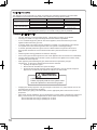
[Vent length example]
Using 2"(50mm) pipe, Vent length = 42 ft. (12.6m) and Two 90° elbows
→Set at " long length using 2" (50mm) pipe" condition.
3 0.9 1
6 1.8 2
9 2.7 3
12 3.6 4
15 4.5 5
18 5.4 6
21 6.3 7
24 7.2 8
27 8.1 9
30 9.0 10
33 9.9 11
36 10.8 12
39 11.7 13
42 12.6 14
45 13.5 15
48 14.4 16
51 15.3 17
54 16.2 18
57 17.1 19
60 18.0 20
6
Vent length* Elbows
ft m0 45123
30.9 1
61.8 2
92.7 3
12 3.64
15 4.55
18 5.46
21 6.37
24 7.28
27 8.19
30 9.010
33 9.911
36 10.8 12
39 11.7 13
42 12.614
45 13.515
48 14.416
51 15.317
54 16.218
57 17.119
60 18.020
63 18.921
66 19.822
69 20.723
72 21.624
75 22.525
78 23.426
81 24.327
84 25.228
87 26.129
90 27.030
93 27.931
96 28.832
99 29.733
100 30.034
Vent length* Elbows
ft m0 5
678
1234
1
2
3
4
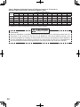
<Maximum Vent Length Congurations>
The unit can be adjusted to accommodate longer vent runs; refer to the below table to nd the
maximum vent length based on the number of elbows. Adjust the dip switches according to the vent
condition noted in the tables below.
Note:
By default, the unit has been set to the " 1 short length using 2" (50mm) pipe" condition. When adjusting
the dip switches for longer vent runs, the BTUH input of the appliance will be reduced by up to 9%.
• Disconnect power to the water heater before changing the dip switches. Failure to perform
this step will result in a "73" code displayed on the remote controller and a cease in operation
.
If this occurs, disconnect, then reconnect power to the water heater to reset the system.
The power must be unplugged when adjusting the dip switches to switch
the airow amount.

16
WARNING
CARBON MONOXIDE POISONING
Failure to properly seal the vent system could
cause flue products to enter the living space.
Item Material United States Canada
Exhaust Vent/Air Intake
Schedule 40 PVC ANSI/ASTM D1785
PVC-DWV ANSI/ASTM D2665
Schedule 40 CPVC ANSI/ASTM F441
Pipe Cement/Primer
PVC ANSI/ASTM D2564
CPVC ANSI/ASTM F493
PVC/CPVC Installation Instructions
• Use
• Covering non-metallic vent pipe and fittings with thermal insulation is prohibited.
only solid PVC or CPVC schedule 40 pipe. Cellular foam core piping is not allowed.
•
•
In Canada, plastic vent systems must be certified to ULC S636. The components of the certified
vent system must not be interchanged with other vent systems or unlisted pipe/fittings.
• In Canada, specified primers and glues of the ULC S636 certified vent system must be from a
single system manufacturer and not intermixed with other system manufacturer’s vent system
parts.
• Follow all general venting guidelines as outlined on this page.
• The pipe shall be installed so that the first 3’ (0.9m) of pipe from the appliance flue outlet is readily
accessible for visual inspection.
• When preparing and assembling the pipe, follow instructions as provided by the pipe
manufacturer. In general, the following practices must be observed:
o Squarely cut all pieces of pipe.
o Remove all burs and debris from joints and fittings.
o All joints must be properly cleaned, primed, and cemented. Use only cement and primer
approved for use with the pipe material as outlined in the above table.
•
• PVC or CPVC pipe has been approved for use on this appliance with zero clearance to combustibles.
All piping must be fully supported. Use pipe hangers at a minimum of 3’ (0.9m) intervals. Do not use
the water heater to support the vent piping.
2" or 3" schedule 80 pipe may also be used on this appliance, however the BTUH input of the
appliance will be reduced by up to 9%.
Venting With PVC or CPVC
This appliance can be vented with non cellular core plastic pipe materials as specified in the below table.
Vent installations in Canada which utilize plastic vent systems must comply with ULC S636.
•
•A bird screen must be installed on the vent terminations to prevent debris or animals from entering the
piping. These screens are not supplied with the water heater and must be purchased separately,
- Part # VT2-PVCS when using 2" (50mm) PVC or CPVC
- Part # VT3-PVCS when using 3" (75mm) PVC or CPVC
When attaching the piping to the water heater, use the appropriate primer and cement to ensure a
proper seal.
U
CSA B137.3
CSA B181.2
CSA B137.3
LC S636 Certified
Materials Only
Note: Use of cellular core PVC (ASTM F891), cellular core CPVC, or
Radel (polyphenylsulfone) in non-metallic venting system is prohibited.
R

17
V
ertical Vent Termination - PVC/CPVC Material Only
•
•
•
•
•
•
•
•
•
Horizontal Vent Termination - PVC/CPVC Material Only (when using PVT-HL termination)
Hanger
Straps
**1' mini
* Not supplied with water heater,
order separately.
mum recommended,
but not required.
3 ft. Min.
Firestop Firestop
Firestop/Support
Roof
Flashing
Roof
Flashing
Hanger
Strap
**1'
Minimum
**1'
Minimum
Support
Slope the Vent
Upward
Slope vent
Upwards
Intake
Exhaust
12" over
maximum
snow level
12" over
maximum
snow level
Insert Bird
Screen* in
End of 90 Elbow
Storm
Collar
Storm
Collar
•
Make sure to keep a distance of 3' (0.9m) or wider between the intake and exhaust when installing the vent piping.
If 3’ (0.9m) distance between Intake and Exhaust cannot be ensured, the installation can be carried out only
in the installation method shown in page 18.
•
Terminate at least 12" (300mm) above grade or above snow line.
•
Slope the horizontal vent 1/4" upwards for every 12" (300mm) toward the termination.
•
Use a condensation drain if necessary.
•
In the Commonwealth of Massachusetts a carbon monoxide detector is required for all side wall horizontally vented
gas fuel equipment. Please refer to Technical Bulletin TB 010606 for full installation instructions.
As illustrated on the left, make sure to keep a distance
of 3' (0.9m) or wider between the intake and exhaust
when installing the vent piping.
Terminate at least 3’ (0.9m) from the combustion air
intake of any appliance and any other building opening.
Enclose exterior vent systems below the roof line to limit
condensation and protect against mechanical failure.
When the vent penetrates a floor or ceiling and is not
running in a fire rated shaft, a firestop and support is
required.
When the vent termination is located not less than
8' (2.4m) from a vertical wall or similar obstruction,
terminate above the roof at least 2' (0.6m), but not
more than 6' (1.87m), in accordance with the National
Fuel Gas Code ANSI Z223.1/NFPA 54 or Natural Gas
and Propane Installation Code CSA B149.1.
Provide vertical support every 3' (0.9m) or as required
by the vent pipe manufacturer's instructions.
A short horizontal section is recommended to prevent
debris from falling into the water heater.
When using a horizontal section, slope the horizontal
vent 1/4” upwards for every 12” (300mm) toward the
termination to drain condensate.
When using 3" (75mm) pipe, it will be necessary to use
2" (50mm) ×3" (75mm) increaser couplings and a short
section 2" (50mm) pipe to connect the Exhaust and
Intake Flue of the Water Heater. Use maximum
6" (150mm) section of pipe to make the connection
between the increaser couplings and the Exhaust and
Intake Flue of the Water Heater.
Insert Bird
Screen* in
End of 90 Elbow
When choosing intake and exhaust terminations, you must use the
same type of elbow (i.e. both 90° elbows).
This will help with proper combustion by putting both terminations in
the same pressure zone.
When choosing intake and exhaust terminations, you must use the
same type of elbow (i.e. both 90° elbows).
This will help with proper combustion by putting both terminations in
the same pressure zone.
Insert Bird Screen*
in End of 90 Elbow
3” Min.
Intake
3" (75mm)
Interior Wall
Ceiling
Exhaust
3" (75mm)
Slope the Vent
Upward
Hanger Straps
* 1' Minimum recommended, but not required.
** 3" (75mm) pipe and 2"×3"
Increaser couplings
require when using PVT-HL.
Increaser Couplings must be used just behind
the water heater.
* 1' Minimum
When choosing intake and exhaust terminations, you must use the same type of
The PVC/CPVC elbow may be used in place of
PVT-HL as the horizontal vent termination.
elbow (i.e. both 90 - elbows).
This will help with proper combustion by putting both terminations in the same pressure zone.
Ӎ 3ft. Min
Intake
Exhaust
Exterior Wall
PVT-HL
3"(75mm)
12"(300mm)
above grade or
above snow line
**2"×3" Increaser
coupling
Exhaust
2" (50mm)
Intake
2" (50mm)
* Not supplied with water
heater, order separately.
** 1' Minimum recommended,
but not required.
2"×3" increaser couplings require
when using 3" (75mm) pipe.
2" pipe
3" pipe
2"×3" Increaser
coupling
Vent Pipe Installation

18
Vent Pipe Installation
Alternate Horizontal Vent Termination- PVC/CPVC Materials Only
Ensure at least 2ft (0.6m) or more distance
between intake pipe and exhaust pipe.
The distance is measured at inside of pipe
to inner dimension.
•
Upper side is exhaust, lower side is intake.
The reverse orientation is not allowed.
Ensure at least 1ft (0.3m) or more distance
between intake pipe and exhaust pipe.
The distance is measured at the outlets of
intake port (terminal) and exhaust port (terminal).
•
•
The side distant from wall is intake, the side
near the wall is exhaust.
The reverse orientation is not allowed.
Ensure at least 1ft (0.3m) or more distance
between intake pipe and exhaust pipe.
The distance is measured at inside of pipe to
inner dimension.
•
•
•
WARNING
If the distance between the air inlet and exhaust vent terminations is too short, the water heater
will draw in the exhaust gases through the intake. There is a risk of inadequate combustion air
for the water heater, increasing Carbon Monoxide (CO) emissions and noise due to vibration.
•
Termination elbows must be oriented vertically, pointing directly downward. Attempts to prevent
exhaust air from entering the air inlet by angling termination elbows in directions other than
directly downward will increase the risk of freezing.
•
Reversing the air intake and exhaust pipes is not allowed.
Carbon Monoxide (CO) emissions and noise due to vibration will increase.
* When 3’
(0.9m) distance between Intake and Exhaust cannot be ensured.
* Can not use Hood termination (PVT
-HL)
* Insert the bird screen. 90° elbow vertical setting (downward).
* Ensure at least 3ft (0.9m) or more distance between the near edge of the air intake pipe or exhaust pipe to the
inside corner of a wall.
* Intake and exhaust should face the same direction. Intake and exhaust should keep the same pressure zone.
㸦between outside
wall and termination)
㸦between outside
wall and termination)
㸦
between outside
wall and termination)
5.1"
Exhaust
Intake
Ӎ
2ft. Min
Ӎ3" Min
Interior View
Exterior View
Interior View
Exterior View
Interior View
Exterior View
5.1"
Exhaust
Intake
Ӎ1ft. Min
Ӎ3" Min
5.1"
Ӎ1ft. Min
Ӎ3" Min
Exhaust
Intake

19
Horizontal
Hanger
Straps
Strap
Slope the Vent
Upward
Intake
2" (50mm)
or
3" (75mm)
Exhaust
2" (50mm)
or
3" (75mm)
1" (25mm) to
2" (50mm)
Insert Bird Screen** in End of Termination.
** Not supplied with water heater.
It is included in PVC Concentric Termination.
PVC-2CT
or
PVC-3CT *
* 3" (75mm) pipe and 2"-3" increaser couplings
require when using PVC-3CT.
Increaser couplings must be used just behind
the water heater.
2" pipe
3" pipe
2"×3"Increaser
coupling
e.g.) PVC-2CT installation
•
•
•
•
•
•
•
•
•
•
•
The concentric termination may be shortened, but not lengthened from its original factory supplied length.
2"(50mm) or 3" (75mm) PVC or CPVC pipe may be used with the concentric termination.
Maintain the same vent pipe diameter from the water heater flue to the termination.
Do not exceed the maximum vent lengths as shown on next page 20.
When using 3" (75mm) pipe, it will be necessary to use 2"(50mm)×3" (75mm) increaser couplings and a short section
2" (50mm) pipe to connectthe Exhaust and Intake Flue of the Water Heater. Use maximum 6" (150mm) section of
pipe to make the connection between the increaser couplings and the Exhaust and Intake Flue of the Water Heater.
There must be a 1" (25mm) to 4" (100mm) clearance between the outside wall and the air intake section of the
termination as illustrated below.
Install a securing strap to prevent movement of the termination.
Terminate at least 12" (300mm) above grade or above snow line.
For vertical installation, terminate at least 3’ (0.9m) from the combustion air intake of any appliance and any other
building opening.
Slope the horizontal vent 1/4" upwards for every 12" (300mm) toward the termination.
Use a condensation drain if necessary.
In the Commonwealth of Massachusetts a carbonmonoxide detector is required for all side wall
horizontally vented gas
fuel equipment. Please refer to Technical Bulletin TB 010606 for full installation instructions
Continue to next page
PVC Concentric Termination

20
Vertical
12" (30cm)
Intake
2" (50mm)
or
3" (75mm)
Exhaust
2" (50mm)
or
3" (75mm)
Plastic Rain Cap*
(PRC-1)
*Not supplied with water
heater, order separately.
Increaser coupling**
**Not supplied with water heater,
order separately.
PVC-2CT
or
PVC-3CT***
*** 3" (75mm) pipe and 2"×3"Increaser couplings
require when using PVC-3CT.
Increaser couplings need to be used just prior
to PVC-3CT.
2" pipe
3" pipe
3" pipe
2"×3"Increaser
coupling
e.g.) PVC-2CT installation
Maximum Vent length when using PVC-2CT or PVC-3CT
Number of
pieces**
Number of
pieces**
Short length using
3" (75mm)
pipe
Short length using 2" (50mm)pipe
Long length using 2" (50mm)pipe
Long length using
3" (75mm)
pipe
** Table assumes straight vent pieces are 3’ (0.9m) each.
Shorter or longer vent pieces may also be used up to
the maximum allowed vent length.
** Table assumes straight vent pieces are 3’ (0.9m) each.
Shorter or longer vent pieces may also be used up to
the maximum allowed vent length.
Vent length condition
࠙
Dip Switch Adjustment
ࠚ
Dip switches
1
#7 #8
ON= OFF=
2
3
4
2” Pipe 3” Pipe
* Not including the termination.
* Not including the termination.
3 0.9 1
6 1.8 2
9 2.7 3
12 3.6 4
15 4.5 5
18 5.4 6
21 6.3 7
24 7.2 8
27 8.1 9
30 9.0 10
33 9.9 11
36 10.8 12
39 11.7 13
42 12.6 14
45 13.5 15
48 14.4 16
51 15.3 17
54 16.2 18
57 17.1 19
60 18.0 20
6
Vent length* Elbows
ft m0 45123
30.9 1
61.8 2
92.7 3
12 3.64
15 4.55
18 5.46
21 6.37
24 7.28
27 8.19
30 9.010
33 9.911
36 10.8 12
39 11.7 13
42 12.614
45 13.515
48 14.416
51 15.317
54 16.218
57 17.119
60 18.020
63 18.921
66 19.822
69 20.723
72 21.624
75 22.525
78 23.426
81 24.327
84 25.228
87 26.129
90 27.030
93 27.931
96 28.832
99 29.733
100 30.034
Vent length* Elbows
ft m0 56781234
1
2
1
3
4
3" (75mm) pipe and 2"×3" increaser
coupling requires when using PRC-1.
PRC-1
3" (75mm) pipe
2" (50mm) pipe
2"×3" increaser coupling
Page is loading ...
Page is loading ...
Page is loading ...
Page is loading ...
Page is loading ...
Page is loading ...
Page is loading ...
Page is loading ...
Page is loading ...
Page is loading ...
Page is loading ...
Page is loading ...
Page is loading ...
Page is loading ...
Page is loading ...
Page is loading ...
Page is loading ...
Page is loading ...
Page is loading ...
Page is loading ...
Page is loading ...
Page is loading ...
Page is loading ...
Page is loading ...
Page is loading ...
Page is loading ...
Page is loading ...
Page is loading ...
Page is loading ...
Page is loading ...
Page is loading ...
Page is loading ...
Page is loading ...
Page is loading ...
Page is loading ...
Page is loading ...
Page is loading ...
-
 1
1
-
 2
2
-
 3
3
-
 4
4
-
 5
5
-
 6
6
-
 7
7
-
 8
8
-
 9
9
-
 10
10
-
 11
11
-
 12
12
-
 13
13
-
 14
14
-
 15
15
-
 16
16
-
 17
17
-
 18
18
-
 19
19
-
 20
20
-
 21
21
-
 22
22
-
 23
23
-
 24
24
-
 25
25
-
 26
26
-
 27
27
-
 28
28
-
 29
29
-
 30
30
-
 31
31
-
 32
32
-
 33
33
-
 34
34
-
 35
35
-
 36
36
-
 37
37
-
 38
38
-
 39
39
-
 40
40
-
 41
41
-
 42
42
-
 43
43
-
 44
44
-
 45
45
-
 46
46
-
 47
47
-
 48
48
-
 49
49
-
 50
50
-
 51
51
-
 52
52
-
 53
53
-
 54
54
-
 55
55
-
 56
56
-
 57
57


Noritz GQ-C2859WX-FF US NG Operating instructions
- Category
- Water heaters & boilers
- Type
- Operating instructions
- This manual is also suitable for
Ask a question and I''ll find the answer in the document
Finding information in a document is now easier with AI
Related papers
-
Noritz America GQ-C2859WX-FF US LP User manual
-
Noritz America EGQ-C3260WX-FF US NG User manual
-
Noritz NCC199CDV Owner's manual
-
-
-
-
Noritz America NRCP982-DV-LP Operating instructions
-
-
-
Other documents
-
 THERMALUX NERC11DV–LP Operating instructions
-
AlorAir Sentinel HDi65 User manual
-
 THERMALUX NERC98-DV-LP Operating instructions
-
-
-
-
 THERMALUX NERC98-DV-LP User manual
-
State Water Heaters 21 Owner's Manual And Installation Manual
-
 THERMALUX NERC11DV–LP User manual
-
 IFILTER XWH-1000 User manual


