Page is loading ...

Potential dangers from accidents during installation and use are divided into the following three
categories. Closely observe these warnings, they are critical to your safety.
Prohibited
Disconnect
Power
Ground
Be sure to do
WARNING:
If the information in this manual is not followed exactly, a re or explosion may result
causing property damage, personal injury or death.
NORITZ AMERICA
CORPORATION
Installation Manual
CONDENSING TANKLESS GAS WATER HEATER
NRC663-FSV (EZTR40)
(Indoor Installation)
DANGER indicates an imminently hazardous situation which,
if not avoided, will result in death or serious injury.
WARNING indicates a potentially hazardous situation which,
if not avoided, could result in death or serious injury.
CAUTION indicates a potentially hazardous situation which,
if not avoided, may result in minor or moderate injury.
DANGER
WARNING
CAUTION
SBB809L
Rev. 08/14
Requests to Installers
• In order to use the water heater safely, read this installation manual carefully, and follow the
installation instructions.
• Failures and damage caused by erroneous work or work not as instructed in this manual are not
covered by the warranty.
•
Check that the installation was done properly in accordance with this Installation Manual upon completion.
•
After completing installation, please either place this Installation Manual in a plastic pouch and
attach it to the side of the water heater (or the inside of the pipe cover or recess box if applicable),
or hand it to the customer to retain for future reference. Also, be sure to ll in all of the required
items on the warranty and to hand the warranty to the customer along with the Owner's Guide.
CAUTION
FOR USE IN RESIDENTIAL APPLICATIONS.
Installation must conform with local codes, or in the absence of
local codes, the National Fuel Gas Code, ANSI Z223.1/NFPA 54-
latest edition.
Noritz America reserves the right to discontinue, or change at any
time, the designs and/or specifications of its products without
notice.
Low NOx
Approved by
SCAQMD
14 ng/J or 20 ppm
(Natural Gas Only)
SBB809L_001_038_E_J.indd 1 14/08/05 16:13

2
1.
Included Accessories
The following accessories are included with the unit.
Check for any missing items before starting installation.
Q’ty
ShapePart
Anchoring Screw
1
each
Part Shape
Q’ty
5
1
Remote Controller
(See p. 28)
Remote Controller
Cord (10ft (3m))
1
2.
Optional Accessories
The accessories listed below are not
included with the units, but may be necessary
for installation.
Q’ty
ShapePartPart Shape
Q’ty
Remote Controller
Cord (26ft (8m))
1
1
each
Isolation Valves*
(includes pressure
relief valve)
Owner's Guide, Warranty,
Installation Manual
(this document)
1N-FlexKit2"-35
Note: Additional vent pieces are available; consult the latest product catalogue for details.
1
Neutralizer
(NC-1)
* Isolation valves are necessary for ushing the Heat Exchanger.
They allow for easy ushing of the system.
SBB809L_001_038_E_J.indd 2 14/08/05 16:13

3
Check the Gas
• Check that the rating plate indicates the
correct type of gas.
• Check that the gas supply line is sized for
120,000 Btuh.
Check the Power
• The power supply required is 120VAC, at 60Hz.
Using the incorrect voltage may result in re or electric shock.
Use Extreme Caution if Using With a Solar Pre-Heater
• Using this unit with a solar pre-heater can lead to unpredictable output temperatures and
possibly scalding. If absolutely necessary, use mixing valves to ensure output temperatures do
not get to scalding levels.
3.
Before Installation
Checkup
• Check the xing brackets and vent pipe yearly for damage or wear. Replace if necessary.
DANGER
Do Not Use Equipment for Purposes Other Than Those Specied
• Do not use for other than increasing the temperature of the water supply, as unexpected accidents
may occur as a result.
Check Water Supply Quality
• If the water supply is in excess of 12 grains per gallon (200 mg/L) of hardness, acidic or otherwise
impure, treat the water with approved methods in order to ensure full warranty coverage.
WARNING
CAUTION
Precautions on Vent Pipe Replacement
• The vent system will almost certainly need to be replaced when this appliance is being installed.
Only use vent materials that are specied in this Installation Manual for use on this appliance.
Refer to the "Vent Pipe Installation" section for details. If the exible polypropylene pipe is already
installed, replace to the new exible polypropylene pipe.
Improper venting may result in res, property damage or exposure to Carbon Monoxide.
Snow Precaution
• If this product will be installed in an area where snow is known to accumulate, protect the vent
termination from blockage by snow drifts or damage from snow falling off of roofs.
SBB809L_001_038_E_J.indd 3 14/08/05 16:13

4
4.
Choosing Installation Site
* Locate the appliance in an area where leakage from the unit or connections will not result in damage
to the area adjacent to the appliance or to the lower oors of the structure. When such locations
cannot be avoided, it is recommended that a suitable drain pan, adequately drained, be installed
under the appliance. The pan must not restrict combustion air ow.
• Locate the vent terminal so that there are no obstacles around the termination and so that exhaust
can't accumulate. Do not enclose the termination with corrugated metal or other materials.
• Avoid places where res are common, such as those where gasoline, benzene and adhesives
are handled, or places in which corrosive gases (ammonia, chlorine, sulfur, ethylene compounds,
acids) are present.
Using the incorrect voltage may result in re or cracking.
• Avoid installation in places where dust or debris will accumulate.
Dust may block the air-supply opening, causing the performance of the device fan to drop and
incomplete combustion to occur as a result.
• Avoid installation in places where special chemical agents
(e.g., hair spray or spray detergent) are used.
Ignition failures and malfunction may occur as a result.
• Carbon Monoxide Poisoning Hazard. Do not install this water heater in a mobile home, recreational
vehicle or on a boat.
• The water heater is designed for indoor installation only. Never install it
outdoors or in a bathroom, it may be damaged or a re may be caused.
• Consult with the customer concerning the location of installation.
• Install the water heater in an area that allows for the proper clearances
to combustible and noncombustible construction. Consult the rating
plate on the appliance for proper clearances.
• Do not install the water heater in a place where it may be threatened by
falling objects, such as under shelves.
• Do not install the water heater in a place where the inside/outside
temperature is below 32°F (0°C).
• The water heater must be installed in a place where exhaust pipes can
be installed as directed.
• Do not install the water heater where the exhaust will blow on outer walls
or material not resistant to heat. Also consider the surrounding trees and
animals.
The heat and moisture from the water heater may cause discoloration of
walls and resinous materials, or corrosion of aluminum materials.
DANGER
WARNING
CAUTION
Prohibited
SBB809L_001_038_E_J.indd 4 14/08/05 16:13

5
• Avoid installation above gas ranges or stoves.
• Avoid installation between the kitchen fan and stove. If oily
fumes or a large amount of steam are present in the installation
location, take measures to prevent the fumes and steam from
entering in the equipment.
• Install in a location where the exhaust gas ow will not be affected
by fans or range hoods.
• Take care that noise and exhaust gas will not affect neighbors.
Avoid installation on common walls as the unit will make some
operational noises while it is running.
• Make sure that the location allows installation of the exhaust
vent as specied.
• Avoid installation where the exhaust vent terminal will be exposed
to excessive winds.
• Before installing, make sure that the exhaust ue termination will
have the proper clearances according to the National Fuel Gas
Code (ANSI Z223.1).
State of California: The water heater must be braced, anchored or strapped to avoid moving during an
earthquake. Contact local utilities for code requirements in your area or call: 1-866-766-7489 and
request instructions.
Be sure to do
Prohibited
CAUTION
The Commonwealth of Massachusetts: The water heater can be used for hot water only and not in a
combination of domestic and space heating.
For Venting Manufacturers Requirements, see websites listed below:
Noritz N-Flex vent kit www.noritz.com
http://support.noritz.com/
SBB809L_001_038_E_J.indd 5 14/08/05 16:13

6
5.
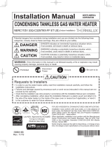
Installation Clearances
Before installing, check for the following:
Install in accordance with relevant building and mechanical codes, as well as any local, state or
national regulations, or in the absence of local and state codes, to the National Fuel Gas Code ANSI
Z223.1/NFPA 54 – latest edition for detailed requirements.
WARNING
Item
Distance from combustibles
• Maintain the following clearances
from both combustible and
non-combustible materials.
Check Illustration
• If possible, leave 8" (200mm) or more
on either side of the unit to facilitate
inspection.
• If possible, leave 24" (600mm) or more in
front of the unit to facilitate maintenance
and service if necessary.
• If possible, leave 3" (75mm) or more
above and below the vent pipe to facilitate
inspection and repair if necessary.
Securing of space for
repair/inspection
24" (600mm)
or more
Distance from the side
3" (75mm) or more
4" (100mm) or more
3" (75mm) or more
8" (200mm)
or more
8" (200mm)
or more
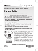
<When the indoor air supply>
• If the unit will be installed in the vicinity of
a permanent kitchen range or stove that
has the possibility of generating steam
that contains fats or oils, use a dividing
plate or other measure to ensure that the
unit is not exposed to air containing such
impurities.
*
The dividing plate should be of noncombustible
material of a width greater than the water
heater.
Exhaust hood
Range
Dividing plate
Water
heater
Cooking Equipment
▲The illustration is an example. Please check with the actual water heater about the position of piping, and form.
3" (75mm) or more
12" (300mm)
or more
SBB809L_001_038_E_J.indd 6 14/08/05 16:13

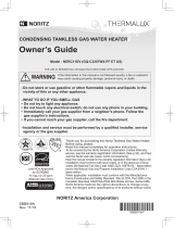
7
DescriptionRef
A=
Clearance above grade, veranda, porch, deck, or balcony
B=
Clearance to window or door that may be opened
C=
Clearance to permanently closed window
D=
Vertical clearance to ventilated soffit located above the
terminal within a horizontal distance of 2 feet (61 cm)
from the center line of the terminal
E=
Clearance to unventilated soffit
F=
Clearance to outside corner
G=
Clearance to inside corner
H=
Clearance to each side of center line extended above
meter/regulator assembly
I=
Clearance to service regulator vent outlet
J=
Clearance to nonmechanical air supply inlet to building or
the combustion air inlet to any other appliance
K=
Clearance to a mechanical air supply inlet
L=
Clearance above paved sidewalk or paved driveway located
on public property
Clearance under veranda, porch, deck, or balcony
M=
1
In accordance with the current ANSI Z223.1 / NFPA 54 National Fuel Gas Code
* Clearance in accordance with local installation codes and the requirements of the gas supplier.
Clearance to opposite wall is 24 inches (60 cm).
*
*
*
*
*
*
*
*
3 ft (91 cm) above if within
10 ft (3 m) horizontally
*
12 in (30 cm)
4 ft (1.2 m) below or to side of opening;
1 ft (30 cm) above opening
4 ft (1.2 m) below or to side of opening;
1 ft (30 cm) above opening
US Non-Direct Vent Installations
1
Vent Terminal
D
E
B
B
F
B
A
G
H
I
C
B
M
K
J
B
B
L
Air Supply Inlet
Area Where Terminal
is Not Permitted
A
Clearance Requirements from Vent Terminations to Building Openings
* All clearance requirements are in accordance with ANSI Z21.10.3 and the National Fuel Gas Code,
ANSI Z223.1.
SBB809L_001_038_E_J.indd 7 14/08/05 16:13

8
6.
Installation
Securing to the wall
IllustrationCheck
4. Drill holes for the remaining four screws.
5. Hang the unit again by the rst screw, and then
insert and tighten the remaining four screws.
6. Take waterproong measures so that water does
not enter the building from screws mounting the
device.
• Make sure the unit is installed securely so that it will
not fall or move due to vibrations or earthquakes.
1. Drill a single screw hole, making sure to hit a stud.
2. Insert and tighten the screw and hang the unit by
the upper wall mounting bracket.
3. Determine the positions for the remaining four screws
(two for the top bracket and two for the bottom), and
remove the unit.
• The weight of the device will be applied to the wall. If the strength of the wall is not sufcient,
reinforcement must be done to prevent the transfer of vibration.
• Do not drop or apply unnecessary force to the device when installing. Internal parts may
be damaged and may become highly dangerous.
• Install the unit on a vertical wall and ensure that it is level.
• Do not install the water heater when the inside/outside temperature is below 40°F (5°C).
Locating Screw Holes
Mounting
Structure
• When installing with bare hands, take caution to
not inict injury.
• Be careful not to hit electrical wiring, gas, or water
piping while drilling holes.
Item
CAUTION
Be sure to do
Mounting Bracket
(upper)
Location of Screw Hole
Locating Screw Holes
Installations at Elevations
Above 2,000 ft.
• Adjust the DIP switches as illustrated in the table to
the right if this water heater is installed at an altitude
of 2000 ft. (610m) or higher.
• Disconnect power to the water heater before changing
the DIP switches. Failure to perform this step will result
in a "733" code displayed on the Display Window and
a cease in operation. If this occurs, disconnect, then
reconnect power to the water heater to reset the system.
Anchoring Screw
▲The illustration is an example. Please check with the actual water heater about the position of piping, and form.
* Do not change any other DIP switches.
* High elevation adjustment.
65
2,001 - 3,500 ft (611 - 1,050m)
0 - 2,000 ft (0 - 610m)
ON=OFF=
SBB809L_001_038_E_J.indd 8 14/08/05 16:13

9
Filling the condensate trap with water
DANGER
When initial start up, make sure that you perform the following procedures.
This is to prevent dangerous exhaust gases from entering the building.
Failure to following procedure could result in severe personal injury or death.
After installing the drain pipe, make sure that the area around the unit is well ventilated; open a window or a
door if necessary. Then, operate the unit and verify that condensate is coming out of the drain pipe. (During
normal use of the unit, condensate will begin to discharge from the drain pipe within 15 minutes of use.
However, depending on the season and/or installation site conditions, it may take longer.)
SBB809L_001_038_E_J.indd 9 14/08/05 16:13

10
Maximum Vent Lengths
• This appliance has been designed to be vented
with 2" exible polypropylene pipe.
Do not exceed the following maximum vent lengths:
Max. Straight Vent Length : 35' (10.5m)
Maximum allowable 45° elbows are 2 elbows
* Not including 45° adapter included in
N-FlexKit2"-35
* No 90° elbows
* Not including the termination.
* Refer to N-FlexKit2"-35 installation manual for
additional requirements.
7.
Vent Pipe Installation
(Indoor Installation Only)
WARNING
Be sure to do
CARBON MONOXIDE POISONING
Follow all vent system requirements in accordance with relevant local or state regulation,
or, in the absence of local or state code, in the U.S. to the National Fuel Gas Code ANSI
Z233.1/NFPA 54 – latest edition.
• Under normal conditions, this appliance will
not produce an exhaust flue temperature in
excess of 149°F.
Refer to page 12 for additional requirements.
• Make sure the vent system is gas tight and
will not leak.
• Do not common vent or connect more than
one appliance to this venting system.
•
The total vent length including vertical vent runs
should be no less than 5' (1.5m).
•
Do not store hazardous or ammable substances
near the vent termination and check that the
termination is not blocked in any way.
• Steam or condensed water may come out
from the vent termination. Select the location
for the termination so as to prevent injury or
property damage.
• If snow is expected to accumulate, take care
the end of the pipe is not covered with snow
or hit by falling lumps of snow.
General Requirements
Clearances
2" exible polypropylene pipe has been approved
for use on this appliance with zero clearance to
combustibles.
• Do not install the water heater when the inside/outside temperature is below 40°F (5°C).
Be sure to do
SBB809L_001_038_E_J.indd 10 14/08/05 16:13

11
* Do not change any other DIP switch.
78 Vent Length
15' (1.5m) 13' (3.9m)
13' (3.9m) 23' (6.9m)
23' (6.9m) 29' (8.7m)
29' (8.7m) 35' (10.5m)
Minimum length
Short length
Long length
Maximum length
1
2
3
4
ON=OFF=
The power must be unplugged when
adjusting the DIP switch to switch the
airow amount.
The unit can be adjusted to accommodate longer vent runs; refer to the below table to nd the
maximum vent length. Adjust the DIP switch according to the vent condition noted in the tables below.
Maximum Vent Length Adjustment DIP switch
- Maximum length = 18 ft. (5.4m)
(with DIP switch set at "short length" condition)
- Maximum length = 30 ft. (9.0m)
(with DIP switch set at "Maximum length" condition)
[Maximum Vent Length Example]
• Disconnect power to the water heater before changing the DIP switch. Failure to perform
this step
will result in a "733" code displayed on the Display Window and a cease in operation
.
If this occurs, disconnect, then reconnect power to the water heater to reset the system.
<Maximum Vent Length Congurations>
SBB809L_001_038_E_J.indd 11 14/08/05 16:13

12
Venting Installation Instructions (General Information)
Property damage, personal injury or death can result if these instructions are not followed.
They are a guide for professional installers generally familiar with the installation and maintenance of
heating equipment and related vent systems.
・
Only manufacturer specied vent parts may be used for this equipment.
* Information regarding certication of "Flexible vent pipe and connections".
・
N-Flex kit may be used only in accordance with the installation manual included with the kit.
・
Do not install N-Flex vent kit where ambient air temperature can exceed 300°F(148°C).
・
N-Flex vent kit can be installed at zero clearance to combustible materials.
・
Appliances can be red up immediately after N-Flex vent kit is installed and inspected.
・
N-Flex vent systems expand and contract slightly during heating cycles and must be installed
following included instructions.
・
N-Flex vent kit cannot be painted.
・
When installing N-Flex vent, pitch is required as detailed in installation manual.
・
Keep N-Flex vent greater than 40°F (5°C) during installation.
Damage will occur if handled or installed at lower temperatures.
・
Do NOT intermingle any other venting material with allowable polypropylene venting
mentioned.
Standard(s)
UL-1738 Dated 10/4/2010 Standard for Safety for Venting Systems
ULC-S636-08 Standards for type BH Gas Venting Systems
Product PP Flexible 2", PP Single Wall Pipe 2"
Brand name InnoFlue Flex - Centrotherm
Models IFVL, IFSF, IANS, ISEL,
CARBON MONOXIDE POISONING
Failure to properly seal the vent system could
cause ue products to enter the living space.
WARNING
SBB809L_001_038_E_J.indd 12 14/08/05 16:13

13
Vertical Vent Termination with Polypropylene N-Flex system
Firestop
Firestop/Support
Roof
Flashing
Storm
Collar
Support
Alminum
flex pipe
Flexible
polypropylene pipe
•
•
•
•
•
Terminate at least 6' (1.8m) from the combustion air
intake of any appliance, and 3' (0.9m) from any other
building opening, gas utility meter, service regulator etc.
Enclose exterior vent systems below the roof line to limit
condensation and protect against mechanical failure.
When the vent penetrates a floor or ceiling and is not
running in a fire rated shaft, a firestop and support is
required.
When the vent termination is located not less than
8' (2.4m) from a vertical wall or similar obstruction,
terminate above the roof at least 2' (0.6m), but not
more than 6' (1.87m), in accordance with the National
Fuel Gas Code ANSI Z223.1/NFPA 54.
The aluminum flex pipe serves as protection against
damage.
Exhaust
This unit is suitable only for vertical vent.
WARNING
SBB809L_001_038_E_J.indd 13 14/08/05 16:13

14
• Provide two permanent openings to allow
circulation of combustion air.
• Make each opening 180 square inches if they
provide indoor air, and 100 square inches for
outdoor air.
• If the unit is installed in a mechanical closet,
provide a 24" (600mm) clearance in front of
the unit to the door.
• If combustion air will be provided through a
duct, size the duct to provide 60 cubic feet of
fresh air per minute.
Combustion Air
Openings supplying indoor air
9" (225mm)
20" (500mm)
9" (225mm)
20" (500mm)
▲The illustration is an example. Please check with the actual water heater about the position of piping, and form.
Supply combustion air to the units as per the National Fuel Gas Code, ANSI Z223.1.
Provide adequate combustion air so as to not create negative pressure within the builbing.
SBB809L_001_038_E_J.indd 14 14/08/05 16:13

15
Follow the instructions from the gas supplier.
8.
Gas Piping
Gas Type
The gas type indicated on the water heater rating plate (NG or LP) must match the type of gas being
supplied to the water heater.
Gas Conversions
If the gas type supplied does not match the gas type on the rating plate, contact your water heater supplier for
a replacement unit with the proper gas type. If a gas type conversion must be made, there are conversion
kits available for some models. [The conversion kit shall be installed by a qualied service agency in
accordance with the manufacturer’s instructions and all applicable codes and requirements of the
authority having jurisdiction. The qualied service agency is responsible for the proper installation of this
kit. Improper installation of this kit will void the warranty. Conversion kits will only be shipped directly to
the Distributor or Agency performing the conversion.]
Meter
The gas meter must be sized properly for the water heater and other gas appliances to operate properly.
Select a gas meter capable of supplying the entire btuh demand of all gas appliances in the building.
The guidelines and examples we have provided in this manual section are for reference only.
The sizing and installation of the gas system for this water heater, as with any gas appliance, is the
sole responsibility of the installer. The installer must be professionally trained to do such work and
must always follow all local and national codes and regulations. Gas line sizing calculations must
be performed for every installation. Please contact Noritz America at 866-766-7489 if you have
any questions or concerns.
CAUTION
Regulators
Ensure that all gas regulators used are operating properly and providing gas pressures within the specied
range of the water heater being installed. Excess gas inlet pressure may cause serious accidents.
CAUTION
Pressure
Check the gas supply pressure immediately upstream at a location provided by the gas company. Supplied
gas pressure must be within the limits shown in the specications section with all gas appliances operating.
The inlet gas pressure must be within the range specied. This is for the purposes of input adjustment. Low
gas pressure may cause a loss of ame or ignition failure at other appliances in the home, which may result
in unburned gas in the home. Serious accidents such as re or explosion may result.
Measuring Gas Pressure
In order to check the gas supply pressure to the unit, a tap is provided on the gas
inlet. Remove the 9/32” hex head/Philips screw from the tap, and connect a
manometer using a silicon tube. Open up at least 2 xtures and hold in the maximum
manifold pressure button on the circuit board. Please call Noritz for details.
WARNING
SBB809L_001_038_E_J.indd 15 14/08/05 16:13

16
Pressure Test
The appliance and its gas connections must be leak tested before placing the appliance in operation.
The appliance must be isolated from the gas supply piping system by closing its individual manual
shutoff valve during any pressure testing of the gas supply piping system at test pressures equal to
or less than ½ psig (3.5 kPa). We do not recommend pressure testing in excess of ½ psig (3.5kPa).
If it must be done, the appliance and its individual shutoff valve must be completely disconnected
from the gas supply piping system during the test process.
Pipe Sizing/Flexible Connectors
A gas shutoff valve must be installed on the supply line. Gas ex lines are not recommended unless
the minimum inside diameter is ¾” or greater and the rated capacity of the connector is equal to
or greater than the BTU capacity of the water heater. Gas piping shall be in accordance with local
utility company requirements and/or in the absence of local codes, use the latest edition of National
Fuel Gas Code (NFPA54GC), ANSI Z223.1. Size the gas line according to total btuh demand of the
building and length from the meter or regulator so that the following supply pressures are available
even at maximum demand.
WARNING
Natural Gas Supply Pressure
Min 4” WC
Max 10.5” WC
LP Gas Supply Pressure
Min 8” WC
Max 14” WC
Reference Tools & Sample Calculations
The tables and samples below are for reference only. The professional sizing and installing the gas
line should always run the appropriate calculations before all installations.
CAUTION
Which Table to Use
• For NG installations with the initial supply pressure at point of delivery (at the meter, for example) is
less than 8” WC, use the 0.5” WC pressure drop table (Table 1).
• For NG installations with the initial supply pressure at point of delivery is greater than or equal to 8”
WC, use the 3.0” pressure drop table (Table 2).
• For all LP installation use (Table 3)
The inlet pressure must be at least 5” WC for NG or 8” WC for LP for all appliances in the gas system.
If the inlet gas pressure drops below 5” WC for NG or 8” WC for LP, the heater may continue to operate,
but the other appliances in the house may experience ame loss or ignition failure, which can result in
gas leakage into the home. Refer to the NFPA 54 for details.
Please contact Noritz for details. For corrugated stainless steel tubing (CSST) capacity tables, please
consult with the manufacturer.
SBB809L_001_038_E_J.indd 16 14/08/05 16:13

17
Pipe
Size
Length (including ttings)
10' 20' 30' 40' 50' 60' 70' 80' 90' 100' 125'
(3m) (6m) (9m) (12m) (15m) (18m) (21m) (24m) (27m) (30m) (38m)
3/4" 360 247 199 170 151 137 126 117 110 104 92
1" 678 466 374 320 284 257 237 220 207 195 173
1 1/4" 1,390 957 768 657 583 528 486 452 424 400 355
1 1/2" 2,090 1,430 1,150 985 873 791 728 677 635 600 532
2" 4,020 2,760 2,220 1,900 1,680 1,520 1,400 1,300 1,220 1,160 1,020
2 1/2" 6,400 4,400 4,400 3,020 2,680 2,430 2,230 2,080 1,950 1,840 1,630
3" 11,300 7,780 7,780 5,350 4,740 4,290 3,950 3,760 3,450 3,260 2,890
4" 23,100 15,900 12,700 10,900 9,660 8,760 8,050 7,490 7,030 6,640 5,890
Table 1. For Less than 8” WC initial supply pressure
Maximum Natural Gas Delivery Capacity (0.5” Pressure Drop) [Schedule 40 Metalic Pipe]
Values in Table are in Cubic Feet of Gas per Hour (0.60 Specic Gravity, 0.5” Pressure Drop, inlet pressure less than 2psi). Contact your gas
supplier for BTU/Cubic Foot ratings. For simplication of your calculations, 1 Cubic Foot of Gas is approximately equivalent to 1000 BTU.
Instructions
1. Size each outlet branch starting from the furthest
using the Btuh required and the length from the meter.
2. Size each section of the main line using the length to
the furthest outlet and the Btuh required by everything
after that section.
Sample Gas Line
Sample Calculation - (Using 0.5” WC Pressure Drop Ta
ble)
Outlet A: 45' (13.5m) (Use 50' (15m)), 50,000 Btuh requires 1/2"
Outlet B: 40' (12m), 65,000 Btuh requires 1/2"
Section 1: 45' (13.5m) (Use 50' (15m)), 115,000 Btuh requires 3/4"
Outlet C: 30' (9m), 35,000 Btuh requires 1/2"
Section 2: 45' (13.5m) (Use 50' (15m)), 150,000 Btuh requires 3/4"
Outlet D: 25' (7.5m) (Use 30' (9m)), 25,000 Btuh requires 1/2"
Section 3: 45' (13.5m) (Use 50' (15m)), 175,000 Btuh requires 1"
Outlet E: 25' (7.5m) (Use 30' (9m)), 120,000 Btuh requires 3/4"
Section 4: 45' (13.5m) (Use 50' (15m)), 295,000 Btuh requires 1 1/4"
Natural Gas
Meter
Noritz Condensing
Tankless Gas Water Heater
(120,000 Btuh)
Clothes Dryer
(35,000 Btuh)
Barbecue
(50,000 Btuh)
Gas Range Stove
(65,000 Btuh)
10' (3m)
10' (3m)
10' (3m)
10' (3m)
5' (1.5m)
5' (1.5m)
5' (1.5m)
5' (1.5m)5' (1.5m) 5' (1.5m)
Gas Fireplace
(25,000 Btuh)
Section 3 Section 2
Section 1
Outlet A
Outlet B
Outlet C
Outlet D
Outlet E
Section 4
Table 2. For 8” WC – 10.5” WC initial supply pressure
Maximum Natural Gas Delivery Capacity (3.0” Pressure Drop) [Schedule 40 Metalic Pipe]
Values in Table are in Cubic Feet of Gas per Hour (0.60 Specic Gravity, 3.0” Pressure Drop, 8.0” WC or greater supply pressure, inlet
pressure less than 2psi). Contact your gas supplier for BTU/Cubic Foot ratings. For simplication of your calculations, 1 Cubic Foot of
Gas is approximately equivalent to 1000 BTU.
Natural Gas
Meter
Clothes Dryer
(35,000 Btuh)
Barbecue
(50,000 Btuh)
Gas Range Stove
(65,000 Btuh)
10' (3m)
10' (3m)
10' (3m)
10' (3m)
5' (1.5m)
5' (1.5m)
5' (1.5m)
5' (1.5m)5' (1.5m) 5' (1.5m)
Gas Fireplace
(25,000 Btuh)
Instructions
1. Size each outlet branch starting from the furthest
using the Btuh required and the length from the meter.
2. Size each section of the main line using the length to
the furthest outlet and the Btuh required by everything
after that section.
Sample Gas Line
Sample Calculation (Using 3.0” WC Pressure Drop T
able)
Outlet A: 45' (13.5m) (Use 50' (15m)), 50,000 Btuh requires 1/2"
Outlet B: 40' (12m), 65,000 Btuh requires 1/2"
Section 1: 45' (13.5m) (Use 50' (15m)), 115,000 Btuh requires 1/2"
Outlet C: 30' (9m), 35,000 Btuh requires 1/2"
Section 2: 45' (13.5m) (Use 50' (15m)), 150,000 Btuh requires 1/2"
Outlet D: 25' (7.5m) (Use 30' (9m)), 25,000 Btuh requires 1/2"
Section 3: 45' (13.5m) (Use 50' (15m)), 175,000 Btuh requires 1/2"
Outlet E: 25' (7.5m) (Use 30' (9m)), 120,000 Btuh requires 1/2"
Section 4: 45' (13.5m) (Use 50' (15m)), 295,000 Btuh requires 3/4"
Section 3 Section 2
Section 1
Outlet A
Outlet B
Outlet C
Outlet D
Outlet E
Section 4
Noritz Condensing Tankless Gas Water Heater
(120,000 Btuh)
Pipe
Size
Length (including ttings)
10' 20' 30' 40' 50' 60' 70' 80' 90' 100' 125'
(3m) (6m) (9m) (12m) (15m) (18m) (21m) (24m) (27m) (30m) (38m)
1/2" 454 312 250 214 190 172 158 147 138 131 116
3/4" 949 652 524 448 397 360 331 308 289 273 242
1" 1,787 1,228 986 844 748 678 624 580 544 514 456
1 1/4" 3,669 2,522 2,025 1,733 1,536 1,392 1,280 1,191 1,118 1,056 936
1 1/2" 5,497 3,778 3,034 2,597 2,302 2,085 1,919 1,785 1,675 1,582 1,402
2" 10,588 7,277 5,844 5,001 4,433 4,016 3,695 3,437 3,225 3,046 2,700
2 1/2" 16,875 11,598 9,314 7,971 7,065 6,401 5,889 5,479 1,540 4,856 4,303
3" 29,832 20,503 16,465 14,092 12,489 11,316 10,411 9,865 9,087 8,584 7,608
4" 43678 30,020 24,107 20,632 18,286 16,569 15,243 14,181 13,305 12,568 11,139
SBB809L_001_038_E_J.indd 17 14/08/05 16:13

18
Table 3. Maximum Undiluted Propane (LP) Delivery Capacity in Thousands of
BtuH (0.5” WC Pressure Drop)
[Schedule 40 Metalic Pipe]
For reference only. Please consult gas pipe manufacturer for actual pipe capacities.
Final Check
When the installation is complete, verify that inlet gas pressure for the entire gas system does not
drop below 5” WC for NG or 8” WC for LP at all appliances. This can be tested by turning on all
gas burning appliances including the water heater, then check the inlet pressure at each appliance
to verify all appliances are receiving a minimum of 5” WC for NG or 8” WC for LP. If all appliances
are not receiving the minimum inlet pressure the gas piping system may need to be changed.
CAUTION
Pipe
Size
Length (including ttings)
10' 20' 30' 40' 50' 60' 70' 80' 90' 100' 125' 150' 200'
(3m) (6m) (9m) (12m) (15m) (18m) (21m) (24m) (27m) (30m) (38m) (45m) (60m)
1/2" 275 189 152 129 114 103 96 89 83 78 69 63 55
3/4" 567 393 315 267 237 217 196 185 173 162 146 132 112
1" 1,071 732 590 504 448 409 378 346 322 307 275 252 213
1 1/4" 2,205 1,496 1,212 1039 913 834 771 724 677 630 567 511 440
1 1/2" 3,307 2,299 1,858 1,559 1,417 1,275 1,181 1,086 1,023 976 866 787 675
2" 6,221 4,331 3,465 2,992 2,646 2,394 2,205 2,047 1,921 1,811 1,606 1,496 1,260
SBB809L_001_038_E_J.indd 18 14/08/05 16:13

19
Pipe
Size
Length (including ttings)
10' 20' 30' 40' 50' 60' 70' 80' 90' 100' 125' 150' 200'
(3m) (6m) (9m) (12m) (15m) (18m) (21m) (24m) (27m) (30m) (38m) (45m) (60m)
1/2" 275 189 152 129 114 103 96 89 83 78 69 63 55
3/4" 567 393 315 267 237 217 196 185 173 162 146 132 112
1" 1,071 732 590 504 448 409 378 346 322 307 275 252 213
1 1/4" 2,205 1,496 1,212 1039 913 834 771 724 677 630 567 511 440
1 1/2" 3,307 2,299 1,858 1,559 1,417 1,275 1,181 1,086 1,023 976 866 787 675
2" 6,221 4,331 3,465 2,992 2,646 2,394 2,205 2,047 1,921 1,811 1,606 1,496 1,260
9.
Water Piping
This appliance is suitable for combination potable water and space heating applications. It cannot be used for space
heating applications only. Do not use this appliance if any part has been underwater. Immediately call a qualied
service technician to inspect the appliance and replace any part of the control system and gas control which has
been under water.
If the water heater is installed in a closed water supply system, such as one having a backow preventer in the
cold water supply line, means shall be provided to control thermal expansion. Contact the water supplier or a local
plumbing inspector on how to control this situation.
A pressure relief valve must be installed near the hot water outlet that is rated in accordance with and complying
with either The Standard for Relief Valves and Automatic Shutoff Devices for Hot Water Supply Systems, ANSI
Z21.22, or The ANSI/ASME Boiler and Pressure Vessel Code, Section IV (Heating Boilers). This pressure relief
valve must be capable of an hourly Btu rated temperature steam discharge of 120,000 Btuh. Multiple valves may be
used. The pressure relief capacity must not exceed 150 psig. No valve shall be placed between the relief valve and
the water heater. The relief valve must be installed such that the discharge will be conducted to a suitable place for
disposal when relief occurs. No reducing coupling or other restriction may be installed in the discharge line. The
discharge line must be installed to allow complete drainage of both the valve and the line. If this unit is installed with
a separate storage vessel, the separate vessel must have its own temperature and pressure relief valve. This valve
must also comply with The Standard for Relief Valves and Automatic Gas Shutoff Devices for Hot Water Supply
Systems, ANSI Z21.22. (in the U.S. only). A temperature relief valve is not required, but if one is used, do not install
the valve with the probe directly in the ow of water. This may cause unwarranted discharge of the valve.
Piping and components connected to the water heater shall be suitable for use with potable water.
Toxic chemicals, such as those used for boiler treatment, shall not be introduced into the potable water.
A water heater used to supply potable water may not be connected to any heating system or components previously
used with a nonpotable water heating appliance.
When water is required in one part of the system at a higher temperature than in the rest of the system, means
such as a mixing valve shall be installed to temper the water to reduce the scald hazard.
Installation and service must be performed by a qualied plumber. In the
Commonwealth of Massachusetts, this product must be installed by a licensed
plumber or gas tter in accordance with the Massachusetts Plumbing and Fuel
Gas Code 248 CMR Sections 2.00 and 5.00. Observe all applicable codes.
• Flush water through the pipe to clean out metal powder, sand and dirt before connecting it.
• Perform the following insulation measures for prevention of freezing.
- Take appropriate heat insulation measures (e.g., wrapping with heat
insulation materials, using electric heaters) according to the climate
of the region to prevent the pipe from freezing.
- Make sure that there are no water leaks from the cold and hot water
supply pipes, then insulate the pipes completely.
- Be sure to also completely insulate the water supply valve and the
cold and hot water connections on the water heater (refer to the gure
on the right).
- Do not cover the water drain plug with insulation so that water in the
pipe can be drained. (Refer to the gure in the right.)
•
Use a union coupling or exible pipe for connecting the pipes to reduce the force applied to the piping.
• Do not use piping with a diameter smaller than the coupling.
• When feed water pressure is too high, insert a depressurizing valve, or take water hammer prevention measure.
• Avoid using joints as much as possible to keep the piping simple.
• Avoid piping in which an air holdup can occur.
• If installing the unit on a roof:
• About lower-level hot water supply
If the unit is installed on a roof to supply water to the levels below, make sure that the water pressure supplied
to the unit does not drop below 29 psi. It may be necessary to install a pump system to ensure that the water
pressure is maintained at this level.
Check the pressure before putting the unit into operation.
Failure to supply the proper pressure to the unit may result in noisy operation, shorter lifetime of the unit, and
may cause the unit to shut down frequently.
Completely insulate
the water inlet and
outlet fittings.
Insulate the water
supply valve completely.
Do not cover the water
drain plug with insulation
so that water in the pipe
can be drained.
SBB809L_001_038_E_J.indd 19 14/08/05 16:13

20
Supply water piping
•
Do not use PVC, iron, or any piping which has been
treated with chromates, boiler seal or other chemicals.
•
Mount a check valve and a shut off valve (near the inlet).
• In order for the client to use the water heater
comfortably, 98.1 to 491 kPa (14 to 70 PSI) of
pressure is needed from the water supply.
Be sure to check the water pressure. If the
water pressure is low, the water heater cannot
perform to its full capability, and may become a
source of trouble for the client.
Drain piping
• Expansion water may drop from the pressure
relief valve and wet the oor.
If necessary, provide drain piping or use a drain
hose to remove the water.
Hot water piping
• Do not use lead, PVC, iron or any piping which
has been treated with chromates, boiler seal or
other chemicals.
• The longer the piping, the greater the heat loss.
Try to make the piping as short as possible.
• Use mixing valves with low water resistance.
Use shower heads with low pressure loss.
• If necessary, use a pump or other means to ensure
that the supply water pressure to the inlet of
the heater does not fall below 29 PSI when the
maximum amount of water is being demanded.
Also install a pressure meter on the inlet. If this
is not done, local boiling will occur inside the
water heater causing abnormal sounds and
decreasing the durability of the heat exchanger.
Freeze Prevention
• Freezing is prevented within the device automatically unless the outside temperature without wind
is below 32°F (0°C).
* The room temperature must be greater than 32°F (0°C)
to prevent freezing and the room inside must not have negative pressure.
• The freeze prevention heaters will not prevent the plumbing external to the unit from freezing.
Protect this plumbing with insulation, heat tape or electric heaters, solenoids, or pipe covers.
• In order for the freeze prevention heaters to operate, the water heater must have power at all times.
Total Hardness*
:
200 mg/L (12 gpg) or less
Aluminum : 0.05 to 0.2 mg/L or less
Chloride : 250 mg/L or less
Copper : 1 mg/L or less
Iron : 0.3 mg/L or less
Manganese : 0.05 mg/L or less
pH : 6.5 - 8.5
Total Dissolved Solids : 500 mg/L or less
Zinc : 5 mg/L or less
Sulfate ion : 250 mg/L or less
Residual chlorine : 4 mg/L or less
* Maximum limit suggested by Noritz.
Damage to the water heater as a result
of the below is not covered by the Noritz
America Limited Warranty.
• Water in excess of 12 gpg (200mg/L) of
hardness
• Poor water quality (see table to the right)
SBB809L_001_038_E_J.indd 20 14/08/05 16:13
/