Page is loading ...

Owner’s Manual
Nº32
Reference
Phono Modules
Madrigal Audio Laboratories
R

WARNING: TO REDUCE THE RISK OF FIRE OR ELECTRIC SHOCK, DO
NOT EXPOSE THIS APPLIANCE TO RAIN OR MOISTURE.
The lightning flash with arrowhead symbol, within an equilateral triangle, is intended to alert
the user to the presence of uninsulated “dangerous voltage” within the product’s enclosure that
may be of sufficient magnitude to constitute a risk of electric shock to persons.
The exclamation point within an equilateral triangle is intended to alert the user to the presence
of important operating and maintenance (servicing) instructions in the literature accompanying
the appliance.
Marking by the “CE” symbol (shown left) indicates compliance of this device with the EMC
(Electromagnetic Compatibility) and LVD (Low Voltage Directive) standards of the European
Community.
NOTICE
This equipment has been tested and found to comply with the limits for a Class B digital device, pursuant to
Part 15 of the FCC Rules. These limits are designed to provide reasonable protection against harmful
interference in a residential installation. This equipment generates, uses and can radiate radio frequency
energy and, if not installed and used in accordance with the instructions, may cause harmful interference to
radio communications. However, there is no guarantee that interference will not occur in a particular
installation. If this equipment does cause interference to radio or television reception, which can be
determined by turning the equipment on and off, the user is encouraged to try to correct the interference by
one or more of the following measures:
•
Reorient or relocate the receiving antenna;
•
Increase the separation between the equipment and the receiver;
•
Connect the equipment into an outlet on a circuit different from that to which the receiver is connected;
•
Consult the dealer or an experienced radio/TV technician for help.
CAUTION:
Changes or modifications to this equipment not expressly approved by the manufacturer could
void the user’s authority to operate the equipment.
The information contained in the manual is subject to change without notice. The most current version of this
manual will be posted on our web site at http://www.madrigal.com.
CAUTION
RISK
OF
ELECTRIC
SHOCK
DO
NOT
OPEN
CAUTION:
TO
REDUCE
THE
RISK
OF
ELECTRICAL
SHOCK,
DO
NOT
REMOVE
COVER.
NO
USER-SERVICEABLE
PARTS
INSIDE.
REFER
SERVICING
TO
QUALIFIED
PERSONNEL.

Important Safety Instructions
Please read all instructions and precautions carefully and completely before operating your Mark
Levinson
®
preamplifier.
1.
ALWAYS
disconnect your entire system from the AC mains before connecting or dis-
connecting any cables, or when cleaning any component.
2.
This product must be terminated with a three-conductor AC mains power cord which
includes an earth ground connection. To prevent shock hazard, all three connections
must
ALWAYS
be used.
3.
AC extension cords are
not
recommended for use with this product.
4.
NEVER
use flammable or combustible chemicals for cleaning audio components.
5.
NEVER
operate this product with any covers removed.
6.
NEVER
wet the inside of this product with any liquid.
7.
NEVER
pour or spill liquids directly onto this unit.
8.
NEVER
block air flow through ventilation slots or heatsinks.
9.
NEVER
bypass any fuse.
10.
NEVER
replace any fuse with a value or type other than those specified.
11.
NEVER
attempt to repair this product. If a problem occurs, contact your Mark
Levinson
®
retailer.
12.
NEVER
expose this product to extremely high or low temperatures.
13.
NEVER
operate this product in an explosive atmosphere.
14.
ALWAYS
keep electrical equipment out of the reach of children.
15.
ALWAYS
unplug sensitive electronic equipment during lightning storms.

From all of us at Madrigal Audio Laboratories, thank you for choosing the Mark
Levinson Nº32 Reference Phono Preamplifier Modules.
4
A great deal of effort went into the design and construction of these precision
devices. Used properly, they will give you many years of enjoyment.

Table of Contents
Special Design Features of the Nº32 Reference Preamplifier ....... 6
modular approach ................................................................................
6
input connections ................................................................................
6
input loading network ..........................................................................
6
ac regenerated power supply ...............................................................
7
fully balanced design ...........................................................................
7
instrumentation amplifier topology .......................................................
8
high accuracy RIAA equalization ...........................................................
9
DC servo stabilized ...............................................................................
9
component selection ............................................................................
9
Unpacking ......................................................................................
10
unpacking...........................................................................................
10
Operating Voltage .................................................................... 11
Warm up & break-in period ................................................................
11
Installing the Nº32 Reference Phono Preamplifier Modules ...... 12
material needed .................................................................................
13
installation procedure .........................................................................
13
Customizing Your Nº32............................................................. 19
setup overview ...................................................................................
19
the menu system ................................................................................
19
configuring phono inputs...................................................................
20
naming a phono input ..................................................................... 21
5
setting the phono gain .................................................................. 21
setting (line) gain ...............................................................................
22
setting the offset ................................................................................
22
setting the balance .............................................................................
23
setting the 20 Hz filter ........................................................................
23
setting the resistive load .....................................................................
23
setting the capacitive load ..................................................................
24
Installing a Custom Load .......................................................... 25
Care and Maintenance .............................................................. 29
U.S. and Canadian Warranty ........................................................
30
90-day limited warranty .....................................................................
30
five year extended warranty ...............................................................
30
Obtaining Service ..................................................................... 31
Specifications..................................................................................
32
Installation Notes ..........................................................................
33

Special Design Features of the
Nº32 Reference Preamplifier
modular approach
The Nº32 Reference Preamplifier and Reference Phono Preamplifier
Modules were designed together. All the high performance power sup-
ply, extensive control and high isolation input circuitry that character-
izes the Nº32 Reference Preamplifier allows the purpose-built phono
modules to perform at a extraordinarily high level.
Each channel of the Nº32 reference phono preamplifier is a removable
module. Each module is shielded in a metal box, not simply for me-
chanical handling, but for the extraordinary noise shielding properties
that only a fully enclosed Mu-metal case can provide.
input connections
The phono preamp has input connections for two phono sources.
These inputs benefit from Madrigal’s “virtually unplugged” input
switching topology, where ground as well as hot connections of
unselected inputs are broken to eliminate ground current flow between
6
components. Shorting the unselected signal insures superb isolation
between phono inputs. Low level phono signals pass through only the
highest-grade Madrigal RCA connector or Swiss-made Neutrik XLR
connector; hermetically-sealed, rhodium-contact reed relays; and a
Teflon-insulated flat conductor interconnect cable before reaching the
active preamplifier circuitry.
input loading network
Optimum input loading for your phono cartridge is essential to achiev-
ing the performance your cartridge manufacturer intended. The Nº32
reference phono preamplifier makes getting the most from your phono
system more convenient (and more likely) than ever. A network of re-
sistor and capacitor terminations, switched by the same reed relays as
above (specifically optimized for ultra-low signals), gives a full range of
loading options that are accessible from both the Nº32 front panel and
its remote control.
Available resistor load values are 3.3
, 5
, 7.7
, 10
, 33
, 50
, 77
,
100
, 330
and 47k
.
Available capacitor loads values are 0pF, 50pF, 100pF, 150pF, 200pF,
250pF, 300pF, 350pF and .01uF.
All the provided load termination components are the highest quality,
plate-style, thin film resistors or polypropylene film capacitors. In addi-

tion, optional custom termination is provided via a pair of gold-plated
terminal posts within each phono module. No soldering is necessary
when using these binding posts.
ac regenerated
power supply
The foundation upon which any audio component is built is the power
supply. Without an extremely clean, noise-free power supply, no audio
circuit can live up to its potential.
Unfortunately, we live in a world in which the quality of AC mains
power is increasingly in question. The modern conveniences upon
which we have become so dependent introduce line noise, spikes, and
various other irregularities. Everything from refrigerators to televisions
and computers inject their peculiar contaminations back onto the AC
line, making it increasingly difficult for a high performance audio com-
ponent to live up to its potential.
In the Nº32, we solve this problem by becoming our own power utility.
Strange as this sounds, it is effectively true. There are two independent,
unusually high quality power supplies dedicated to the two audio chan-
nels. The DC power from these supplies is then used to power a special
power amplifier that is fully optimized for reproducing only one fre-
quency: 400 Hz. This extremely pure 400 sine wave is then rectified, fil-
tered, and regulated again to create extraordinarily pure DC power for
the use of the critical preamplifier circuits.
7
By creating our own dedicated 400 Hz AC power and then using that to
create “second generation” DC power for the audio circuitry, we keep
the contamination of the modern electrical grid at a safe distance from
the sensitive audio circuits we look to for our musical enjoyment.
The phono preamp modules use the same AC-regenerated power sup-
ply used by the rest of the Nº32 reference preamp. By designing the
preamp module
inside
the Nº32 preamp, we were able to integrate
power, ground and signal distribution with the line level preamplifier
as if the phono preamplifier was simply another stage of the overall
preamplifier circuitry.
Locally, a discrete, high-performance regulator provides each module
with a fast-response, low noise
15 supply voltage. A multilayer Arlon
25N printed circuit board with extensive ground and power plane con-
struction carries the regulated power to the active circuitry.
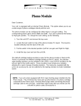
fully balanced design
Fully balanced circuitry is more than a tradition at Madrigal. The per-
formance advantages are as clear on the test bench as they are in the lis-
tening room. Logic dictated that we offer the best performance avail-

able from our balanced circuitry by including a balanced XLR input
connector version of the phono preamplifier modules.
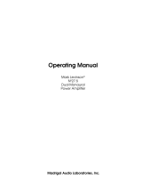
No32 XLR phono module
recommended wiring
LEFT +
LEFT -
TONE ARM GROUND
RIGHT +
RIGHT -
Combined with a shielded, twisted pair cable from cartridge to preamp,
the XLR input phono preamp offers the ultimate in noise rejection and
low level signal resolultion. (An RCA-equipped version is also available
for wider compatibility with existing phono cables.)
8
Madrigal uses a fully balanced implementation in its phono preampli-
fier. The gain stage produces a perfectly symmetrical pair of opposite-
polarity signals, based solely on the difference voltage appearing at the
amplifier input. Each half of the balanced signal sees identical signal
path and circuitry from input to output. The RIAA equalization stage
and even the DC servo is duplicated for each signal half. (A single resis-
tor change on the input amplifier would let each channel operate as a
stereo pair of phono preamplifiers.)
The balanced output signal from the phono preamp is received on the
Nº32 audio input selector board with the same treatment as a line level
balanced input.
instrumentation
amplifier topology
The classic method of resolving tiny electrical signals from potentially
noisy environments is called an “instrumentation amplifier.” The fully
balanced, input to output instrumentation amp—first pioneered in the
high end audio business in the Nº38 family of line-level preamplifi-
ers—is the ideal foundation on which to build a high performance
phono preamp.
The industry’s lowest noise amplifiers implement the input side of the
phono circuit. Gain is distributed over two stages with ample band-
NC
1
2
3
NC
1
2
3

width and open loop gain to provide uncompromised performance
even at the 60db of gain required by a moving coil preamplifier. The
instrumentation amplifier stage offers high common mode rejection, a
noise-cancellation feature usually limited to transformer-based designs,
while avoiding the serious limitations of those same designs.
high accuracy
RIAA equalization
A balanced pair of active RIAA equalization circuits follows the gain
stages. The filter is built with 0.1%, plate style (non-inductive), thin
film resistors and 1%, stacked film, polypropylene capacitors. This
yields less than 0.1db deviation from the ideal RIAA curve. The user
may switch an additional 20Hz high pass filter into the circuit. This fil-
ter effectively removes the subsonic noise common to many turntable
configurations. The filter conforms to the RIAA/IEC phono equaliza-
tion curve.
DC servo stabilized
Any potential for DC output from the phono preamp is nulled out by
an active DC servo. The servo is implemented with low noise, high per-
formance op-amps and film capacitors.
component selection
As with the rest of the components in the Nº32, the selection process
involved many hours of controlled listening tests above and beyond the
9
usual measurements and lab work. Some examples of the selections in-
clude:
•
Signal path resistors are 0.1% tolerance, non-inductive (plate-
style), thin-film parts.
•
Signal path capacitors are also non-inductive (stacked construc-
tion), either polypropylene or polyester in parallel polypropylene
film caps.
•
The preamp circuit board is four layer, Arlon™ N25 (an ultra
high speed, low loss material) construction.
•
Even non-signal path parts are film resistors and caps for best
long-term stability.
•
Low level signal interconnect is a flat conductor, Teflon™ insu-
lated balanced cable, soldered at both ends.
•
Low level signal relays are a rhodium contact, hermetically-
sealed reed type, optimized for ultra-low signal levels.
•
The entire module is fully enclosed in a conetic mu-metal shield
box for ultimate low frequency noise isolation.

Unpacking
Warning! Do not attempt to use your Nº32 Reference Phono
modules unless your Nº32 Controller is using version
1.3
(or greater) of its operating software. Prior to
installation, check your software by pressing Setup and
turning the Select knob one click to the left, and
reading the resulting display.
If you need new software, please contact your
authorized Mark Levinson dealer.
unpacking Unpack your Nº32 Reference Phono Preamplifier modules and keep all
packing materials for future transport. Locate and remove all accessory
items from the shipping carton. Accessories include:
1 wrist strap for ESD protection
1
5
⁄32" hex key
10
1
7
⁄64" hex driver
1
5
⁄64" hex driver
2
10-32 socket head cap screws
You will also need the
3
⁄
32
" hex driver that came with your Nº32 Refer-
ence Preamplifier in order to open the main Preamplifier unit.

Operating Voltage
The Nº32 Reference Preamplifier is set at the factory (internally) for
100V, 120V, 230V, 220V, or 240V AC mains operation @ 50 or 60Hz.
(230V/50Hz only in European Union countries, in compliance with CE
regulations.) This voltage setting cannot be changed by the user.
Make sure that the label near the AC receptacle of the Nº32 Controller
indicates the correct AC operating voltage for your location.
If the voltage indicated on your Nº32 Controller is incorrect, or if you
wish to change the AC operating voltage of your Nº32 as the result of
moving to a different country than the one in which you purchased
your preamplifier, see your Mark Levinson dealer.
The Nº32 is easily powered by a normal 15-ampere AC mains line. If
other devices are also powered from the same AC line, their additional
power consumption should be taken into account.
Caution!
It is extremely important that all components in your
system be properly grounded. Do not defeat a three-
11
prong AC cords with “ground-lifter” or “cheater”
adaptors, as doing so may allow dangerous voltages to
build up between components. The presence of these
voltages would pose a threat to both your person and
your equipment.
Warm up &
break-in period
Although your Mark Levinson Nº32 Reference Preamplifier delivers
outstanding performance straight out of the box, you should expect to
hear it continue to improve as it reaches its normal operating tempera-
tures and its various components “break-in.” It has been our experience
that the greatest changes occur within the first 25-50 hours, but that
the preamplifier will continue to improve in sound quality for about
300 hours, after which time it remains quite constant.
The only exception to this rule is if power is removed from the unit, al-
lowing it to cool down. In this case you should expect a brief warm-up
period before the preamplifier’s sound quality is at its best. (Fortu-
nately, you do not have to repeat the full 300-hour break-in period.)

Installing the Nº32 Reference
Phono Preamplifier Modules
Important!
Installation of the Nº32 Reference Phono Preampllifier
Modules should be done by a qualified and authorized
Mark Levinson dealer. The following description is
provided for your reference (and that of the dealer).
Failure to observe proper ESD (electrostatic discharge)
procedures may result in damage the preamplifier.
The optional Nº32 phono preamplifier modules may be installed inside
of the Nº32 preamplifier for seamless integration of a phonograph into
an audio system built around the Nº32. These modules are available
equipped either with XLR or the more common RCA connectors. The
following instructions apply to either version.
12
Warning! Do not attempt to use your Nº32 Reference Phono
modules unless your Nº32 Controller is using version
1.4
(or greater) of its operating software.
Prior to installation, check your software by pressing setup and turn-
ing the select knob one click to the left. Read the number on the right
side of the resulting display. It should be at least 1.04.
If you need new software, please contact your authorized Mark
Levinson dealer or distributor. Install this software before continuing
with the phono module installation.
Warning: Before continuing, turn off the Nº32 Controller, and
remove the DC power cables from the Nº32
Preamplifier. Once the Preamplifier top cover has been
removed, please use the supplied wrist strap between
you and the chassis of the Nº32 Preamplifier (not the
Controller) to prevent ESD damage.

material needed
The following materials and tools are needed to perform the installa-
tion of the Nº32 Phono modules into the Nº32 Preamplifier:
1 – Nº32 reference preamplifier
1 – pair Nº32 phono preamp modules
1 – wrist strap for ESD protection
1
–
3
⁄
32
" hex driver
1 –
5
⁄
64
" hex driver
1 –
5
⁄
32
" hex key
2
– 10-32 socket head cap screws
installation procedure
Carefully perform the following procedure after having read it through
at least once from start to finish; taking it one step at a time should
make it quite simple. Photographs are provided along the way for refer-
ence.
Note that if you intend to use the custom loading binding posts, you
will have to remove and reinstall the phono modules. If by chance you
know exactly what loading resistor you would like to use, you may
want to jump ahead to
Installing a Custom Load
, later in the manual,
and return to this section afterward. (Most people will find the stan-
dard assortment of loading options quite comprehensive.)
13
1.
Place the Nº32 reference preamp on suitable work area
Ideally, the work area itself should be grounded and static-free. It
should also be clear of small parts and other items that might get
in the way. Have a separate area prepared ahead of time for laying
out the disassembled parts during the procedure. (A soft towel
laid on a table works well to keep screws from rolling off onto the
floor.)
2.
Remove
DC
power cables from the Nº32 Preamplifier
There is no need to disconnect the Nº32 Controller from the AC
mains, although there is no real harm in doing so, either. either
way, however, you must disconnect the DC power cables between
the Controller and the Preamplifier, allowing the Preamplifier to
“float” with respect to ground.

3.
Remove
the
two
screws
fr
om
rear
bottom
of
Nº32
Preampli-
fier
top
cover
that
hold
it
in
place
(using
the
3
⁄
32
”
hex
key
supplied
with
the
Nº32).
These are located at the bottom outside corners of the rear panel.
14
4.
Slide top cover back slightly then up and off.
Once you have slid the cover back approximately one-half inch
(or about a centimeter), the cover can be lifted straight up and off.
Note that you must clear the “key” in the front center of the top
cover that fits into the front panel before you can lift the cover up.

5.
Peel off the protective film covering the copper strip on the
end of the wrist strap, and attach it so that the copper strip
contacts the chassis of the Nº32; wrap the other end
around your wrist.
Grounding yourself to the chassis on which you are working, us-
ing a conductive ESD wrist strap, ensures that no voltage can
build up between you and and part of the chassis. This is impor-
tant since the chassis includes some components that are sensitive
to electrostatic discharges (ESD). (
Had you connected this wrist
strap earlier, it could have gotten in the way when trying to remove
the top cover.
)
6.
Remove
the
four
bottom
screws
fr
om
phono
option
cover
plates
on
rear
of
Nº32
Pr
eamplifier
(
7
⁄
64
”
hex)
Save these screws in a safe place, as you will need them again once
the phono modules are in place.
15
(resulting in…)
7.
Make sure cables on top of phono preamp modules have
connector ends in holes in top cover.
The ribbon cables on the top of the phono modules should have
their ends tucked into the slots near the end of the module, as
shown below:

this
, not
Warning: The cables must lie flat against phono preamp top
cover to slide in to Nº32 preamp.
8.
Gently slide the left phono preamp module into the open-
ing in the left channel of the Nº32 preamp. Repeat for right
channel.
16
Do not force! The phono preamp modules should slide in easily.
If a phono preamp module does not slide in easily, remove it and
repeat step 7.
9.
Reinstall
the
four
screws
that
were
r
emoved
fr
om
phono
option
cover
plate
(
7
⁄
64
”
hex
key)
Please take care to avoid cross-threading these relatively small
screws.
10.
Install
two
10-32
socket
head
cap
screws
into
floor
of
Nº32
Pr
eamplifie
r
,
thr
ough
the
mounting
tabs
in
the
phono
preamp
modules.
(
5
⁄
32
”
hex
key)
These are the relatively heavy-duty screws that were supplied with
your Nº32 phono modules. The floor of the Nº32 has threaded
inserts waiting to accept these screws.

11.
Carefully lift connector ends of cables out of holes in phono
preamp top cover.
Being careful to avoid catching the connectors on the edges of the
slots in which they have been sitting during installation, set the
unattached ends of the ribbons cable free as shown below.
17
12.
Plug all four cables from phono preamp modules into their
respective sockets on upper circuit board inside Nº32
Preamplifier.
Note that the connector will “click” when fully seated.
(all four connections)

(closeup)
13.
Remove your ESD wrist strap from the chassi and from your
wrist.
It would hinder your replacing the top cover, next.
14.
Replace
Nº32
preamp
top
cover
and
screws
(
3
⁄
32
”
hex
key)
W
hen
replacing
the
t
o
p
c
o
v
er
,
not
e
the
guide
pins
at
the
bott
om
edges
as
well
as
the
t
o
p
“
k
ey”
y
ou
not
iced
befo
re
.
All
three
must
be
line
d
up
befo
re
y
ou
slide
the
t
o
p
cov
er
fo
rward,
fl
ush
w
ith
the
18
front panel.
15.
Reconnect the DC interface cables and restore power to the
Controller (if you powered it down earlier)
Congratulations! The new phono inputs will automatically ap-
pear as available input selections.

Customizing Your Nº32
setup overview
The Nº32 Preamplifier has many provisions for custom-tailoring the
system’s operation to match your preferences. The method for modify-
ing any of these settings is to:
•
press the setup button on either the front panel or the re-
mote control to enter the setup mode, accessing the Nº32’s
menu system;
•
navigate among different menu items using the select
knob or the remote control’s select buttons;
•
change the value of the selected menu item using either
the volume knob or volume +/– buttons on the remote.
•
move down a level within a menu, or save the change by
pressing enter on either the front panel or the remote con-
trol. (You can avoid saving an unwanted change by leaving
the menu without pressing enter, by pressing setup in-
stead.)
This four-step process gives you extensive control over a wide variety of
setup options, and provides positive feedback that your changes have
been accepted and saved for future use.
19
the menu system
The complete Nº32 Setup menu is shown below for your reference:
No32 Setup
Set Inputs
Set Input 1
Name=INPUT 1
Gain= +6 dB
Offset= 0.0
Rec.Out=NONE
Set Input 2 (repeats previous menu)
Set Input 3 (repeats previous menu)
Set Input 4 (repeats previous menu, with +12 dB gain)
Set Input 5 (repeats previous menu)
Set Input 6 (repeats previous menu)
Set Input 7 (repeats previous menu)
Set Input 8 (repeats previous menu)
(continued next page)

Set Phono 1
Name= PH/MC 1
Ph Gain= +60
Gain= +12 dB
Offset= 0.0
Bal= <-0.0->
20Hz HPF=ON
R Load=100 C
Load=.01uF
Set Phono 2
Name= PH/MM 2
Ph Gain= +40
Gain= +12 dB
Offset= 0.0
Bal= <-0.0->
20Hz HPF=ON
R Load=47k C
Load=100pF
Teach IR
Mute = -20.0
MaxVol= 80.0
Trig.= 12v,L
Sw 1.07 1.02
(the software version numbers
)
20
The Nº32’s extensive menu system allows you to customize the way the
preamplifier operates, to better suit the needs of your system and your
personal preferences. We will review the following information in more
detail in the coming pages, on an item-by-item basis.
(Don’t worry, it
isn’t really as complicated as it seems when you take it one step at a time.)
configuring
phono inputs
Configuring your phono inputs is quite similar to configuring line level
inputs, with the exception that there are several more items that may be
set, including the “Ph Gain” of the phono preamplifier (as distinct from
the Gain of the line level preamplifier), the phono loading, and even a
balance offset that is unique to each phono input, to compensate for
the small errors common in phono cartridges. Each phono input may
be customized in the following ways:
•
Name— the name of the input shown in the front panel’s
display when the input is selected.
•
Phono Gain— the amount of gain provided for within
the phono preamplifier module itself, generally 40 dB for
moving magnet cartridges and 60 dB for moving coils.
•
(Line) Gain—
the amount of gain used in the line-level
portion of the preamplifier for that particular input, 0 dB
(attenuation only), +6 dB, +12 dB, or +18 dB; set after the
phono gain is established, and used to optimize the match
/