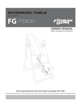
OWNER’S MANUAL
Triple SureLock
®
Inversion Table
4513.1-121819


1
TABLE OF CONTENTS
SERVICE-----------------------------------------------------------
2
IMPORTANT SAFETY GUIDELINES------------------------
3
LABEL PLACEMENT--------------------------------------------
6
OVERVIEW DRAWING-----------------------------------------
7
HARDWARE & TOOLS PACK---------------------------------
8
PARTS LIST--------------------------------------------------------
9
ASSEMBLY---------------------------------------------------------
10
OPERATION AND ADJUSTMENTS-------------------------
20
STORAGE----------------------------------------------------------
28
WARRANTY--------------------------------------------------------
29
PARTS REQUEST FORM--------------------------------------
30

2
SERVICE
IMPORTANT: FOR NORTH AMERICA ONLY
For damaged or defective product, questions, replacement parts or any other service support, please
contact our customer service department by the below methods:
For The Best Service, please Email:
service@paradigmhw.com
Response Time: 1-2 Business Days
Emailing us with the information above will be the best method to receive a response during peak business
hours
Website:
www.paradigmhw.com
Toll-Free:
1-844-641-7921
(8:00 AM - 5:00 PM Pacific Standard Time, Monday thru Friday)
Response time may vary via calling
Please have the following information ready when requesting for service:
Your name
Phone number
Model number
Serial number
Part number
Proof of Purchase
For damaged or defective product please contact our customer service before returning to the store.
Paradigm Health & Wellness, Inc.
1189 Jellick Ave.
City of Industry, CA 91748, USA

3
IMPORTANT SAFETY GUIDELINES
Always check to make sure the ankle locking pin is fully
engaged before each use. Make sure that the front and rear
ankle clamps are secured tightly against your ankles to
prevent from falling when the table inverts.
WARNING: Failure to fully engage the locking pin could
result in serious injury or possible death.

4
IMPORTANT SAFETY GUIDELINES
Read all instructions before using the Inversion Table. When using an Inversion table, basic
precautions should always be followed, including the following
WARNING - To reduce the risk of injury to persons:
1. Make sure your equipment is correctly assembled before you use it.
2. Be sure all screws, nuts, and bolts are tightened prior to use.
3. Only one person should use the equipment at a time.
4. Never operate this equipment if it is damaged, If it is not working properly, has been dropped, or
damaged. If a problem is encountered contact Customer Service before using the equipment again.
5. Always use this equipment on a clear and level surface.
6. For Household Use Only.
7. Do not use outdoors or near water.
8. Do not use aggressive movements, or use weights, elastic bands, any other exercise or stretching
device. Use the inversion table only for its intended use as described in this manual. Do not use
attachments not recommended by the manufacturer.
9. Do not wear loose clothing when using the equipment.
10. Keep all hands and feet away from any moving parts.
11. Never drop or insert any object into any opening.
12. Always wear securely tied lace-up shoes with a flat sole, such as a normal tennis-style shoe.
13. Do not wear any footwear that could interfere with securing the ankle lock, such as shoes with thick
soles, boots, high-tops or any shoe that extends above the anklebone.
14. Close supervision is necessary when the inversion table is used near children, or by or near invalids
or disabled persons.
15. Do not operate equipment while under the influence of drugs, alcohol, or medication that may cause
drowsiness or disorientation.
16. Listen to your body. It is recommended that you rotate up and down slowly. Dizziness might occur if
you come up too fast.
17. If at any time you feel faint, light-headed, or dizziness while operating the equipment, stop exercising
immediately. You should also stop exercising if you are experiencing pain or any discomfort.
18. This appliance is not intended for use by persons with reduced physical, sensory or mental
capabilities, or lack of experience and knowledge, unless they have been given supervision
or instruction concerning use of the appliance by a person responsible for their safety. Keep
children under the age of 13 away from this machine.”
19. Always be certain the ankle lock is properly adjusted and fully engaged and that your ankles are
secure before using the equipment. HEAR, FEEL, SEE and TEST that the Ankle Lock is snug,
close-fitting and secure EVERY TIME you use the equipment.
20. Wait 2 hours after eating before using the inversion table. If you start feeling nauseous, return to the
upright position slowly.
21. For any problems contact customer service. Servicing should be performed by an authorized service
representative. Our contact number is on the service page.
22. WARNING: - Risk of Personal Injury - Consult with your personal physician to see if
inversion equipment is appropriate for you. This is especially important for people with pre-existing health
problems. Do not use this equipment without your physician's approval.
23. WARNING: - Risk of Personal Injury – Do not allow children to use this machine.

5
IMPORTANT SAFETY GUIDELINES
The product weighs more than 44 lbs. It is heavily
recommended that at least 2 persons assemble.
24. WARNING:- Risk of Personal Injury - Keep children under the age of 13 away from the
machine while in use.
25. WARNING:- Risk of Personal Injury – Keep body parts, hair, loose clothing, and jewelry
clear of all moving parts.
26. WARNING: - Risk of Personal Injury - Tilt-back slowly when inverting. Failure to comply
could result in serious bodily injury.
27. WARNING:- Risk of Personal Injury - Do not attempt to service the unit yourself. Discontinue
use and contact customer service.
28. WARNING: - To Reduce The Risk Of Personal Injury - Read And Understand All The
Instructions Before Using The Inversion Table.
Do not use this equipment if you have any of the following conditions or ailments:
Pregnancy
Extreme obesity
Middle ear infection
Hiatus hernia or Ventral hernia
Glaucoma, retinal detachment or conjunctivitis
Use of anticoagulants including Aspirin in high doses.
Spinal injury, Cerebral Sclerosis, or acutely swollen joints
Heart or circulatory disorders for which you are being treated
High blood pressure, Hypertension, Recent stroke or Transient Ischemic attack
Bone weaknesses including Osteoporosis, Unhealed fractures, Modular pins, or surgically
implanted orthopedic supports.
Do not exceed the maximum rated weight (load) and maximum
rated user height:
The Maximum Weight Capacity for this product is 300lbs / 136kgs.
The Maximum Height Capacity for this product is 6 feet 6 inches / 198cm.
Retain this owner’s manual and keep the original purchase receipt
for future reference.
SAVE THESE GUIDELINES
It is your responsibility to familiarize yourself with the proper use of this
equipment and the inherent risks of inversion if these instructions are not
followed, such as falling on your head or neck, pinching, entrapment,
equipment failure, or aggravating a pre-existing medical condition. It is
the responsibility of the owner to ensure that all users of the product are
fully informed about the proper use of the equipment and all safety
precautions.

6
LABEL PLACEMENTS
This drawing indicates the locations of the warning
labels found on your product. If a label is mi
ssing,
illegible or is removed, contact Customer Service to
request a complimentary replacement label.

7
OVERVIEW DRAWING

8
HARDWARE & TOOLS PACK

9
PARTS LIST
No.
Description
Qty
No.
Description
Qty
1
Foot Bar
2
33
Rubber Heal Holder
4
2
Right Front Post
1
34
Square Bushing
1
3
Left Front Post
1
35
Rod Cap
4
4
Front Support Post
1
36
Oval End Cap
2
5
Metal Plate
2
37
Handlebar
4
6
Right Rear Post
1
38
Foam Grip
4
7
Left Rear Post
1
39
Round End Cap
2
8
Plastic Spacer
4
40
Hex Bolt M4*8
3
9
Pivot Arm
2
41
Plastic Round End Cap
2
10
Backrest Frame
1
42
Foot Cap
4
11
Adjustable Boom Knob
1
43
Rubber Pad
2
12
Backrest
1
44
Short Nylon Strap
1
13
Headrest
1
45
Long Nylon Strap
1
14
Heating Lumbar Pad
1
46
Socket Hex Bolt M8*65
4
15
Adjustable Boom
1
47
Hex Bolt M8*55
8
16
Adjustable Instep Frame
1
48
Hex Bolt M8*60
2
17
Lock Release
1
49
Ring Pin
1
18
Foot Bar
1
50
Hex Bolt M8*20
2
19
Rear Ankle Rod
1
51
Hex Bolt M8*23
4
20
Metal Bushing
1
52
Phillips Screw M6*12
6
21
Front Ankle Rod
1
53
Phillips Screw M6*50
2
22
Locking Pin
1
54
Carriage Bolt M8*43
2
23
Spring
1
55
Hex Bolt M8*40
1
24
Pin Shaft Cap
1
56
Hex Bolt M8*50
1
25
Pin Shaft
1
57
Hex Bolt M6*40
1
26
Locking Indicator
1
58
Flat Washer Φ12*Φ6.5*1.5
9
27
Locking Pin Knob
1
59
Flat Washer Φ16*Φ8.5*1.5
18
28
Hex Bolt
1
60
Nylon Nut M6
1
29
Instep Retracting Spring
1
61
Nylon Nut M8
18
30
Self-Locked Spring
1
62
Eva Pad
2
31
Spring Pin
1
63
Bolt M6*6
1
32
Steel Heel Holder Bracket
4
64
Power Cord
1

10
ASSEMBLY
Step 1
Note: The parts are labeled with R and L decals to indicate the left and right sides. The left and
right side are labeled as if you are on the inversion table.
1A. Connecting the Front & Rear Posts:
Attach the Left & Right Front Post (3) & (2) onto the Left & Right Rear Post (7) & (6) with two
Hex Bolts (48), two Flat Washers (59), and two Nylon Nuts (61). Simultaneously tighten the
hardware with the two 13, 17mm Wrenches provided.
(59) Flat Washers
2 PCS
(61) Nylon Nut
2 PCS
(48) Hex Bolt
2 PCS
Tools:
13, 17mm Wrench
2PCS
Hardware:
Facing
each other

11
ASSEMBLY
Step 2
2A. Installing the Foot Bar:
Make sure the indented holes on the Foot Bar (1) are facing downward. See Fig. A. Attach a
Foot Bar (1) onto both Left & Right Rear Post (7) & (6) with two Socket Hex Bolts (46). Attach
the second Foot Bar (1) to the Left & Right Font Post (3) & (2) with two Socket Hex Bolts (46).
DO NOT fully tighten the hardware until instructed to do so in STEP 3.
DO NOT fully tighten Socket Hex Bolts (46) at this time.
2B. Locking the Front & Rear Posts:
Then insert the Ring Pin (49) into the hole on the right side of the frame to lock the Right Front
Post (2) & Right Rear Post (6) in the open position.
(46) Socket Hex Bolt
4 PCS
Hardware:
Fig. A
Facing
each other
(49) Ring Pin
1 PC

12
ASSEMBLY
Step 3
Note: The parts are labeled with R and L decals to indicate the left and right sides. The left and
right side are labeled as if you are on the inversion table.
3A. Installing the Front Support Post
Align the Front Support Post (4) and two Metal Plates (5) with both the Left & Right Front
Posts (3) & (2). Attach with four Hex Bolts (47), four Flat Washers (59), and four Nylon Nuts
(61). DO NOT fully tighten the hardware until instructed to do so in STEP 4.
DO NOT fully tighten Socket Hex Bolts (47) at this time.
3B. NOW fully tighten the four Socket Hex Bolts (46) using the 6mm Allen Wrench provided.
3C. Attach two Rubber Pads (43) onto the Front Support Post (4).
3D. install a Foot Caps (41) onto each end of the Foot Bars (1).
(59) Flat Washers
4 PCS
(61) Nylon Nut
4 PCS
Hardware:
(47) Hex Bolt
4 PCS
Tools:
13,17mm Wrench
2PCS
6mm Allen Wrench
1PC

13
ASSEMBLY
Step 4
Note: We recommend two people work together to install the Backrest Frame (10).
Note: The Hex Bolts (51) should be installed from the inside as shown in the illustration
above.
4A. Installing the Backrest:
Slide the brackets of the Backrest Frame (10) onto the left and right Pivot Arms (9).
Aligning the holes of the the Pivot Arms (9) with the brackets of the Backrest Frame (10).
Secure with two Hex Bolts (51), two Flat Washers (59), and two Nylon Nuts (61). Tighten
the hardware with the two 13, 17mm Wrenches provided.
4B. NOW fully tighten the four Socket Hex Bolts (47) using the two 13, 17mm Wrenches
provided.
Note: Fig. B shows a correctly installed Pivot Arm (9) and Backrest Frame (10).
Hardware:
(51) Hex Bolt
4PCS
(59) Flat Washer
4PCS
(61) Nylon Nut
4PCS
Fig. B
Tools:
13,17mm Wrench
2PCS
These parts must be
on same side when
installing the backrest.

14
ASSEMBLY
Step 5
Installing the Handle Bars:
5A. Attach the Handlebars (37) onto the Right and Left Rear Post (6 & 7) with two Hex Bolts
(47), two Flat Washers (59), and two Nylon Nuts (61). Tighten the hardware with the two 13,
17mm Wrenches provided.
(59) Flat Washers
4 PCS
(61) Nylon Nut
4 PCS
(47) Hex Bolt
4 PCS
Hardware:
Tools:
13,17mm Wrench
2PCS

15
ASSEMBLY
Step 6
6A. Installing the Foot Bar:
Align and secure the Foot Bar (18) into the bottom of the Lock Release (17) with two Carriage
Bolts (54), two Flat Washers (59), and two Nylon Nuts (61). Tighten the hardware with the 13,
17mm Wrench provided.
(61) Nylon Nut
2PCS
(54) Carriage Bolt
2PCS
(59) Flat Washer
2PCS
Hardware:
Tool:
13,17mm Wrench
1 PCS

16
ASSEMBLY
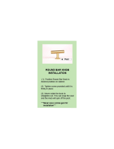
Step 7
7A. Installing the Rod for the Heel Holders:
With both slots facing the Adjustable Instep Frame Knob (27), slide the Rear Ankle Rod (19)
through the large round hole on the side of the Adjustable Boom (15). Secure the Rear Rod (19)
on the Adjustable Boom (15) with one Hex Bolt (56), one Metal Bushing (20), one Nylon Nut
(61), one Flat Washer (59). Simultaneously tighten the bolt and nut with the 13, 17mm
Wrenches provided.
7B. Installing the Rubber Heel Holders:
Wrap each Rubber Heel Holder (33) with one Steel Heel Holder Bracket (32). Squeeze and
slide one set of the Rubber Heel Holder (33) and Steel Heel Holder Bracket (32) onto the each
end of the Rear Ankle Rod (19).
NOTE: Fig. C & D
Make sure the lock teeth of the Steel Heel Holder Brackets (32) are wedged into the slots in the
Rear Ankle Rod (19) to lock the Rubber Heel Holders (33) in place before use.
(56) Hex Bolt
1PC
(61) Nylon Nut
1PC
(59) Flat Washer
1PC
(20) Metal Bushing
1PC
Tool:
13,17mm Wrench
2 PCS
Hardware:
C
D

17
Step 8
8A. Installing the Front Rod
With both the slots facing the Adjustable Instep Frame Knob (27), slide the Front Ankle Rod
(21) through the Adjustable Instep Frame (16). Secure the Front Ankle Rod (21) to the
Adjustable Instep Frame (16) with two Hex Bolts (40). Tighten the hardware with the 3mm
Allen Wrench provided.
8B. Installing the Rubber Heel Holders:
Wrap each Rubber Heel Holder (33) with one Steel Heel Holder Bracket (32). Squeeze and
slide one set of the Rubber Heel Holder (33) and Steel Heel Holder Bracket (32) onto the each
end of the Front Ankle Rod (21).
NOTE: Fig. C & D
Make sure the lock teeth of the Steel Heel Holder Brackets (32) are wedged into the slots in the
Front Ankle Rod (21) to lock the Rubber Heel Holders (33) in place before use.
ASSEMBLY
C
D
3mm Allen Wrench
1PC
Tool:
(40) Hex Bolt
2PCS
Hardware:

18
Step 9
9A. Installing the Adjustable Boom to the Backrest Frame:
Pull out and hold the Adjustable Boom Knob (11), and slide the Adjustable Boom (15) into the
bottom of the Backrest Frame (10). Slide the Adjustable Boom (15) upwards until the desired
height is visible below the Backrest Frame (10). To lock the Adjustable Boom (15) in place
release the Adjustable Boom Knob (11). Shift the Adjustable Boom (15) inwards until the
Adjustable Boom Knob (11) "POPS" down into the locked position. Make sure the Adjustable
Boom Knob (11) is fully inserted. See Fig. E.
Step 10
10A. Attaching the Nylon Straps
Attach the combined Long Nylon Strap (45) & Short Loop Strap (44) to the Backrest Frame
(10). This is done by hooking one end of the Safety Hooks on the Long Nylon Strap (45) to the
triangular tab on the underside of the Backrest Frame (10). Then hook the other end of the
Safety Hooks on the Short Nylon Strap (44) to the triangular tab on the Front Support Post
(4).
ASSEMBLY
Fig. E
11
11
4
Page is loading ...
Page is loading ...
Page is loading ...
Page is loading ...
Page is loading ...
Page is loading ...
Page is loading ...
Page is loading ...
Page is loading ...
Page is loading ...
Page is loading ...
Page is loading ...
/