Page is loading ...

OWNER’S MANUAL
1318Y.2-082818
ELLIPTICAL
IMPORTANT: Read all instructions carefully before using this product. Retain this
owner’s manual for future reference. The specifications of this product may vary from
this photo and, subject to change without notice.


1
TABLE OF CONTENTS
SERVICE ------------------------------------------------------------------------------------ 2
LABEL PLACEMENT --------------------------------------------------------------------- 3
IMPORTANT SAFETY GUIDELINES ------------------------------------------------ 4
OVERVIEW DRAWING ------------------------------------------------------------------ 6
PARTS LIST -------------------------------------------------------------------------------- 8
HARDWARE & TOOLS PACK -------------------------------------------------------- 10
ASSEMBLY --------------------------------------------------------------------------------- 11
CONSOLE---------------------------------------------------------------------------------- 25
ADJUSTMENTS--------------------------------------------------------------------------- 32
TROUBLESHOOTING & MAINTENANCE ----------------------------------------- 33
WARRANTY ------------------------------------------------------------------------------- 34
PARTS REQUEST FORM ------------------------------------------------------------- 35

2
SERVICE
IMPORTANT: FOR NORTH AMERICA ONLY
For damaged or defective product, questions, replacement parts or any other service
support, please contact our customer service department by the below methods:
For The Best Service, please Email:
service@paradigmhw.com
Response Time: 1-2 Business Days
Emailing us with the information above will be the best method to receive a response during
peak business hours
Website:
www.paradigmhw.com
Toll-Free:
1-844-641-7921
(8:00 AM - 5:00 PM Pacific Standard Time, Monday thru Friday)
Response time may vary via calling
Please have the following information ready when requesting for service:
Your name
Phone number
Model number
Serial number
Part number
Proof of Purchase
For damaged or defective product please contact our customer service before returning to
the store.
Paradigm Health & Wellness, Inc.
1189 Jellick Ave.
City of Industry, CA 91748, USA

3
LABEL PLACEMENT

4
IMPORTANT SAFETY GUIDELINES
Read all guidelines before using this machine. When using this machine,
basic precautions should always be followed, including the following:
WARNING - To reduce the risk of injury to persons:
1. Make sure your equipment is correctly assembled before you use it.
2. Be sure all screws, nuts, and bolts are tightened prior to use.
3. Before using this equipment, we recommend doing warm ups.
4. Only one person should be using the equipment at a time.
5. Never operate this Equipment if it is damaged, if it is not working properly, has been dropped, or
damaged. If a problem is encountered contact Customer Service before using the equipment
again.
6. Always use this equipment on a clear and level surface.
7. For household use only.
8. Do not use outdoors or near water.
9. Use the machine only for its intended use as described in this manual. Do not use attachments
not recommended by the manufacturer.
10. Do not wear loose clothing when using the equipment.
11. Never drop or insert any object into any opening.
12. If at any time you feel faint, light-headed, or dizziness while operating the equipment, stop
exercising immediately. You should also stop exercising if you are experiencing pain or any
discomfort.
13. For any problems contact customer service. Servicing should be performed by an authorized
service representative. Our contact number is on the service page.
14. This product requires a minimum of 6 square feet of space for safe operation.
15. Be careful to always hold onto the handlebars when you’re mounting and dismounting.
16. Be careful to have the pedals at their lowest point when stepping off.
17. Hold onto the handlebars and use both the pedals in tandem to ensure a smooth, effective
workout.
18. Warning: - Risk of Personal Injury - Consult with your personal physician to see if exercise
equipment is appropriate for you. This is especially important for people with pre-existing health
problems. Do not use this equipment without your physician's approval.
19. Warning: - Risk of Personal Injury – Do not allow children to use this machine.
20. Warning: - Risk of Personal Injury - Keep children under the age of 13 away from the
machine.
21. Warning: - Risk of Personal Injury – Keep body parts, hair, loose clothing, and jewelry
clear of all moving parts.
22. Warning: - Risk of Personal Injury - Do not attempt to service the unit yourself.
Discontinue use and contact customer service.
23. Warning: - To Reduce The Risk Of Personal Injury - Read And Understand All Read The
Instructions Before Using This Machine
24. WARNING: CANCER AND REPRODUCTIVE
HARM--WWW.P65WARNINGS.CA.GOV

5
The product weighs more than 44 lbs. It is heavily
recommended that at least 2 persons assemble.
IMPORTANT SAFETY GUIDELINES
Do not use this equipment if you have any of the following conditions or ailments:
Pregnancy
Extreme obesity
Middle ear infection
Hiatus hernia or Ventral hernia
Glaucoma, retinal detachment or conjunctivitis
Use of anticoagulants including Aspirin in high doses.
Spinal injury, Cerebral Sclerosis, or acutely swollen joints
Heart or circulatory disorders for which you are being treated
High blood pressure, Hypertension, Recent stroke or Transient Ischemic attack
Bone weaknesses including Osteoporosis, Unhealed fractures, Modular pins, or surgically
implanted orthopedic supports.
DO NOT EXCEED THE MAXIMUM RATED WEIGHT CAPACITY
The Maximum Weight Capacity for this product is 270 lbs/123 kgs.
RETAIN THIS OWNER’S MANUAL AND KEEP THE
ORIGINAL PURCHASE RECEIPT FOR FUTURE
REFERENCE.
&
SAVE THESE GUIDELINES
!

6
OVERVIEW DRAWING

7
OVERVIEW DRAWING

8
PARTS LIST
No.
Description
Qty
No.
Description
Qty
1
Main Frame
1
36
Right Foot Bar Cover Ⅰ
1
2
Front Post
1
37
Right Foot Bar Cover Ⅱ
1
3
Handrail Arm
2
38
Hex Bolt M12*80
2
4
Left Handrail
1
39
Flat Washer φ24*φ12.5*2
2
5
Right Handrail
1
40
Anti-Loose Hex Nut M12
2
6
Left Foot Bar
1
41
Left Pedal
1
7
Right Foot Bar
1
42
Right Pedal
1
8
Front Stabilizer Ф60*1.5*480
1
43
Carraige Bolt M6*45
4
9
Rear Stabilizer Ф60*1.5*580
1
44
Flat Washer φ6*φ12*1.0
8
10
Handlebar Post
1
45
Anti-Loose Hex Nut M6
4
11
Handlebar End Cap
2
46
Powder Metal Bushing φ18*φ8*10
4
12
Foam Grip φ27*φ33*360
2
47
Flat Hex Bolt S6 M8*20
2
13
Hand Pulse Sensor
2
48
Big Flat Washer φ8*φ25*2.0
2
14
Self-Tapping Phillips Screw ST4.2*20
25
49
D Washer φ28*2
2
15
Console
1
50
Wave Washer φ28*φ17*0.3
2
16
Hex Bolt M5*10
4
51
Powder Metal Bushing Ф24.5*Ф16*14
4
17
Console Wire L=1100
1
52
Hex Bolt M8*50
2
18
Handrail End Cap
2
53
Flat Washer Ф8*Ф16*1.5
3
19
Foam Grip φ31*φ37*830
2
54
Left U Shape Bracket Cover Ⅰ
1
20
Hex Bolt S6 M8*20
12
55
Left U Shape Bracket Cover Ⅱ
1
21
Spring Washer φ8
18
56
Right U Shape Bracket Cover Ⅰ
1
22
Big Curved Washer φ20*φ8*2
14
57
Right U Shape Bracket Cover Ⅱ
1
23
Front Post Cover
2
58
U Shape Bracket
2
24
Dished Washer φ8*φ33*2.0
2
59
Crank Cover Ⅰ
2
25
D-Washer φ38*3
2
60
Crank Cover Ⅱ
4
26
Wave Washer Φ19*Φ23*0.3
2
61
Carriage Bolt M8*75
4
27
Metal Bushing φ38,φ32,φ19,14
4
62
Cap Nut M8
4
28
Bushing φ38*60
2
63
Rear Stabilizer End Cap
2
29
Hex Bolt M8*45
4
64
Front Stabilizer End Cap
2
30
Curved Washer φ8*φ16*1.5
4
65
Self-Drilling Phillips Screw ST4.2*20
13
31
Anti-Loose Hex Nut M8
7
66
Lower Conosle Wire
1
32
Metal Bushing φ32*φ16.2*15
4
67
Power Jack
1
33
Spacer φ16*1.5*59.7
2
68
Adaptor
1
34
Left Foot Bar Cover Ⅰ
1
69
Crank
2
35
Left Foot Bar Cover Ⅱ
1
70
Bottle Holder
1

9
HARDWARE & TOOLS PACK
PARTS LIST
No.
Description
Qty
No.
Description
Qty
71
Self-Tapping Phillips Screw ST4.8*15
2
94
Eye Bolt M6*36
5
72
Flange Nut M10*1.25*6
2
95
U-Bracket 31*30*δ1.0
4
73
Crank Cover Ⅲ
2
96
Hex Nut M6
5
74
Shroud Plug φ82*φ42*8
2
97
Axle Ring Φ12*1.0
4
75
Left Protective Cover
1
98
Belt Pulley Shaft Φ12*94-M10*1
1
76
Right Protective Cover
1
99
Bearing 6001
4
77
C-Ring Φ17*1.0
2
100
Belt Pulley
1
78
Wave Washer Φ20*Φ24*0.3
1
101
Belt 330 PJ3
1
79
Bearing 6004-2Z
2
102
Fly Wheel Φ180
1
80
Inductor
1
103
Flywheel Shaft
1
81
Self-Tapping Phillips Screw ST2.9*12
2
104
Bolt M6*60
1
82
Belt Pulley Φ200
1
105
Spring φ8*φ1*50
1
83
Anti-Loose Hex Nut M6
10
106
Magenet Bracket
1
84
Spring Washer Ф6
12
107
Sqaure Magnet 30*20*12
9
85
Cross Pan Head Bolt M6*15
12
108
Sleeve φ18*φ8*10
2
86
Belt
1
109
Hex Bolt M8*55;L20
1
87
Hex Bolt M8*35
1
110
Self-Tappig Phillips Screw ST4.8*20
2
88
Hex Nut M8
1
111
Bracket Supporter
1
89
Idle Wheel Fixture
1
112
Motor
1
90
Idle Wheel
1
113
Tension Cable
1
91
Anti Loose Nut M8
1
114
Flat Hex Nut S15
1
92
Hex Bolt M8*10
1
115
Front Hand Post Cover
2
93
Flange Nut M10*1.0*6
4
116
Rera Hand Post Cover
2

10
HARDWARE & TOOLS PACK

11
ASSEMBLY
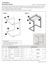
Step 1
1a. Remove the Metal Tubes A & B from the Main Frame (1) by using 6mm Allen Wrench
provided.
1b. Discard the Metal Tubes A & B and the associated hardware at that was removed. These parts
are not needed for the assembly of the elliptical.
6 mm Allen Wrench
Tool:

12
ASSEMBLY
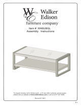
STEP 2
2a. Installing the Front Stabilizer –Lift up the front of the Main Frame (1), and then align the
holes of the Front Stabilizer (8) with the holes on the front curve of the Main Frame (1). Insert two
Carriage Bolts (61) and attach two Big Curved Washers (22), two Spring Washers (21), and two
Cap Nuts (62) to the threaded side of the two Carriage Bolts (61). Use the Multi Hex Tool with
Phillips Screwdriver to tighten the Cap Nuts (62) until firm and secure.
Note: The wheels on the Front Stabilizer (8) should not be touching the floor when installed, the
wheels should only touch the ground when the unit is tilted forward for transporting. See the UP
sticker on the stabilizer.
2b. Repeat the same process for installing the Rear Stabilizer (9).
HARDWARE PACK
(61) Carriage Bolt
4 PCS
(22) Big Curved
Washer
4 PCS
(62) Cap Nut M8
4 PCS
(21) Spring Washer
4 PCS
Tool:
Multi Hex Tool with Phillips
Screwdriver

13
ASSEMBLY
STEP 3
3a. Removing The Hardware From The Front Post –Use the 6mm Allen Wrench to remove the
eight Hex Bolts (20), eight Spring Washers (21), and eight Big Curved Washers (22) from the
Front Post (2).
3b. Connecting The Console Wires –Connect the Console Wire (17) from the Front Post (2) to
the Lower Console Wire (66) coming out from the Main Frame (1) as shown in Figure A.
3c. Installing The Front Post –Guide the wires into the Main Frame (1) as you insert the Front
Post (2) into the Main Frame (1); make sure the wires are not pinched and stay connected. Place
the Front Post (2) onto the Main Frame (1). Reinstall the previously removed hardware: eight Hex
Bolts (20), eight Spring Washers (21), and eight Big Curved Washers (22) and securely tighten
the bolts in sequence using the 6mm Allen Wrench provided.
6 mm Allen Wrench
Tool:
MUST TIGHTEN
IN SEQUENCE:
A,B,C,D,E,F,G,H.
!

14
ASSEMBLY
STEP 4
Note: The parts are marked with an “R” for right side and “L” for left side.
4a. Removing The Hardware From The Front Post –Use the 6mm Allen Wrench to remove the
two D Washers (25), two Dished Washers (24), two Spring Washers (21) and two Hex Bolts (20)
from the Front Post (2).
4b. Installing the Left Handrail – Keep the Bushing (28) and Wave Washer (26) in place
and slide the Left Handrail (4) onto the left side of the Front Post (2). Insert one D Washer
(25), one Dished Washer (24), one Spring Washer (21) and one Hex Bolt (20) that were
previously removed. Tighten the hardware by using the 6mm Allen Wrench until firm and
secure.
NOTE: The D Washer (25) should be installed as shown in Fig. B so it fits with the D shaped
shaft on the Front Post (2).
NOTE: The Dished Washer (24) should be installed as showing in Fig. C with the open side of
the dish facing away from the Front Post (2).
4c. Installing the Right Handrail – Repeat the same assembly steps for installing the Right
Handrail (5) onto the Front Post (2).
6 mm Allen Wrench
Tool:
24
Fig. C
Fig. B

15
ASSEMBLY
STEP 5
5a. Removing Hardware-Remove the two Flat Hex Bolts (47), two Spring Washers (21), two
Big Flat Washers (48), two Wave Washers (50), and two D Washers (49) from the both Cranks
(69). Keep this hardware for steps 6 & 7.
5b. Installing the Crank Covers Ⅰ and Ⅱ (59) & (60)-Slide one Crank Cover Ⅰ(59)
all the way down the shaft of the Left side of Crank (69). Hold one Crank Cover Ⅱ(60)
onto the backside of the Left side of Crank (69). Attach the Crank CoverⅠ (59) to the Crank
Cover Ⅱ(60) with two Self-Tapping Phillips Screws (14). Tighten the screws with the Multi Hex
Tool with Phillips Screwdriver provided.
5c. Repeat the same assembly step for installing the second set of Crank Covers Ⅰ and Ⅱ
(59) & (60) on to the the right side Crank (69).
HARDWARE PACK
(14) Self-Tapping
Phillips Screws
4 PCS
Tool:
Multi Hex Tool with Phillips
Screwdriver

16
ASSEMBLY
STEP 6
Note: The parts are marked with an “R” for right side and “L” for left side.
6a. Installing the Left Foot Bar – Slide one Wave Washer (50) followed by the U Shape Bracket
(58) on to the shaft of the left side Crank (69). Insert one D Washer (49), one Big Flat Washer (48),
one Spring Washer (21) and one Flat Hex Bolt (47) that were previously removed from STEP 5.
Tighten the hardware by using the 6mm Allen Wrench until firm and secure.
NOTE: The D Washer (48) should be installed as shown in Fig. D so it fits with the D shaped
shaft on the Crank (69).
6b. Installing the Left Handrail Arm – Insert the left Handrail Arm (3) into the Left Handrail (4).
Insert two Hex Bolts (29), two Curved Washers (30), and two Anti-Loosen Hex Nut (31). Tighten
the hardware with the 6mm Allen Wrench provided.
6 mm Allen Wrench
Tool:
HARDWARE PACK
(30) Curved Washer
2PCS
(31) Anti-Loosen
Hex Nut 2PCS
(29) Hex Bolt
2PCS
Fig. D

17
ASSEMBLY
STEP 7
Note: The parts are marked with an “R” for right side and “L” for left side.
7a. Installing the Right Foot Bar – Slide one Wave Washer (50) followed by the U Shape
Bracket (58) on to the shaft of the right side Crank (69). Insert one D Washer (49), one Big Flat
Washer (48), one Spring Washer (21) and one Flat Hex Bolt (47) that were previously removed
from STEP 5. Tighten the hardware by using the 6mm Allen Wrench until firm and secure.
NOTE: The D Washer (48) should be installed as shown in Fig. E so it fits with the D shaped
shaft on the Crank (69).
7b. Installing the Right Handrail Arm – Insert the left Handrail Arm (3) into the Right Handrail
(5). Insert two Hex Bolts (29), two Curved Washers (30), and two Anti-Loosen Hex Nut (31).
Tighten the hardware with the 6mm Allen Wrench provided.
(29) Hex Bolt
2PCS
(30) Curved Washer
2PCS
(31) Anti-Loosen Hex
Nut 2PCS
HARDWARE PACK
6 mm Allen Wrench
Tool:
Fig. E

18
ASSEMBLY
STEP 8
Note: The parts are marked with an “R” for right side and “L” for left side.
8a. Installing The Left Pedal – Install the Left Pedal (41) onto the Left Foot Bar (6) and align the
holes. Insert two Carriage Bolts (43) into the Left Pedal (41). Attach two Flat Washers (44), and
two Anti-Loosen Hex Nuts (45) to the threaded side of the two Carriage Bolts (43). Tighten the
hardware with the Multi Hex Tool with Phillips Screwdriver.
8b. Installing The Right Foot Pedal: Repeat the same assembly steps to install the Right Foot
Pedal (42) onto the Right Foot Bar (7).
NOTE: There are four holes on the Left/Right Foot Bars (6, 7) which allow for two different
Left/Right Foot Pedal (41/42) positions. Once the unit is completely assembled you can test which
position suits you best. Both Left/Right Foot Pedal (41/42) should be installed in the same position
on both sides.
Tool:
Multi Hex Tool with Phillips
Screwdriver
HARDWARE PACK
(44) Flat Washer
4PCS
(45) Anti-Loosen
Hex Nut 4PCS
(43)Carraige Bolt
4PCS
/