Page is loading ...

6481 0493
O W N E R ’ S M A N U A L
1926Estd.
Tannoy United Kingdom T: 00 44 (0) 1236 420199 E: enquiries@tannoy.com
Tannoy Deutschland T: 00 49 (0180) 1111 881 E: info@tannoy.com
Tannoy France T: 00 33 (0)1 7036 7473 E: ventes@tannoy.com

Tannoy - A Short History
In the early days of broadcasting radio sets needed both low and high voltage DC power that had to be supplied by batteries. The lead
acid batteries used in the radio sets of the time needed regular recharging.
In London, in 1926, Guy R. Fountain perfected a new type of electrical rectifier with the aim of designing a charger more suitable for
use in the house. His rectifier consisted of two dis-similar metals held in a special electrolyte solution. One metal was Tantalum and
the other an alloy of Lead. So successful was this invention that Guy Fountain founded a British Company called Tannoy (a contraction
of the words 'Tantalum' and 'Alloy'). Tannoy soon became internationally known and highly regarded in all aspects of sound reproduction.
Moving coil loudspeakers with DC energised magnets began Tannoy's continued success in the field of loudspeaker technology.
A discrete two-way loudspeaker system followed in 1933 and shortly after a range of microphones and loudspeakers capable of high
power handling.
Tannoy has always been at the front of the communications revolution, developing its own equipment and production technology.
The company built a fund of knowledge and experience, that has proved invaluable in the development of loudspeakers for a truly wide
range of applications. The now famous Tannoy Dual Concentric™ principle was created and developed under Guy Fountain's direction
around 1950. It is highly regarded by music enthusiasts, and recording and broadcast studios because of its unique properties in faithfully
reproducing sound to an unusually high quality standard.
Guy Fountain retired from the company in 1974 but the Tannoy company continues his philosophy dedicated to the accurate and
realistic reproduction of music for both enthusiasts and professionals around the world.
The Tannoy Research and Development unit has further refined the innovative Dual Concentric™ principle. Using the latest design
and material technologies, with sophisticated circuit techniques in crossover design, Tannoy has produced a loudspeaker system with
superb reproductive capabilities and exceptionally wide dynamic range.
Tannoy is now part of the TG Group, whose goal is to design, produce and distribute the best engineered, most recognised and respected
brands of high performance audio products in the world.
2
3
Initial Positioning
Locate the loudspeakers so that the favourite listening position is approximately 15° from the axes of the cabinets. The axes of both
cabinets should intersect at a point slightly in front of the listening position. Remember that the proximity of the loudspeakers to walls
and corners will affect the sound. Some experimentation will probably be needed to fine tune the stereo image depth and low frequency
sound quality. Close-to-wall positions - and room corners more so - have the effect of increasing very low frequency sound energy.
Reflective adjacent walls may upset the stereo image by causing unwanted reflections.
The loudspeakers are designed to be used at least 1m from any side wall or reflective surface and at least 0.5m away from a rear wall.
Only in this position will their exceptional stereo image depth capabilities be realised.
When the optimum position for the loudspeakers has been determined, position the three metal cups, provided in the accessories pack,
so that they sit under the three support cones, on the underside of the loudspeaker. These are positioned two at the front and one at
the rear. This will give maximum stability, and enable your loudspeakers to provide their full dynamics and resolution of detail.
WARNING: this operation should be carried out by two people, to avoid the risk of personal injury, should the speaker slip or fall.
Unpacking Instructions
Unfasten the bottom of the carton. Fold the end leaves out of the way and remove the packing tray to reveal the plinth and bottom
of the loudspeaker cabinet. Locate and remove accessories pack. Turn the carton and loudspeaker over so that the cabinet now stands
on the floor inside the carton. Lift the carton upwards to reveal the loudspeaker.
Examine all pieces of packing material and inspect the carton for signs of external damage. If there is evidence of excessive damage to
the packaging and resulting damage to the loudspeaker inform the carrier and supplier immediately. Always keep the packing in such
circumstances for subsequent examination.
Tannoy strongly suggests that you store the complete packaging set for possible future use.
Amplifier Connections
Connect the loudspeakers to the amplifier using a high quality cable. Your dealer will be able to make recommendations. The terminals
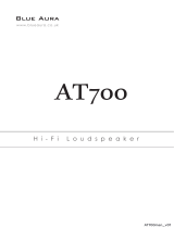
will accept either spade or banana plugs. If not bi-wiring fit the link wires from the accessories pack, as shown in figure 2.
Arrange the connections so that the right hand amplifier channel terminals are connected to the right hand loudspeaker as viewed from
the listening position.
Correct polarity of the connections between the amplifier and speakers is essential. The positive terminal on the amplifier left channel,
marked + (plus) or coloured red, must be connected to the positive terminal on the left loudspeaker. The negative terminal on the
amplifier left channel, marked - (minus) or coloured black, must be connected to the negative terminal on the left loudspeaker.
Repeat this connection for the right speaker.
Good quality cables and tight, well-made connections are necessary to eliminate resistive losses and maintain the correct damping of
the loudspeaker by the amplifier.
If the cables and connections have been made correctly as described above the loudspeakers will be automatically in phase with each
other. However if phasing is felt to be incorrect (for example, diffuse stereo image, lack of bass) then apply the following test:
Place the loudspeakers side by side and play a monophonic signal from the amplifier, choosing the programme material with
a strong bass content. If phasing is correct bass will be full and rich. If incorrect there will be very little bass due to cancellation
effects. Incorrect phasing can be remedied by reversing the connecting leads to one loudspeaker (at either the amplifier or the
loudspeaker terminals but not both).
Note: Be certain to ensure that the amplifier is switched off when connecting or disconnecting loudspeaker leads. Accidentally shorting
the loudspeaker leads together can damage some amplifiers. Such damage is outside warranty provisions.
In combining the best of traditional crafts and the latest production and design skills Tannoy presents the Canterbury loudspeaker.
The Canterbury embodies the Tannoy philosophy. Cabinets in selected hardwoods are hand finished and polished to a standard that
is unsurpassed.
The Canterbury 15 SE is a truly special loudspeaker made only to order with
certification and personalised nameplate. The speaker uses the classic Alcomax
3 version of the famous Tannoy Dual Concentric™ driver. This magnet system
endows the Dual Concentric™ with an exceptional transient response and
increased sensitivity. This high performance driver is installed in braced
birch-ply cabinet with burr walnut veneers and solid walnut mouldings. Acrolink
99.9999% (6N) high purity copper wiring is used throughout, together with
specially selected crossover components, including Hovland capacitors. High
frequency energy can be tailored through a high current gold-plated switch
block with controls for both treble energy and roll off. Low frequency adjustment is through the Tannoy Variable Distributed Port
System (VDPS). The specially designed twin-roll impregnated fabric surround used on the drive unit's cone, ensures midrange purity
combined with tight, controlled bass.

Tannoy - A Short History
In the early days of broadcasting radio sets needed both low and high voltage DC power that had to be supplied by batteries. The lead
acid batteries used in the radio sets of the time needed regular recharging.
In London, in 1926, Guy R. Fountain perfected a new type of electrical rectifier with the aim of designing a charger more suitable for
use in the house. His rectifier consisted of two dis-similar metals held in a special electrolyte solution. One metal was Tantalum and
the other an alloy of Lead. So successful was this invention that Guy Fountain founded a British Company called Tannoy (a contraction
of the words 'Tantalum' and 'Alloy'). Tannoy soon became internationally known and highly regarded in all aspects of sound reproduction.
Moving coil loudspeakers with DC energised magnets began Tannoy's continued success in the field of loudspeaker technology.
A discrete two-way loudspeaker system followed in 1933 and shortly after a range of microphones and loudspeakers capable of high
power handling.
Tannoy has always been at the front of the communications revolution, developing its own equipment and production technology.
The company built a fund of knowledge and experience, that has proved invaluable in the development of loudspeakers for a truly wide
range of applications. The now famous Tannoy Dual Concentric™ principle was created and developed under Guy Fountain's direction
around 1950. It is highly regarded by music enthusiasts, and recording and broadcast studios because of its unique properties in faithfully
reproducing sound to an unusually high quality standard.
Guy Fountain retired from the company in 1974 but the Tannoy company continues his philosophy dedicated to the accurate and
realistic reproduction of music for both enthusiasts and professionals around the world.
The Tannoy Research and Development unit has further refined the innovative Dual Concentric™ principle. Using the latest design
and material technologies, with sophisticated circuit techniques in crossover design, Tannoy has produced a loudspeaker system with
superb reproductive capabilities and exceptionally wide dynamic range.
Tannoy is now part of the TG Group, whose goal is to design, produce and distribute the best engineered, most recognised and respected
brands of high performance audio products in the world.
2
3
Initial Positioning
Locate the loudspeakers so that the favourite listening position is approximately 15° from the axes of the cabinets. The axes of both
cabinets should intersect at a point slightly in front of the listening position. Remember that the proximity of the loudspeakers to walls
and corners will affect the sound. Some experimentation will probably be needed to fine tune the stereo image depth and low frequency
sound quality. Close-to-wall positions - and room corners more so - have the effect of increasing very low frequency sound energy.
Reflective adjacent walls may upset the stereo image by causing unwanted reflections.
The loudspeakers are designed to be used at least 1m from any side wall or reflective surface and at least 0.5m away from a rear wall.
Only in this position will their exceptional stereo image depth capabilities be realised.
When the optimum position for the loudspeakers has been determined, position the three metal cups, provided in the accessories pack,
so that they sit under the three support cones, on the underside of the loudspeaker. These are positioned two at the front and one at
the rear. This will give maximum stability, and enable your loudspeakers to provide their full dynamics and resolution of detail.
WARNING: this operation should be carried out by two people, to avoid the risk of personal injury, should the speaker slip or fall.
Unpacking Instructions
Unfasten the bottom of the carton. Fold the end leaves out of the way and remove the packing tray to reveal the plinth and bottom
of the loudspeaker cabinet. Locate and remove accessories pack. Turn the carton and loudspeaker over so that the cabinet now stands
on the floor inside the carton. Lift the carton upwards to reveal the loudspeaker.
Examine all pieces of packing material and inspect the carton for signs of external damage. If there is evidence of excessive damage to
the packaging and resulting damage to the loudspeaker inform the carrier and supplier immediately. Always keep the packing in such
circumstances for subsequent examination.
Tannoy strongly suggests that you store the complete packaging set for possible future use.
Amplifier Connections
Connect the loudspeakers to the amplifier using a high quality cable. Your dealer will be able to make recommendations. The terminals
will accept either spade or banana plugs. If not bi-wiring fit the link wires from the accessories pack, as shown in figure 2.
Arrange the connections so that the right hand amplifier channel terminals are connected to the right hand loudspeaker as viewed from
the listening position.
Correct polarity of the connections between the amplifier and speakers is essential. The positive terminal on the amplifier left channel,
marked + (plus) or coloured red, must be connected to the positive terminal on the left loudspeaker. The negative terminal on the
amplifier left channel, marked - (minus) or coloured black, must be connected to the negative terminal on the left loudspeaker.
Repeat this connection for the right speaker.
Good quality cables and tight, well-made connections are necessary to eliminate resistive losses and maintain the correct damping of
the loudspeaker by the amplifier.
If the cables and connections have been made correctly as described above the loudspeakers will be automatically in phase with each
other. However if phasing is felt to be incorrect (for example, diffuse stereo image, lack of bass) then apply the following test:
Place the loudspeakers side by side and play a monophonic signal from the amplifier, choosing the programme material with
a strong bass content. If phasing is correct bass will be full and rich. If incorrect there will be very little bass due to cancellation
effects. Incorrect phasing can be remedied by reversing the connecting leads to one loudspeaker (at either the amplifier or the
loudspeaker terminals but not both).
Note: Be certain to ensure that the amplifier is switched off when connecting or disconnecting loudspeaker leads. Accidentally shorting
the loudspeaker leads together can damage some amplifiers. Such damage is outside warranty provisions.
In combining the best of traditional crafts and the latest production and design skills Tannoy presents the Canterbury loudspeaker.
The Canterbury embodies the Tannoy philosophy. Cabinets in selected hardwoods are hand finished and polished to a standard that
is unsurpassed.
The Canterbury 15 SE is a truly special loudspeaker made only to order with
certification and personalised nameplate. The speaker uses the classic Alcomax
3 version of the famous Tannoy Dual Concentric™ driver. This magnet system
endows the Dual Concentric™ with an exceptional transient response and
increased sensitivity. This high performance driver is installed in braced
birch-ply cabinet with burr walnut veneers and solid walnut mouldings. Acrolink
99.9999% (6N) high purity copper wiring is used throughout, together with
specially selected crossover components, including Hovland capacitors. High
frequency energy can be tailored through a high current gold-plated switch
block with controls for both treble energy and roll off. Low frequency adjustment is through the Tannoy Variable Distributed Port
System (VDPS). The specially designed twin-roll impregnated fabric surround used on the drive unit's cone, ensures midrange purity
combined with tight, controlled bass.

4
5
Loudspeakers need power signals to produce acoustic energy when reproducing music. The range of electrical currents passing down
the cable from the amplifier to the loudspeaker is very wide. In decibel terms this is called the dynamic range. Modern loudspeakers
are capable of resolving a dynamic range of at least 80dB with a suitable power amplifier.
An 80dB dynamic range corresponds to voltages of between 50 Volt and 0.005 Volt at the loudspeaker terminals or equivalent currents
of between 0.0006 and 6 Amp. This is a truly wide range of electrical signals to pass down one cable without some interactions causing
a loss of resolution in the very small signals.
When electricity passes down a wire or cable, what goes in at one end is unfortunately different from what comes out at the other.
The degree of loss or modification of a signal depends on the physical characteristics of the cable and the nature of the signal. Heavy
electrical currents flowing down thin conductors cause heating effects. Very high frequency signals passing along conductors or cables
of certain lengths cause electromagnetic radiation effects (aerials). Electrical cables are selected for minimum loss and maximum
information resolution considering the type of electrical signals they are designed to carry.
A good solution to the problem is to 'bi-wire' the loudspeakers to the amplifier. This means providing two separate sets of cables from
the power amplifier to each loudspeaker and dividing the electrical signals into high current, 'slow' signals and light current, 'fast' signals.
Of course, the loudspeaker must be fitted with two pairs of terminals to take the two sets of cables; your Tannoy loudspeakers are of
course equipped for just this type of connection.
Bi-Wiring Theory
Bi-wiring releases the full potential of the Tannoy Prestige loudspeakers. Two complete sets of cable are required.
Switch the amplifier off. Deal with each 'side' of the system separately.
Label two of the cables Left LF and Left HF (low frequency and high frequency). Do the same for the right pair. Undo the loudspeaker
terminals, remove and retain the Bi-wiring links so that the same polarity terminals are no longer joined.
It is essential to get the polarity correct. If your amplifier does not have separate output terminals for bass and treble then, at the amplifier
end of the cable, connect the Left LF+ and HF+ cables together. Then wire to the amplifier Left channel positive terminal marked +
(plus) or coloured red.
Connect the Left LF - and HF - cables together to the amplifier negative terminal marked - (minus) or black.
Note the polarity marking on the cable. At the loudspeaker end connect the cables marked Left LF+ and LF- to the appropriate left
speaker LF terminals. Connect the Left HF+ and HF- to the appropriate + and - left speaker HF terminals.
Make the same connections with the Right LF and HF cables.
For optimum performance, the earth connection on the terminal panel should be connected to the amplifier chassis earth or other
ground point. This screening effect can give an improvement in detail clarity, depending on the amplifier used. Optimum results are
achieved using a screened loudspeaker cable designed for such a system, such as the Tannoy TLC.
Switch on the amplifier with the volume turned down. Select a favourite source and carefully turn up the volume. Check that bass and
treble sounds come from both speakers. If not, switch off and remake the connections.
Bi-Wiring
High quality audio signals passing from power amplifier to loudspeaker are unusual in their demands on cable. Frequencies from 20Hz
to 20kHz (10 octaves or a ratio of 10,000:1) and currents of 80dB dynamic range (again a ratio of 10,000:1) have to coexist. The cable
also has to be capable of transmitting peak currents of at least 10 Amp without causing losses greater than 0.001 Amp (10 Amp divided
by the ratio 10,000).
These strict requirements on loudspeaker cables help explain why the sound quality from loudspeakers is so dependant on the physical
properties of the cables connecting them to the power amplifier.
Cables
FIG. 1
TERMINAL PANEL CONNECTIONS
HIGH FREQUENCY
POSITIVE(+) TERMINAL
'EARTH' OR 'GROUND' TERMINAL
LOW FREQUENCY
POSITIVE(+) TERMINAL
HIGH FREQUENCY
NEGATIVE(-) TERMINAL
LOW FREQUENCY
NEGATIVE(-) TERMINAL
HF+
HF
-
LF+
LF-
FIG. 2
SINGLE WIRE MODE AND EARTH (GROUND)
LEAD CONNECTION
TO RIGHT
SPEAKER
LINK WIRES IN PLACE
POWER AMPLIFIER
R
+ --
L
+
TO 'GROUND' OR
'EARTH' CONNECTION
ON AMPLIFIER (OPTIONAL)
HF+
HF
-
LF+
LF-
FIG. 3
BI-WIRE MODE AND EARTH (GROUND)
LEAD CONNECTION
TO RIGHT
SPEAKER
-+
R
-+
L
POWER AMPLIFIER
LINK WIRES REMOVED
TO 'GROUND' OR
'EARTH' CONNECTION
ON AMPLIFIER (OPTIONAL)
HF+
HF
-
LF+
LF-
FIG. 4
BI-AMPING MODE AND EARTH (GROUND)
LEAD CONNECTION
-+-
R
+
L
R
-
+
-
+
L
HIGH FREQUENCY
POWER AMPLIFIER
LOW FREQUENCY
POWER AMPLIFIER
LINK WIRES REMOVED
TO 'GROUND' OR
'EARTH' CONNECTION
ON HIGH FREQUENCY
AMPLIFIER (OPTIONAL)
TO RIGHT
SPEAKER
TO RIGHT
SPEAKER
HF+
HF
-
LF+
LF-

Grille Removal
Special acoustically transparent cloth is used in the grilles. However, for ultimate fidelity the enthusiast will find it is best to use these
loudspeakers with their grilles removed during listening.
The large front grille is removable for access to the front panel controls. Insert the key provided into the lock at the bottom of the main
grille assembly and turn anti-clockwise to release. Pull the bottom of the grille away from the cabinet; the grille will drop down from
its upper location. Take care not to damage the solid walnut lower part of the cabinet. To replace the grille engage the top of the grille
into the slot in the cabinet and push the grill into the recess. Apply slight pressure to the bottom whilst turning the key clockwise to
engage the lock.
Loudspeaker System Adjustment
Each loudspeaker is fitted with two controls located on the front baffle beneath the detachable grille. These high current switch blocks
are labelled ROLL OFF and ENERGY. They can be used to compensate for the varied acoustic characteristics of listening rooms.
The controls should be adjusted with the amplifier tone controls in the 'flat' or uncompensated position. Each loudspeaker should be
adjusted individually. This is most easily done by rotating the amplifier balance control to select first one loudspeaker and then
the other.
The ENERGY control has five positions. It allows the output of the high frequency compression drive unit to be increased or decreased
from the linear or 'flat' position over a frequency band from approximately 1kHz to 20kHz.
The ROLL OFF control has five positions (+2, level, -2, -4 and -6dB per octave) and provides adjustment at extreme high frequencies
from 5kHz to 20kHz.
The ENERGY control has a shelving effect over the 1kHz to 20kHz frequency band whereas the Kroll off control increases or decreases
the slope of the extreme high frequency response hinging about 5kHz.
The flattest, most linear response from the loudspeaker will be obtained with both controls set at the LEVEL position, and this position
should be used for initial listening tests. If the overall high frequency sound quality seems too prominent the -1.5 or -3 positions for
the ENERGY control should be tried. If the sound appears subdued in the treble region +1.5 or +3 settings may be preferred. Once
the ENERGY control setting has been established the ROLL OFF control can be adjusted to reduce or slightly increase the extreme
high frequency content if necessary.
Remember the changes that can be made by moving either control from one position to another are subtle. They may not easily be
heard if the programme material has very little content in the frequency band under consideration. Choose a well balanced piece of
music with a full spectrum of sound. The correct setting will be found when the loudspeakers are no longer evident and only the musical
performance is heard.
The low frequency output of the loudspeaker in the range 25 to 100Hz may be adjusted by operating the two sliding port openings
on each side of the cabinet. Each port may be varied from fully open (full distributed port operation, both port slides in upper position)
to fully closed (infinite baffle or acoustic suspension operation, both port slides in downward position). When both ports are fully open
a very full rich bass response will be heard, when fully closed the bass response becomes more subdued. The correct setting is a matter
for personal preference and local acoustic conditions. With one port open and the other closed the bass response will be 'level' and
this position should be used for initial evaluation.
Running in
Like all loudspeakers, the drive unit in your Canterbury 15 SE requires a while to reach optimum performance, as the stresses in the
materials relax - especially in the suspension system. For this reason, it is beneficial to run the system at fairly high levels at normal
room temperature, for approximately 20 hours to achieve best results.
6
7
Tannoy Dual Concentric Drive Unit
One of the unique advantages of the Tannoy Dual Concentric™ principle is that the low and high frequency sound radiation is generated
on the same axis. The high frequency unit is mounted behind, and concentrically with, the low frequency unit. High frequency sound
radiates from the centre of the low frequency unit through a carefully designed high frequency exponential horn. Low and high
frequencies are therefore fully integrated at source. It is this feature that gives the Dual Concentric™ driver such unique sound
reproduction qualities.
There are other significant benefits. The high frequency unit does not obstruct the low frequency unit in any way (a unique feature
when compared with other so called coaxial systems). Polar dispersion of sound is symmetrical in both horizontal and vertical planes.
By careful crossover network design the virtual acoustic sources of the high and low frequency units can be made to occupy the same
point on the axis. Therefore the total sound appears to emanate from a single point source located slightly behind the drive unit. This
means that a full and accurate stereo image can be recreated by the loudspeakers when fed from a high quality stereo source.
The low frequency section of the Dual Concentric™ driver has exceptional power handling and dynamic range. The low frequency
cone piston is produced from selected paper pulp. This is specially treated to absorb internal resonance modes. The completed cone
is fitted with unique rigid reinforcing members to attain a very high stiffness to mass ratio thereby preserving piston action over the
operating frequency range.
The twin roll fabric surround is also damped and shaped correctly to terminate the moving cone and provide optimum compliance and
linearity at large excursions. The cone piston is driven by a high power motor system consisting of a four-layer coil suspended in a
precision magnetic air gap. The coil is wound with a special high temperature adhesive system and individually cured to ensure reliable
operation at high peak power inputs. The shape of the low frequency cone is arranged to provide optimum dispersion of audio frequencies
at both the high and low ends of the spectrum. The cone flare continues the high frequency horn profile to ensure a smooth transition
at the crossover point.
The Low Frequency Section
The high frequency driver consists of a wide dynamic range compression unit giving superb transient performance with a smooth
uncoloured response. The compression unit feeds acoustic power through a multiple phase compensating device to the throat of a solid
steel acoustic horn. This horn provides an acoustic impedance transformation to match the compression unit radiation into the listening
environment.
A magnesium alloy diaphragm formed by a specially developed five-stage process produces a piston with a very high stiffness to mass
ratio. Optimum molecular grain structure gives long term durability. A very low mass precision aluminium coil provides the driving
force for the diaphragm, with fine multistranded copper lead out wires to ensure reliability. A rear damped acoustic cavity controls the
compression driver response and ensures further correct acoustic impedance matching to the horn throat.
The response of the compression horn driver extends a full two octaves below the crossover frequency to eliminate colourations that
can arise through operation over the fundamental resonance region.
The High Frequency Section
An Alcomax 3 high energy magnet provides flux generation for both high frequency and low frequency driving motors. Precision air
gaps contain the magnetic flux surrounding each coil. The high frequency air gap has a unique shunt member to apportion the total
magnetic flux in the correct ratio between low and high frequency units. This gives an optimum acoustic balance. Precision machined,
low carbon steel pole pieces ensure unsaturated operation, linear flux fields and a high heat sinking capability. High power inputs can
therefore be handled with minimum change of impedance due to temperature effects. A very robust, high quality, precision pressure
die-cast chassis locates the whole magnet assembly and positions the moving parts with high accuracy. This provides long term reliability
and yet does not interfere with the acoustic radiation from the individual sections.
The Magnetic Circuit
PORTS
Loudspeaker in corner Closed
Loudspeaker clear of wall Open
Loudspeaker against wall Either Closed or One Open
How to adjust the Variable Distributed Port System for your
music in your room
The above suggestions are for guidance only. The music you listen to is also important - in general classical and light music will tend
to sound more natural with the ports closed. Rock music will sound more exciting with one or both ports open. Experiment with your
kind of music in your room. VDPS gives more choices of loudspeaker position in any room, this providing the opportunity to optimise
placement for the best stereo effect.
The aural effect of the variable distributed port may not be obvious unless the programme material contains bass frequencies within
the band 25 to 100Hz.
™

During the design of the crossover network the acoustic, mechanical and electrical interactions of the high and low frequency sections
have been fully analysed. The crossover is therefore an integral part of the design of the system. The crossover network provides complex
equalisation in both amplitude and phase for each section and fully integrates the response at the crossover point. All components are
high precision, low-loss and thermally stable. Specially selected components of the highest quality are used, such as Hovland polypropylene
capacitors, non-inductive thick film resistors with extensive heatsinking, and very low loss laminated iron core inductors. Wiring is by
Acrolink 6N (99.9999%), having a large crystal structure and stable atomic arrangement.
All components in the crossover network are hard wired to eliminate unwanted metal-to-metal contact and ensure freedom from
vibration. The components are laid out to minimise inter component coupling and are placed well away from the driver magnetic field.
High current switch blocks with gold-plated screw terminals permit user adjustment of high frequency sound radiation to suit differing
listening environments.
The complementary design of crossover and drive units means that the loudspeaker system as a whole behaves as a minimum phase
system over the audio band and therefore the acoustic sources of the high and low frequency sections are aligned in time and space to
ensure accurate reproduction of stereo images.
The Crossover Network
A Note on Auditory Perception
Our hearing mechanism locates natural sound sources with great accuracy by using the naturally occurring phase differences (or arrival
times) at middle frequencies, and intensity differences at higher frequencies, between each of our ears. Naturally occurring sounds pass
through the air to the ears at constant speed (345 metres / second or 1132 feet / second). All frequencies travel at the same speed and
therefore a frequency independent time delay is associated with the distances involved. (The familiar time delay between a flash of
lightning and the associated clap of thunder is an example).
Human hearing relies on the constant nature of the time delay with the intensity to locate natural sounds accurately. A pair of Tannoy
Prestige loudspeakers can uniquely reconstruct stereo images and provide excellent localisation of recorded sounds. The Tannoy Dual
Concentric™ principle ensures that the source of sound at high frequencies is on the same axis as the source of sound at low frequencies.
The careful design of crossover network complements the drive unit to provide a coincident sound source at frequencies where the
human ear derives phase information for localisation. The loudspeaker system exhibits a time delay response that is in essence independent
of reproduced frequencies. In addition, the amplitude (or intensity) response is linear, smooth and consistent. This provides the correct
intensity information to recreate the original sound stage.
Care of the Cabinet
The cabinet is constructed from carefully selected solid walnut and walnut veneers that have been hand waxed before dispatch from
our finishing workshop.
To maintain the natural wood appearance it is important that only a wax of similar formulation is used.
A jar of specially formulated wax is included with each loudspeaker. This wax should be applied very sparingly with a soft lint-free cloth
(muslin for example) taking great care to avoid putting wax on the grille material. If necessary mask off the side grilles carefully with
clean paper, tucking it in and around the sides of the grilles. Work the wax into the wood covering a small area at a time.
In common with all solid wood furniture, exposure to extremes of heat, cold and varying humidity will cause the wood to ease slightly.
Therefore it is recommended that the loudspeaker is protected from environmental extremes to guard against any such occurrence.
8
9
Alcomax 3 is an unusually high energy permanent magnet. The unusual iron / nickel alloy is doped with cobalt, aluminium and other
rare metals to produce a magnetic material with very special properties. Alcomax 3 has a high remanent magnetism and energy product.
In other words, it magnetises to a high level and retains that unusual degree of magnetisation. Alcomax 3 is also an electrical conductor.
These properties give the Dual Concentric™ drive unit using an Alcomax 3 magnet an exceptionally clean transient response and
increased sensitivity.
Alcomax Magnet
Faultfinding
Tannoy loudspeakers are designed and manufactured to be reliable. When a fault occurs in a hi-fi system the effect is always heard
through the loudspeakers although they may not be the source of the fault. It is important to trace the cause of the problem as accurately
as possible.
A fault heard on one source (only CD or tape for instance) is most unlikely to be a loudspeaker problem. Loudspeakers do not generate
hum, hiss or rumble although high-quality, wide-bandwidth loudspeakers may emphasise such problems.
Tannoy Quality
An important part of Tannoy's design philosophy is to produce loudspeakers with a level of performance beyond the most exacting
specifications of contemporary source equipment.
Loudspeaker design is no longer a 'black art'. It is now possible to use computers to model designs and predict results. Comprehensive
test equipment is used to pin-point problems with cabinets or drive units; anechoic chambers help in producing accurate measurements.
Computer aided design (CAD) and sophisticated test equipment are used extensively at Tannoy but we always remember that listening
tests must be the final judge.
Tannoy follows a policy of stringent quality control procedures using sophisticated measurement facilities. Strict quality control is more
easily achieved because all the loudspeakers are built in-house at the Tannoy factory in Scotland. All drive units are designed and
manufactured by Tannoy. All incoming parts are thoroughly tested to ensure that they are as specified. Not only is all data computerised
but CAD ensures every loudspeaker meets or exceeds our exacting standards.
Warranty and Service
Tannoy Prestige loudspeakers will operate for many years without trouble provided they are cared for as instructed.
Tannoy Prestige loudspeakers are warranted against manufacturing defects in material or craftsmanship over a period of 5 years from
the date of purchase. This warranty is in addition to your statutory rights as a customer. Tannoy cannot however be held responsible
for failures caused by abuse, unauthorised modifications, improper operations or damage caused by faults elsewhere in your system.
The determination of the cause of failure will be made by Tannoy Ltd or its authorised Distributor or Service Agent based on physical
inspection of the failed parts.
If you suspect a problem with your loudspeakers then in the first instance discuss it with your Tannoy Dealer. The Dealer has the
expertise and experience to help you troubleshoot the system and assess the situation.
If you continue to have problems contact your Tannoy Distributor or Tannoy Customer Services at our Coatbridge address.
Due to our policy of continuous improvement, all specifications are subject to change without notice.
Caution
The high peak power handling of Tannoy loudspeakers will allow responsible use with larger amplifiers on wide dynamic range material.
Take care with any amplifier, irrespective of power output, to avoid abnormal conditions such as switch-on surges or output overload
(clipping) that may result in peaks of power greatly over the rated output.

10 11
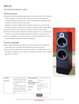
Technical Specifications
50-275 Watts per channel
140 Watts RMS
575 Watts peak
117.5dB (140 Watts RMS / 1m)
124.5dB (575 Watts peak / 1m)
96dB (2.83 Volts @ 1m)
8 Ohm
28Hz - 22kHz
90 degree conical
Less than 1.1% at 140 Watts RMS (50Hz - 20kHz)
380mm (15”) Dual Concentric™ utilising paper pulp cone
with twin roll impregnated fabric surround
52mm (2”) round wire voice coil
51mm (2”) edge-wound voice coil
Bi-wired, hard-wired passive, low loss,
2nd order LF, 2nd order compensated HF
1.1kHz
+
/- 3dB over 1.1kHz to 22kHz shelving
+2dB to -6dB per octave over 5.0kHz to 22kHz slope
Variable Distributed Port System
235 litres (8.3 cu. ft)
1100mm (43
1
/3”) x 680mm (26
3
/4”) x 480mm (18
7
/8”) (H x W x D)
63 kilograms (139 lbs)
Solid walnut with birch ply.
Internally crossbraced and heavily damped
1180mm (46
1
/2”) x 789mm (31
1
/16”) x 600mm (23
5
/8”) (H x W x D)
70 kilograms (154.3 lbs)
RECOMMENDED AMPLIFIER POWER
POWER RATING
MAXIMUM SPL
SENSITIVITY
NOMINAL IMPEDANCE
FREQUENCY RESPONSE
DISPERSION
TOTAL HARMONIC DISTORTION
DRIVE UNIT
DRIVER TYPE
LOW FREQUENCY
HIGH FREQUENCY
CROSSOVER
CROSSOVER TYPE
CROSSOVER FREQUENCY
ADJUSTMENTS
CABINET
ENCLOSURE TYPE
VOLUME
DIMENSIONS
WEIGHT
CONSTRUCTION
PACKAGE DETAIL
DIMENSIONS
WEIGHT
PERFORMANCE
NOTES

10 11
Technical Specifications
50-275 Watts per channel
140 Watts RMS
575 Watts peak
117.5dB (140 Watts RMS / 1m)
124.5dB (575 Watts peak / 1m)
96dB (2.83 Volts @ 1m)
8 Ohm
28Hz - 22kHz
90 degree conical
Less than 1.1% at 140 Watts RMS (50Hz - 20kHz)
380mm (15”) Dual Concentric™ utilising paper pulp cone
with twin roll impregnated fabric surround
52mm (2”) round wire voice coil
51mm (2”) edge-wound voice coil
Bi-wired, hard-wired passive, low loss,
2nd order LF, 2nd order compensated HF
1.1kHz
+
/- 3dB over 1.1kHz to 22kHz shelving
+2dB to -6dB per octave over 5.0kHz to 22kHz slope
Variable Distributed Port System
235 litres (8.3 cu. ft)
1100mm (43
1
/3”) x 680mm (26
3
/4”) x 480mm (18
7
/8”) (H x W x D)
63 kilograms (139 lbs)
Solid walnut with birch ply.
Internally crossbraced and heavily damped
1180mm (46
1
/2”) x 789mm (31
1
/16”) x 600mm (23
5
/8”) (H x W x D)
70 kilograms (154.3 lbs)
RECOMMENDED AMPLIFIER POWER
POWER RATING
MAXIMUM SPL
SENSITIVITY
NOMINAL IMPEDANCE
FREQUENCY RESPONSE
DISPERSION
TOTAL HARMONIC DISTORTION
DRIVE UNIT
DRIVER TYPE
LOW FREQUENCY
HIGH FREQUENCY
CROSSOVER
CROSSOVER TYPE
CROSSOVER FREQUENCY
ADJUSTMENTS
CABINET
ENCLOSURE TYPE
VOLUME
DIMENSIONS
WEIGHT
CONSTRUCTION
PACKAGE DETAIL
DIMENSIONS
WEIGHT
PERFORMANCE
NOTES

6481 0493
O W N E R ’ S M A N U A L
1926Estd.
Tannoy United Kingdom T: 00 44 (0) 1236 420199 E: enquiries@tannoy.com
Tannoy Deutschland T: 00 49 (0180) 1111 881 E: info@tannoy.com
Tannoy France T: 00 33 (0)1 7036 7473 E: ventes@tannoy.com
/