Ambiance Fireplaces Intrigue Owner's manual
- Category
- Fireplaces
- Type
- Owner's manual
This manual is also suitable for

JUNE 2012 INT-REV-05
—Do not store or use gasoline or other flammable vapors and liquids in the
vicinity of this or any other appliance.
WHAT TO DO IF YOU SMELL GAS:
◙ Do not light any appliance.
◙ Do not touch any electrical switch: do not use any phone in your building.
◙ Immediately call gas supplier from a neighbors phone. Follow the gas
supplier instructions.
◙ If you cannot reach your gas supplier, call the fire department.
— Installation and service must be performed by a qualified installer, service
agency or the gas supplier.
WARNING: If the information in these instructions is not followed exactly, a
fire or explosion may result, causing property damage, personal injury or loss
of life.
WARNING
Report No. 216-S-35b-6.5
This appliance may be installed in an aftermarket permanently located,
manufactured home (USA only) or mobile home where not prohibited by local
codes.
This appliance is only for use with the type of gas indicated on the rating plate.
This appliance is not convertible for use with other gases, unless a certified kit is
used.
HOT GLASS WILL CAUSE BURNS.
DO NOT TOUCH GLASS UNTIL COOLED.
NEVER ALLOW CHILDREN TO TOUCH GLASS.
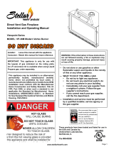
INSTALLATION AND OPERATING MANUAL
INSTALLER: LEAVE THIS MANUAL WITH THE APPLIANCE.
CONSUMER: RETAIN THIS MANUAL FOR FUTURE REFERENCE .
Direct Vent Gas Fireplace
Model: #INT-200
English and French Installation Manuals Available Through Your Local Dealer or Visit Our Website at www.kozyheat.com
Les manuels d’installation en anglais et en français sont disponibles chez votre détaillant local ou en visitant notre site Web : www.kozyheat.com


1
TABLE OF CONTENTS
TABLE OF CONTENTS
Table of Contents 1
SAFETY INFORMATION
Safety Information 2
COMMONWEALTH OF MASSACHUSETTS INFORMATION
Commonwealth of Massachusetts Information 3
SPECIFICATIONS
Fireplace Dimensions 4
Clearances 4
Components List 5
Installation Overview 5
Placement Clearance Requirements 5
PREPARE THE FIREPLACE
Stand-Off Assembly & Installation 6
Horizontal Vent Heat Shield Installation 7
Nailing Flange Assembly & Installation 7
FRAMING
Wall Enclosure Rough Opening 8
Minimum Finished Opening Dimensions 8
Horizontal Terminations 9
Vertical Terminations 9
TYPICAL INSTALLATION OPTIONS
Typical Installation Options 10
MANTEL REQUIREMENTS
Mantel Requirements 11
GLASS FRAME ASSEMBLY
Glass Frame Assembly Removal 11
Glass Frame Assembly Installation 11
GAS LINE CONNECTION
Gas Line Connection 12
LIGHT KIT COMPONENTS INSTALLATION (INT-200)
Light Kit Components Installation 12
VENTING
Approved Venting 13
Horizontal Terminations 13-14
Vertical Terminations 14
Restrictor Setting 14
Horizontal / Vertical Combination Terminations 15
VENTING (cont.)
Termination Vent Cap Location 16
Vent Termination Clearances 17
LOG SET INSTALLATION
Log Set Installation 18
CONTROL BOARD
Control Board Removal 19
Control Board Installation 20
GRILL SET
Grill Set Installation 21
Grill Set Removal 21
OPERATING INSTRUCTIONS
Wiring Schematics 22
Control System Components 23
System Operation 24-27
Lighting and Shutdown 28-29
Pressure Testing 30
FINALIZING THE INSTALLATION
Burner Tube Adjustment / Troubleshooting 31
Restrictor Troubleshooting 32
MAINTENANCE
Maintenance 33
TROUBLESHOOTING
Troubleshooting 34-35
CONVERSION KIT INSTRUCTIONS
Conversion Kit Instructions 36-37
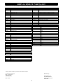
REPLACEMENT PARTS LIST
Replacement Parts List 38
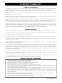
WARRANTY
Warranty 39-40

2
SAFETY INFORMATION
Installation and repair should be done only by a qualified service person. The appliance should be inspected by a
qualified service person before use. Annual inspection by a qualified service person is required to maintain warranty.
More frequent cleaning may be required due to excessive lint from carpeting, bedding materials, etc. It is imperative
that control compartments, burners and circulation air passageways of the appliance be kept clean.
If this appliance is installed directly on carpeting, tile or other combustible material other than wood flooring, the
appliance shall be installed on a metal or wood panel extending the full width and depth of the appliance.
Children and adults should be alerted to the hazards of high surface temperatures and should stay away to avoid burns
or clothing ignition.
Young children should be carefully supervised when they are in the same room as the appliance. Toddlers, young
children and others may be susceptible to accidental contact burns. A physical barrier is recommended if there are at
risk individuals in the house. To restrict access to a fireplace or stove, install an adjustable safety gate to keep toddlers,
young children and other at risk individuals out of the room and away from hot surfaces.
Clothing or other flammable material should not be placed on or near the appliance.
Adequate accessibility clearances for servicing and proper operation must be maintained.
This appliance must not share or be connected to a chimney flue serving any other appliance.
Keep area around the appliance clear of combustible materials, gasoline and other flammable vapor and liquids.
The flow of combustion and ventilation air must not be obstructed.
Due to high temperatures the appliance should be located out of traffic and away from furniture and draperies.
The glass front or any part removed for servicing the appliance must be replaced prior to operating the appliance.
Work should be done by a qualified service technician.
Clean glass only when cool and only with non-abrasive cleansers.
WARNING: DO NOT OPERATE APPLIANCE WITH THE GLASS/FRAME ASSEMBLY REMOVED, CRACKED
OR BROKEN. REPLACEMENT OF THE GLASS SHOULD ONLY BE PERFORMED BY A LICENSED OR
QUALIFIED SERVICE PERSON .
The glass assembly, Part #INT-057T, shall only be replaced as a complete unit, as supplied by Hussong Mfg. Co., Inc.
DO NOT SUBSTITUTE MATERIALS.
Do not strike or slam glass assembly.
Any safety screen or guard removed for servicing the appliance must be replaced prior to operating the appliance.
Under no circumstances should any solid fuel (wood, coal, paper or cardboard etc.) be used in this appliance.
Keep burner and control compartment clean.
Do not use this fireplace if any part has been under water. Immediately call a qualified service technician to inspect this
appliance and to replace any part of the control system and any gas control which has been under water.
This fireplace has been tested by OMNI-Test Laboratories, Portland, Oregon and complies with:
ANSI Z21.88-2009/CSA 2.33-2009, “Standard for Vented Gas Fireplace Heaters.”
CAN 2.17-M91 (R2009), “Gas-Fired for Use at High Altitudes.”
CAN/CSA P.4.1-09, “Testing Method for Measuring Annual Efficiency”.
This installation must conform with local codes, or in the absence of local codes, with the National Fuel Gas Code, ANSI Z223.1/NFPA 54,
or the Natural Gas and Propane Installation Code, CSA B149.1

3
COMMONWEALTH OF MASSACHUSETTS REQUIREMENTS
For all sidewall horizontally vented gas fueled equipment installed in every dwelling, building or structure used in whole or in part for residential purposes,
including those owned or operated by the Commonwealth and where the side wall exhaust vent termination is less than (7) feet above finished grade in the
area of the venting, including but not limited to decks and porches, the following requirements shall be satisfied:
INSTALLATION OF CARBON MONOXIDE DETECTORS
At time of installation of side wall horizontally vented gas fueled equipment, the installing plumber or gas-fitter shall observe that a hard wired carbon
monoxide detector with an alarm and battery back-up is installed on the floor level where the gas equipment is to be installed. In addition, the installing
plumber or gas-fitter shall observe that a battery operated or hard wired carbon monoxide detector is installed on each additional level of the dwelling,
building or structure served by the side wall horizontal vented gas fueled equipment. It shall be the responsibility of the property owner to secure the services
of qualified licensed professionals for the installation of hard wired carbon monoxide detectors.
In the event that the side wall horizontally vented gas fueled equipment is installed in a crawl space or attic, the hard wired carbon monoxide detector with
alarm and battery back-up may be installed on the next adjacent floor level.
In the event that the requirements of this subdivision can not be met at the time of completion of installation, the owner shall have a period of thirty (30) days
to comply with the above requirements; provided, however, that during said thirty (30) day period, a battery operated carbon monoxide detector with an
alarm shall be installed.
APPROVED CARBON MONOXIDE DETECTORS
Each carbon monoxide detector as required in accordance with the above provisions shall comply with NFPA 720 and be ANSI/UL 2 034 listed and IAS
certified.
SIGNAGE
A metal or plastic identification plate shall be permanently mounted to the exterior of the building at a minimum of eight (8) feet above grade directly in line
with the exhaust vent terminal for the horizontally vented gas fueled heating appliance or equipment. The sign shall read, in print no less the one-half inch
(1/2) in size, “GAS VENT DIRECTLY BELOW. KEEP CLEAR OF ALL OBSTRUCTIONS”.
INSPECTION
The state or local gas inspector of the side wall horizontally vented gas fueled equipment shall not approve the installation unless, upon inspection, the
inspector observes carbon monoxide detectors and signage installed in accordance with the provisions of 248 CMR 5.08 (2) (a) 1 through 4.
EXEMPTIONS
The following equipment is exempt from 248 CMR 5.08 (2) (a) 1 through 4:The equipment listed in Chapter 10 entitled “Equipment Not Required To Be
Vented” in the most current edition of NFPA 54 as adopted by the Board; and Product Approved side wall horizontally vented gas fueled equipment installed
in a room or structure separate from the dwelling, building or structure used in whole or in part for residential purposes.
MANUFACTURER REQUIREMENTS - GAS EQUIPMENT VENTING SYSTEM PROVIDED
When the manufacturer of Product Approved side wall horizontally vented gas equipment provides a venting system design or venting system components
with the equipment, the instructions provided by the manufacturer for installation of the equipment and the venting system shall include:
Detailed instructions for the installation of the venting system design or the venting system components; and
A complete parts list for the venting system design or venting system.
MANUFACTURER REQUIREMENTS - GAS EQUIPMENT VENTING SYSTEM NOT PROVIDED
When the manufacturer of Product Approved side wall horizontally vented gas equipment does not provide the parts for venting the flue gases, but identifies
“special venting systems”, the following requirements shall be satisfied by the manufacturer:
The referenced “special venting systems” instructions shall be included with the appliance or equipment installation instructions and;
The “special venting systems” shall be Product Approved by the Board, and the instructions for that system shall include a parts list and detailed
installation instructions.
A copy of all installation instructions for all Product Approved side wall horizontally vented gas fueled equipment, all venting instructions, all parts lists for
venting instructions, and/or all venting design instructions shall remain with the appliance or equipment at the completion of the installation.
NOTE The following requirements reference various Massachusetts and national codes not contained in this manual.

4
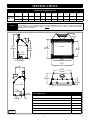
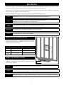
FIREPLACE DIMENSIONS
DESCRIPTION Height Width Back Width Depth Opening
Width
Glass Frame
Height
Stand-off
Height
Front to Vent
Center
(Vert. Term.)
Floor to Vent
Center
(Hor. Term.)
Front to
Angled Back
FIREPLACE
DIMENSIONS
INCHES 34-1/2 40-7/8 30-3/8 19 35-1/2 26-5/8 10 16-1/8 32-3/8 7-7/8
MILLIMETERS 876 1038 772 483 902 676 254 410 848 200
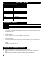
SPECIFICATIONS
CLEARANCES
Top of unit face to header (cement board may be used in this area). 10” (254mm)
From unit left & right sides and back 1/2” (13mm)
To flooring 0” (0mm)
Unit top to ceiling 31” (787mm)
Side of unit face to adjacent sidewall 3” (76mm)
Mantel 9” (229mm) deep from top of fireplace 12-1/2” (318mm)
Top of fireplace to 1” (25mm) trim 10” (254mm)
34
1
2
"
876mm
26
5
8
"
676mm
10"
254mm
35
1
2
"
902mm
40
7
8
"
1038mm
2
1
8
"
54mm
2
7
8
"
73mm
16
1
8
"
410mm
6
1
2
"
165mm
19"
483mm
30
3
8
"
772mm
7
7
8
"
200mm
33
3
8
"
848mm
44
1
2
"
1130mm
4
1
4
"
108mm
8
5
8
"
219mm
RIGHT SIDE
FRONT
LEFT SIDE
WARNING
All stand-off brackets must be attached to fireplace. Do not remove. Top stand-off brackets are not load bearing.
Non-combustible zone: Top stand-offs provide 10” (254mm) minimum clearance to header. Use only non-combustible
material in this area for entire width of fireplace. Do not use wood, sheetrock etc. in this zone. Other clearances apply.
All clearances must be maintained.
Figure 4a

5
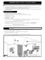
PLACEMENT CLEARANCE REQUIREMENTS
This fireplace must be installed on a level surface capable of supporting the fireplace and venting.
Fireplace must be placed directly on wood or non-combustible surface (not linoleum or carpet) extending entire depth and width of
fireplace.
Due to high surface temperatures, fireplace should be located out of traffic and away from furniture and draperies.
This fireplace may be installed in a bedroom.
Please be aware of the large amount of heat this fireplace will produce when determining a location.
INSTALLATION OVERVIEW
SPECIFICATIONS
1. Frame an opening for the fireplace, allowing for vent installation (top or rear) and type of installation (corner or flat wall application).
2. If masonry (optional) is used, prepare foundation for the masonry load. A lintel is required to support the added weight above fireplace.
3. Attach nailing flanges to fireplace.
4. Insert fireplace into framing.
5. Install hearth (if applicable).
6. Complete electrical hook-up. Install any standard or optional electrical components at this time.
7. Complete gas line installation.
8. Complete venting installation.
9. Secure fireplace to flooring through holes in outer box bottom and to framing with nailing flanges. Verify all clearances at this point.
10. Install facing material, mantel or cabinetry, allowing room for optional full face doors, if applicable.
11. Install logs.
12. Install grills and optional decorative doors / faces.
13. Verify proper operation of fireplace and all components.
INT-200 COMPONENTS LIST
PART NUMBER DESCRIPTION
INT-150 IPI Control Board Assembly
700-203 Manual Gas Shut-off Valve
INT-135 Burner Assembly
INT-G900 Refractory Set (back and sides)
INT-500 Log Package
INT-057T Glass Frame Assembly
600-002 Double Receptacle Assembly
500-TRF 4 pc. Grill Assembly
INT-408 Remote Control
INT-RLK Light Kit
INT-028 Fan Kit
NOTE The qualified installer should follow the procedure best suited for the installation.
NOTE
This appliance must be electrically grounded and connected in accordance with local codes, or in the absence of local codes, with the National
Electrical Code, ANSI/NFPA 70 Current Edition, or the Canadian Electrical Code CSA C22.1.

6
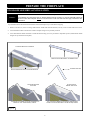
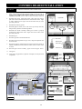
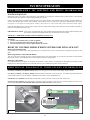
PREPARE THE FIREPLACE
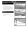
Top stand-off brackets and stand-off heat shields are attached to fireplace top in a flat state for shipping.
1. Remove and save (4) screws securing stand-off heat shields and stand-off brackets, and (4) screws located under these items.
2. Form stand-off brackets as shown and re-attach to fireplace using screws previously removed.
3. Form stand-off heat shields and attach to stand-off brackets using (8) screws provided in components packet. (Stand-off heat shield
flanges face up and to front of fireplace).
STAND-OFF ASSEMBLY & INSTALLATION
STAND-OFF BRACKETS AS SHIPPED
REMOVE SCREWS SECURING STAND-OFF BRACKETS
ALIGN HOLES IN FORMED STAND-OFFS WITH HOLES IN
FIREPLACE TOP. SECURE WITH (4) SCREWS.
FORM STAND-OFF BY BENDING AT PERFORATIONS
FORMED STAND-OFF
STAND-OFF BRACKETS
INSTALLED
ALIGN HOLES IN FORMED STAND-OFF HEAT SHIELDS WITH
HOLES IN STAND-OFF BRACKETS. SECURE WITH (8) SCREWS.
STAND-OFF HEAT
SHIELDS INSTALLED
WARNING
Top stand-off brackets and stand-off heat shields must be attached to fireplace. Do not remove. These items are not load bearing.
Non-combustible zone: Stand-offs provide 10” (254mm) minimum clearance to header. Use only non-combustible material in
this area for entire width of fireplace. Do not use wood, sheetrock etc. in this zone. Other clearances apply. All clearances must
be maintained.
Figure 6a

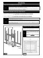
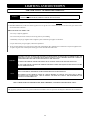
7
When installed, nailing flanges provide minimum 1/2” (13mm) clearance from fireplace sides.
FRAMING STUD
NAILING FLANGE
FRAMING STUD
1/2” (13mm)
CLEARANCE
STAND-OFF
FRONT VIEW
AS SHIPPED
NAILING FLANGES
INSTALLED
PREPARE THE FIREPLACE
HORIZONTAL VENT HEAT SHIELD INSTALLATION
1. Loosen, but do not remove center three screws at back of fireplace as shown.
2. Bend horizontal heat shield at perforation to a 45° angle. Slide (3) slots on
horizontal vent heat shield under loosened screws. Re-tighten screws.
Attach here.
Tighten screws.
NAILING FLANGE ASSEMBLY & INSTALLATION
1. Remove (4) nailing flanges from fireplace sides.
2. With the 1/2” (13mm) stand-offs on nailing flanges facing away from fireplace, align nailing flange with holes on outside corners of
fireplace. Secure with screws through slots in nailing flanges (additional screws provided in components packet).
3. Bend perforation on nailing flange until parallel with fireplace face. Do not bend toward fireplace face.
4. Position framing stud against 1/2” (13mm) stand-off (located on backside of nailing flange). Secure with nails or screws.
NAILING FLANGE
1/2” (13mm)
CLEARANCE
STAND-OFF
TOP VIEW
Figure 7b
Figure 7a
NOTE Depending on facing material, tabs can be adjusted forward or back wards up to 1/2” (13mm).
CAUTION Never permanently remove these assemblies from fireplace - they must be secured in place regardless of finish material used.
IMPORTANT
The horizontal vent heat shield must be installed when using a 45-degree elbow to horizontally position the vent system.
EXCEPTION: Corner installations

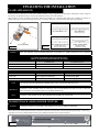
8
MINIMUM FINISHED OPENING DIMENSIONS
FRAMING
WALL ENCLOSURE ROUGH OPENING
HORIZONTAL TERMINATION: 44-1/2”(1130mm) High x 41-3/8”(1051mm) Wide x 21-1/2” (546mm) Deep.
1/2” (13mm) clearance at back and sides of fireplace must be maintained.
VERTICAL TERMINATION: 44-1/2”(1130mm) High x 41-3/8”(1051mm) Wide x 21-1/2” (546mm) Deep.
1/2” (13mm) clearance at back and sides of fireplace must be maintained.
Refer to vent manufacturer installation instructions to determine
vent framing dimensions.
Minimum:
21-1/2”(546mm)
44-1/2”
(1130mm)
41-3/8”
(1051mm)
Hearth
Height
OPTIONAL FULL DOOR FACE DIMENSIONS
If installing an optional full door face, please refer below for full
face dimensions before applying facing material.
36-5/32”
(918mm)
41-3/4”
(1060mm)
Figure 8a
Figure 8b
NOTE
Provide adequate clearance in front of fireplace to operate lower grill, open and close optional full door face doors, access
components, installation of gas line, fan, etc. See Figure 8b.
NOTE
Consider height of hearth finish material (stone, brick,
marble etc.) when building fireplace platform. Bottom of
fireplace must be level with finished hearth to allow for
lower grill operation and proper fit of optional decorative
full door faces.
1/2” (13mm) side overlap applies to both sides of face.
Illustrations show True Dimensions. We recommend
1/4” (6mm) clearance on all sides to allow for uneven finish
material.
IMPORTANT
Framing dimensions should allow for wall covering thickness and fireplace facing materials. If using a hearth, adjust rough
opening size as necessary to maintain at least minimum clearance requirements.
Non-combustible facing material may be applied over (but not directly to) fireplace face. This will prevent facing material from
falling off due to heat expansion. Do not obstruct the flow of ventilation air.
WARNING
P R O V I D E A D E Q U A T E C L E A R A N C E S A R O U N D A I R O P E N I N G S I N T O T H E C O M B U S T I O N C H A M B E R .
DO NOT OBSTRUCT UPPER AND LOWER GRILL OPENINGS. ROOM AIR ENTERS THROUGH LOWER PASSAGE, IS HEATED
AND EXITS THROUGH UPPER PASSAGE. BLOCKING THESE PASSAGES MAY RESULT IN OVERHEATING, CREATING A
POTENTIALLY HAZARDOUS SITUATION.

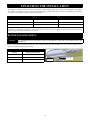
9
Determine exact position of your fireplace, including hearth height, width, and depth, (if applicable). If possible, place fireplace in such a
manner that vent termination will be placed between two studs, eliminating the need for additional framing.
If masonry is to be used (optional), prepare the necessary foundation for the masonry load. When masonry construction is used, a lintel
must be used over top of fireplace to support the added weight.
Build hearth to desired size and height. If a hearth extension is desired, combustible material may be used.
Follow vent pipe manufacturer’s installation instructions for horizontal
terminations. Include required vent manufacturer’s wall pass-thru clearances
when determining framing dimensions.
HORIZONTAL TERMINATIONS
Follow vent pipe manufacturer’s installation instructions for vertical
terminations. A minimum 1” (25mm) clearance on all sides of vertical
vent pipe must be maintained.
VERTICAL TERMINATIONS
FRAMING
MINIMUM HORIZONTAL FRAMING DIMENSIONS
VENT PIPE CENTER (A) FRAMED OPENING TOP (B)
RIGID PIPE 33-3/8” (848mm) Per vent manufacturer requirements
FLEX PIPE 36-7/8” (937mm) Per vent manufacturer requirements
Figure 9a
NOTE
Consider height of hearth finish material (stone, brick, etc.) when building fireplace platform. Bottom of fireplace must be level
with finished hearth to allow for lower grill operation and proper fit of optional decorative full door faces.
WARNING DO NOT RECESS VENT CAP INTO WALL OR SIDING.
WARNING
Install fireplace on hard metal or wood surface extending the full width and depth of fireplace.
Minimum platform size: 40-7/8” (1038mm) wide x 19” (483mm) deep.
IMPORTANT
Vent cap location must be in compliance with guidelines on page 16 of this manual.
FIRE
HAZARD
Do NOT install directly on carpeting, vinyl, or any combustible material other than wood.
CAUTION
Cold air transfer area. The surrounding fireplace chase must comply with all clearances as outlined in this manual and be
constructed in compliance with local building codes. Outside walls should be insulated to prevent cold air from entering room.
CAUTION Due to high temperatures, this fireplace should be located out of traffic areas and away from furniture and draperies.
NOTE The included Horizontal Vent Heat Shield is not used for vertical configurations.

10
1
2
"
13mm
19
1
2
"
495mm
41
3
8
"
1051mm
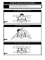
TYPICAL INSTALLATION OPTIONS
TYPICAL HORIZONTAL INSTALLATION
TYPICAL VERTICAL INSTALLATION
TYPICAL CORNER INSTALLATION
1
2
"
13mm
1
2
"
13mm
69
3
4
"
1772mm
49
1
4
"
1251mm
34
7
8
"
886mm
2"
51mm
41
3
8
"
1051mm
1"
25mm
21"
533mm
Figure 10a
Figure 10c
Figure 10b
MINIMUM:
21 ½” (546mm)
MINIMUM:
21 ½” (546mm)
IMPORTANT
The horizontal heat shield included with this fireplace must be installed when incorporating minimum horizontal venting.
This applies to Nat. and LP minimum horizontal venting configurations.
Horizontal vent heat shield not shown in illustrations below for clarity purposes only.

11
10"
254mm
12
1
2
"
318mm
14
1
2
"
368mm
16
1
2
"
419mm
13" (330mm)
11" (279mm)
9" (229mm)
13
1
2
"
343mm
1"
25mm
MANTEL REQUIREMENTS
Rigid pipe: 1” (25mm) above elbow for entire width and depth (behind header) of fireplace.
Flexible venting: 1” (25mm) above elbow for entire width and depth (behind header) of fireplace.
NON-COMBUSTIBLE ZONE:
NON-COMBUSTIBLE MATERIAL ONLY
NON-COMBUSTIBLE ZONE:
No materials allowed on top of fireplace within shaded
area for the entire width and depth of fireplace. This
air space must remain open.
HORIZONTAL VENT HEAT
GLASS FRAME ASSEMBLY
1. Making sure wide lip of glass frame assembly is at bottom and narrow lip at top, place assembly onto fireplace front.
2. Pull top handles out and down to secure glass frame assembly top.
3. Pull bottom handles out and up to secure glass frame assembly bottom.
REMOVE GLASS FRAME ASSEMBLY
1. Locate spring-loaded handles securing glass frame assembly at top & bottom of firebox.
2. Pull bottom handles out and down to release glass frame assembly bottom.
3. Pull top handles out and up to release glass frame assembly top.
4. Remove glass frame assembly from fireplace.
Pull latches out and down to release glass frame assembly bottom.
Pull latches out and up to attach glass frame assembly bottom.
Pull latches out and up to release glass frame assembly top.
Pull latches out and down to attach glass frame assembly top.
Narrow lip at top of glass frame assembly.
Wide lip at bottom of glass frame assembly.
Figure 11b
Figure 11a
SIDE VIEW
WARNING
TOP STAND-OFF BRACKETS MUST BE ASSEMBLED AND ATTACHED TO FIREPLACE. DO NOT REMOVE.
STAND-OFF BRACKETS ARE NOT LOAD BEARING.
CAUTION
TO PREVENT GLASS FRAME ASSEMBLY FROM FALLING FROM FIREPLACE AND BECOMING DAMAGED, FOLLOW THESE
INSTRUCTIONS EXACTLY WHEN REMOVING AND INSTALLING GLASS FRAME ASSEMBLY.
INSTALL GLASS FRAME ASSEMBLY

12
This fireplace is manufactured for use with Natural Gas. Follow instructions included with conversion kit if converting to LP gas.
(Sold separately).
GAS LINE CONNECTION
GAS CONVERSION
NATURAL GAS LP GAS
MINIMUM INLET GAS PRESSURE 5” WC (1.25 kPa) (7” WC (1.74 kPa) recommended) 12” WC (2.99 kPa) (recommended)
MAXIMUM INLET GAS PRESSURE 10.5” WC (2.62 kPa) 13” WC (3.24 kPa)
MANIFOLD PRESSURE (HI) 3.8” WC (.95 kPa) 11” WC (2.74 kPa)
MANIFOLD PRESSURE (LO) 1.1” WC (.27 kPa) 2.9 (.72 kPa)
ORIFICE SIZE #57 & #37 #63 & #51
INPUT BTU/hr. (kW) 39,500 (11.58 kW) 39,500 (11.58 kW)
MINIMUM INPUT BTU/hr. (kW) 19,500 (5.72 kW) 19,500 (5.72 kW)
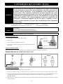
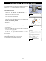
LIGHT KIT COMPONENT INSTALLATION
1. Install halogen bulbs (included in components
packet) into lamp bases.
2. Place amber light filters into light cylinders.
CAUTION Disconnect all electrical power from fireplace before performing this task.
NOTE To avoid damage and prolong the life of halogen bulbs, never touch with bare hands. Always use a soft cloth when handling.
CAUTION
Installation of the gas line must only be done by a qualified person in accordance with local building codes, if any.
If not, follow ANSI 223.1.
Commonwealth of Massachusetts: Installation must be done by a licensed plumber of gas fitter.
NOTE
A listed (and Commonwealth of Massachusetts approved) 1/2” (13mm) T-handle manual shut-off valve and flexible gas
connector (included) are connected to the 1/2” (13mm) control valve inlet. If substituting for these components, please consult
local codes for compliance.
This fireplace is equipped with a 3/8”(10mm) x 18” (457mm) long flexible gas connector and manual shut-off valve. The gas
line should be run to the point of connection where the shut-off valve and flexible gas line will connect.
The appliance and its individual shutoff valve must be disconnected from the gas supply piping system during any pressure
testing of that system at pressures in excess of ½ psi (3.5 kPa).
The appliance must be isolated from the gas supply piping system by closing its individual manual shut-off valve during any
pressure testing of the gas line at test pressures equal to or less than ½ psi (3.5 kPa).
For high altitude installations, consult the local gas distributor or the authority having jurisdiction for proper rating methods.
IMPORTANT
The efficiency rating of this appliance is a product of thermal efficiency rating determined under continuous operating
conditions and was determined independently of any installed system.
Figure 12a

13
Refer to the vent systems manufacturer's installation manual for complete installation instructions.
Installation must conform with the venting requirements and restrictions as outlined in this manual.
Provide a means for visually checking vent connection to fireplace after fireplace is installed.
Simpson Dura-Vent DV-GS 5” x 8” and 4” x 6-5/8” -with reducer (horizontal and vertical terminations).
Metal Fab Direct Chimney System 5” x 8” (horizontal and vertical terminations).
ICC Direct Chimney Systems 5” x 8” (horizontal and vertical terminations).
Selkirk-Metalbestos Chimney Systems 5” x 8” and 4” x 6-5/8” -with reducer (horizontal and vertical terminations).
BDM 5” x 8” Chimney Systems (horizontal and vertical terminations).
Security 5” x 8” Chimney Systems (horizontal and vertical terminations).
Ameri-Vent 5” x 8” Chimney Systems (horizontal and vertical terminations).
HORIZONTAL VENT SYSTEM CLEARANCES
TOP BOTTOM SIDES
ALL APPROVED VENTING
1 inches (25mm) 1 inch (25mm) 1 inch (25mm)
APPROVED VENTING
HORIZONTAL MIN. / MAX.
MINIMUM: 45° elbow + 6” (152mm) horizontal + termination cap.
MAXIMUM: 45° elbow + 6ft. (1.83m) + termination cap.
VENTING
The following statement applies to horizontal, vertical, or a combination of horizontal/vertical elbows:
For each additional 90° elbow used after first elbow, 3ft. (914mm) must be subtracted from maximum allowed venting. For each 45° elbow
used, 1-1/2ft. (457mm) must be subtracted from maximum venting allowed.
ELBOWS
HORIZONTAL MIN. / MAX. (with reducer)
NAT GAS MINIMUM: 2ft (610mm) vertical + reducer + 90° elbow + 6” (152mm) horizontal + termination cap.
NAT GAS MAXIMUM: 2ft. (610mm)vertical + reducer + 90° elbow + 12ft. (3.66m) + termination cap.
LP GAS MINIMUM: 2ft. (610mm)vertical + reducer + 90° elbow + 6” (152mm) + termination cap.
LP GAS MAXIMUM: 2ft. (610mm) vertical + reducer + 90° elbow + 2ft. (610mm) + termination cap.
LP GAS MAXIMUM: 3ft. (914mm) vertical + reducer + 90° elbow + 12ft. (3.66m) + termination cap.
IMPORTANT
Wall pass-thru required for all horizontal runs. Refer to vent manufacturer to determine which pass-thru will work best for
your application and wall thickness.
The horizontal vent heat shield must be installed when using a 45-degree elbow to horizontally position the vent system.
Exception: corner installations.
NOTE (2) 45° degree elbows may be used in place of (1) 90° elbow.
IMPORTANT
Consult the local and national installation codes to assure adequate combustion and ventilation air is available.
Flame height and appearance will vary depending upon venting configuration and type of fuel used.
Venting requirements apply to both Natural and LP gas.
HORIZONTAL TERMINATIONS

14
VERTICAL TERMINATIONS
MINIMUM: 45˚ elbow + 2ft. (610mm) + termination cap.
MAXIMUM: 45˚ elbow + 50ft. (15.2m) + termination cap.
MAXIMUM (if using reducer):
45° elbow + 2ft. (610mm) + reducer + 48ft. (14.63m) + term. cap.
RESTRICTOR SETTING
VERTICAL VENT SYSTEM CLEARANCES
SIDES
ALL APPROVED VERTICALVENTING
1 inch (25mm)
VENTING
HORIZONTAL TERMINATIONS
TYPICAL CORNER INSTALLATION
Termination Cap
Minimum: 2ft. (610mm)
Maximum: 50ft. (15.2m)
Pipe
45° Elbow
45° Elbow
Termination Cap
Termination Cap
Minimum: 6in. (152mm)
Maximum: 6ft. (1.83m)
45° Elbow
Horizontal Vent Heat Shield
90° Elbow
Figure 14b
Figure 14c
Figure 14a
NOTE Horizontal sections require 1/4” (6mm) rise for every 12” (305mm) of travel.
CAUTION This gas appliance must not be connected to or joined with any other chimney flue serving another appliance.
VERTICAL MIN. / MAX.
Figure 14d
This fireplace is shipped with the restrictor set in open position. Follow chart for recommended settings based on venting
configuration.
It is important to remember each installation is unique and affected by various factors including venting configuration, altitude and climate.
Therefore, after fireplace installation is complete, restrictor setting adjustment may be necessary. Page 32 has information on restrictor
recommendations depending on burner flame appearance after installation is completed.
Restrictor setting adjustment handle is located at top front of firebox. Remove glass frame assembly to access. Loosen screw, adjust setting,
tighten screw and reinstall glass frame assembly.
Loosen screw
RECOMMENDED RESTRICTOR SETTINGS
VENTING RESTRICTOR POSITION
Min. - 20ft. (6.1m) FULL OPEN (handle pulled forward)
20 ft. (6.1m) - 35ft. (10.7m) PARTIAL OPEN (handle set to center)
35ft. (10.7m) - 50ft. (15.2m) CLOSED (handle pushed back)

15
HORIZONTAL & VERTICAL COMBINATION TERMINATIONS
MAXIMUM: 18ft. (5.49m) horizontal + 18ft. (5.49m) vertical + cap. [36ft. (10.98m) total].
MAXIMUM (with reducer): 45° elbow + 2ft. (610mm) + reducer + 16ft. (4.88m) hor. /vert + 18ft. (5.49m) hor / vert + term. cap.
VENTING
0
2
4
6
8
10
12
14
16
20
22
18
24
26
28
30
40
38
36
34
32
0 2
4
6 8 10 12 14 16 18 20 22 24 26 28 30
(6.1m)
(12.9m)
(6.1m)
(9.14m)
HORIZONTAL / VERTICAL COMBINATION:
(5.49m) 18' Vertical
(5.49m) 18' Horizontal
Termination must be
within shaded area
(ft.)
50
48
46
44
42
(15.2m)
52
Figure 15a
ATTENTION
IF INSTALLING WITH RIGID-TO-FLEX PIPE SYSTEMS:
More than a 30 degree bend constitutes a 45 degree elbow.
More than a 45 degree bend constitutes a 90 degree elbow.
More than a 90 degree bend is not permissible.
IMPORTANT
Wall pass-thru required for all horizontal runs. Refer to vent manufacturer to determine which pass-thru will work best for
your application and wall thickness.
The horizontal vent heat shield must be installed when using a 45-degree elbow to horizontally position the vent system.
Exception: corner installations.

16
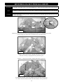
1. Terminations against vinyl siding must use a vinyl siding protector. Follow instructions included.
2. DO NOT RECESS TERMINATION KIT INTO OUTSIDE BUILDING MATERIALS - i.e.: brick, stone, siding, etc. If necessary,
extend framing so that termination kit will be exposed once building materials are installed.
3. Vent termination must not be located where it will become plugged by snow or other material. The flow of combustion and ventilation
air must be not obstructed.
A. Above grade, veranda, porch, deck, balcony - 12" (305mm).
B. Operable window or door - CANADA: 12" (305mm). US: 9” (229mm).
C. Permanently closed window* - 12" (305mm) (recommended to prevent condensation on window).
D. Ventilated soffit* - 24" (610mm).
E. Unventilated soffit* - 12" (305mm).
F. Outside corner* - 3" (76mm).
G. Inside corner* - 10” (254mm).
H. Meter / Regulator: CANADA: Not to be installed above a gas meter/regulator assembly within 3ft. (914mm) horizontally from the
centerline of the regulator within a height of 15ft. (4.57m). US*.
I. Gas Service regulator vent outlet : CANADA: 3ft. (914mm). US*.
J. Non-mechanical air supply inlet to building or the combustion air inlet to any other appliance. CANADA: 12" (305mm).
US: 9” (229mm).
K. Mechanical air supply inlet. CANADA: 6ft. (1.83m) US: 3ft. (914mm) above if within 10ft. (3.05m) horizontally.
Massachusetts installations: 10ft. (3.05m).
L. Above paved side-walk or paved driveway located on public property - 7ft. (2.13m). US*
This gas appliance must not be connected to a chimney serving any other appliance.
TERMINATION VENT CAP LOCATION
LOCATION CLEARANCES
M. Under veranda, porch, deck, or balcony (must be fully opened on a minimum of 2 sides) - 12" (305mm).
N. Between two horizontal terminations - 12" (305mm).
O. Between two vertical terminations - 12" (305mm). Terminations may be same height.
P. Above furnace exhaust or inlet - 12" (305mm).
*Clearance must be in accordance with local installation codes & the requirements of the gas supplier.
Figure 26a
Denotes where installation not allowed
Figure 16a
NOTE
A vent cannot be located directly above a side-walk or paved driveway that is located between two single family dwellings and
serves both dwellings.

17
Roof Pitch H (Min.) Ft. H (Min.) m
Flat to 6/12 1.0 0.30
Over 6/12 to 7/12 1.25 0.38
Over 7/12 to 8/12 1.5 0.46
Over 8/12 to 9/12 2.0 0.61
Over 9/12 to 10/12 2.5 0.76
Over 10/12 to 11/12 3.25 0.99
Over 11/12 to 12/12 4.0 1.22
Over 12/12 to 14/12 5.0 1.52
Over 14/12 to 16/12 6.0 1.83
Over 16/12 to 18/12 7.0 2.13
Over 18/12 to 20/12 7.5 2.27
Over 20/12 to 21/12 8.0 2.44
VENT TERMINATION CLEARANCES
VENTING (Vertical Cap Requirements)
CAUTION This appliance must not be connected to or joined with any chimney flue serving any other appliance.
Figure 17a
* If vent is closer than 1 ft. (305mm), it must terminate at least
2ft. (0.61m) higher than any portion of a building within 10ft.
(3.05m) of the vent.
Approved Cap
Approved vent pipe
Roof pitch = X/12
Discharge opening
H - Minimum height from roof to lowest discharge opening
12
X
Minimum
*1 ft. (305mm)
H

18
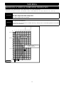
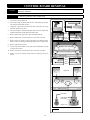
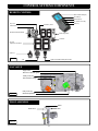
#INT-500 LOG SET INSTALLATION
#3
#2
#1
Install #5 - #10 logs as shown above, aligning with notches in base logs,
and in the case of log #7, aligning notch in log with burner grate.
#4
#9
#8
#7
#6
#5
#10
Install #11 - #12 logs as shown below, aligning with notches in lower logs.
#11
#12
Randomly place “klinkers” in this area. Do not place klinkers directly on burner ports.
Use a steel or stiff bristle brush to distribute Rock Wool Embers onto logs and burner.
#4
Figure 18b
Figure 18c
Figure 18a
Align holes in bottom of logs #1, #2 & #3 with mounting pins on burner cover, setting down into position.
Position #4 logs (2) as shown above. Do not allow logs to block burner ports.
NOTE Log numbers are located on the bottom of each log. Refer to following instructions and illustrations for proper placement.
CAUTION
Do not place logs directly over burner port holes. Improper log placement may affect flame appearance and cause excessive soot
to build up on logs and glass.
ATTENTION If converting to LP (propane) gas do so now before installing log set. Follow instructions included with kit. (Sold separately).
Page is loading ...
Page is loading ...
Page is loading ...
Page is loading ...
Page is loading ...
Page is loading ...
Page is loading ...
Page is loading ...
Page is loading ...
Page is loading ...
Page is loading ...
Page is loading ...
Page is loading ...
Page is loading ...
Page is loading ...
Page is loading ...
Page is loading ...
Page is loading ...
Page is loading ...
Page is loading ...
Page is loading ...
Page is loading ...
Page is loading ...
Page is loading ...
-
 1
1
-
 2
2
-
 3
3
-
 4
4
-
 5
5
-
 6
6
-
 7
7
-
 8
8
-
 9
9
-
 10
10
-
 11
11
-
 12
12
-
 13
13
-
 14
14
-
 15
15
-
 16
16
-
 17
17
-
 18
18
-
 19
19
-
 20
20
-
 21
21
-
 22
22
-
 23
23
-
 24
24
-
 25
25
-
 26
26
-
 27
27
-
 28
28
-
 29
29
-
 30
30
-
 31
31
-
 32
32
-
 33
33
-
 34
34
-
 35
35
-
 36
36
-
 37
37
-
 38
38
-
 39
39
-
 40
40
-
 41
41
-
 42
42
-
 43
43
-
 44
44


Ambiance Fireplaces Intrigue Owner's manual
- Category
- Fireplaces
- Type
- Owner's manual
- This manual is also suitable for
Ask a question and I''ll find the answer in the document
Finding information in a document is now easier with AI
Related papers

Other documents
-
kozy heat Intrigue Owner's manual
-
Kozyheat Bayport 41 Owner's manual
-
-
Philips BMT1853/00 Datasheet
-
-
-
-
 Stellar Hearth VP-36M Installation guide
-
-
