Page is loading ...

TOTAL
3 Year Warranty
CUSTOMER
SATISFACTION
Series 945
User’s Manual
Watlow Controls
1241 Bundy Blvd., P.O. Box 5580, Winona, Minnesota USA 55987-5580, Phone: 507/454-5300, Fax: 507/452-4507
0600-0017-0000 Rev A
August, 1994
Supersedes without change: W945-MA40-9432
$10.00
Made in the U.S.A.
Recycled Paper At Least 10% Postconsumer Waste
1/4 DIN
Microprocessor-Based
Auto-tuning Control

Starting Out
How to Use the Manual
2
WATLOW Series 945 User's Manual
Contents
Notes
Informational notes alert you to important details. When
you see a note icon, look for an explanation in the margin.
or
Safety Information
Boldface safety information protects both you and your
equipment. Please be attentive to them. Here are
explanations:
The WARNING symbol in the wide text column alerts you
to a "WARNING," a safety hazard which could affect you
and the equipment. A full explanation is in the narrow
column on the outside of the page.
The CAUTION symbol in the wide text column alerts you to
a "CAUTION," a safety or functional hazard which could
affect your equipment or its performance. A full explana-
tion is in the narrow column on the outside of the page.
Technical Assistance
If you encounter a problem with your Watlow control,
review all of your configuration information to verify that
your selections are consistent with your application...
Inputs, Outputs, Alarms, Limits, etc. If the problem persists
after checking the above, you can get technical assistance
by dialing: 1-507-454-5300
An Application Engineer will discuss your problem with you.
Please have the following information available:
• Complete model number • Serial Number
• All configuration information • User's Manual
The model and serial numbers can be found on the outside
of the case.
Your Feedback
Your comments or suggestions on this manual are wel-
come, please send them to: Technical Writer, Watlow
Controls, 1241 Bundy Blvd., P.O. Box 5580, Winona, MN
55987-5580, or phone 507/454-5300. The Watlow Series
945 User's Manual and integral software are copyrighted
by Watlow Winona, Inc., © 1989, with all rights reserved.
blr0392
Page Item
Chapter 1
3 Starting Out With The Watlow Series 945
3 General Description
Chapter 2
4 How To Install And Wire The Series 945
4 Installation Procedure
4 Dimensional Information
5 Wiring the Series 945
5 Sensor Installation Guidelines
6 Input Wiring
7 Output 1 Wiring
8 Output 2 Wiring
9 Alarm Wiring
10 Retransmit Wiring
11 System Wiring Examples
Chapter 3
12 How To Use The Keys And Displays
12 Series 945 Keys and Displays
Chapter 4
13 How To Setup The Series 945
13 How to Set the DIP Switch
13 Entering Setup Menu
14 Setup Parameters
17 Setup Menu Table
18 Operation Parameters
20 Operation Menu Table
Chapter 5
21 How To Tune And Operate
21 Auto-tuning
22 Manual Tuning
23 Manual and Automatic Operation
24 Changing the Position of an Alarms Jumper
25 Using Alarms
26 Error Code Messages
27 Error Code Actions
28 Appendix 1
28 Noise Sources
28 Decreasing Noise Sensitivity
29 Eliminating Noise
30 Checking For Ground Loops
30 Noise Suppression Devices Available…
31 Line Filtering Configurations For Controls
32 Appendix 2
32 Entering the Calibration Menu
33 Restoring Factory Calibration
35 Calibration Procedures
39 Glossary
41 Index
42 Specifications
43 Model Number Information
43 Returns
43 Warranty
ç

Starting Out
Getting Started, Chapter 1
3
WATLOW Series 945 User's Manual
Starting Out
Chapter 1
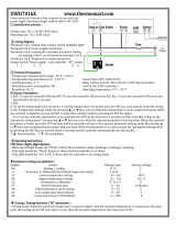
The Watlow Series 945,
A Microprocessor-Based Control
Figure 1 -
Series 945 Input and
Output Overview
Output 1
Auto-tuning
(Heat only)
Output 1 or 2
Percent Power
Retransmit Output
Dual Alarms
Output 2 -
Heat, Cool or None
Output 1 -
Heat or Cool
Dual Outputs -
PID or ON/OFF, User Selectable
Single Input -
Type J, K, T, N, R, S, B, C or Pt2
Thermocouple, RTD or Process
Remote Set
Point Input -
0-5VDC or 4-20mA
Process Set Point
(Up to 10 Slaves)
RS-422A, RS423A (RS-232C
compatible), or EIA-485
Optional Computer Interface
General Description
Welcome to the Watlow Series 945, a 1/4 DIN microprocessor-based temperature
control. It has a single input, remote set point input, dual output, and dual alarm.
The 945 is an auto-tuning control when Output 1 is in the heat mode, and features
Automatic/Manual capability with bumpless transfer. In the Auto mode, the 945 has
closed loop control with sensory feedback, while the Manual mode has open loop
control with user defined output power level. The 945 accepts a variety of thermo-
couples, as shown above, along with RTD, or process input. The primary output is
heat or cool, while the secondary output can be heat, cool or none. An optional
retransmit output is offered in place of one of the alarms. Selectable as retransmit
of set point or process variable. Units with communications feature data logging
with user selectable table, chart or SPC (Statistical Process Control) printout of data.
With the Series 945 you can select either PID or ON/OFF for Output 1 or 2. Input a
complete set of PID parameters for both outputs, including proportional band, reset/
integral and rate/derivative. By setting either output's proportional band to zero, the
Series 945 becomes a simple ON/OFF control with the switching differential select-
able under the HYS (hysteresis) parameter in the Setup menu.
Operator-friendly features include automatic LED indicators to aid in monitoring and
setup, as well as a calibration offset at the front panel. The Watlow Series 945
automatically stores all information in a non-volatile memory.

Install and Wire, Chapter 2
4
WATLOW Series 945 User's Manual
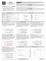
1. Make a panel cutout per the dimensions given below. Your panel thickness can
be from 0.06" to 0.25" (1.52 to 6.35 mm).
2. Remove the 945 from its case by turning the front panel screw 90° counterclock-
wise (CCW). Grip the bezel firmly and pull the control out of the case.
3. Place the case in the cutout you just made. Attach the two mounting brackets,
shipped with your unit, either to the top and bottom, or to both sides of the unit.
Tighten the brackets securely against your panel.
4. Insert the control chassis into its case and press the bezel to seat it. Turn the
front panel screw 90° clockwise (CW) to lock the control in place.
Installation
Figure 2 -
Series 945
Panel Cutout and
Unit Dimensions
CAUTION:
The front panel
screw turns 90°
only. Do not apply
excessive force or
turn the screw more
than 90°.
!
Chapter 2
How to Install and Wire the Series 945
LOCK
!
3.62" to 3.65" sq.
(92 to 92.25 mm)
Panel
Cutout
3.63" X 3.63"
(92.08 X 92.08 mm)
3.8" sq.
(97 mm)
3.6" ± 0.015"
(90 mm ± 0.381)
0.92"
(23 mm)
6.0"
(152 mm)
Figure 3 -
How to Open the
Series 945.
Bezel 0.17" sq.
Dimension (4 mm)
Mounting Bracket
Panel
Figure 4 -
Mounting the
Series 945 Case.

Install and Wire, Chapter 2
5
WATLOW Series 945 User's Manual
Power Wiring
How to Wire the Series 945
The Series 945 wiring is illustrated by model number option. Check the terminal
designation sticker on the control and compare your model number to those shown
here and also the model number breakdown on the inside back cover of this manual.
Series 945 internal circuits appear "inside" the line drawing of the 945, while
connections and terminal designations appear "outside" the line drawing. All
outputs are referenced to a de-energized state. The final wiring figure is a typical
system example.
When you apply power without a sensorinput on the terminal strip, the 945
displays "- - - -" in the upper display, and "0" in the lower display. Press AUTO/
MAN twice, and ER 7 is displayed for one second. This error indicates an open
sensor or A/D error. Remove power to the control and connect the sensor properly,
see Page 6. All wiring and fusing must conform to the National Electric Code and
to any locally applicable codes as well.
120 VAC
L1
Fuse
L2
Earth Ground
11
12
13
240 VAC
L1
Fuses
L2
Earth Ground
10
12
13
Figure 6 -
240 VAC Power
Wiring
Figure 5 -
120 VAC Power
Wiring
WARNING:
To avoid potential
electric shock, use
National Electric
Code (NEC) safety
practices when
wiring and connect-
ing this unit to a
power source and to
electrical sensors or
peripheral devices.
Sensor Installation Guidelines
We suggest you mount the sensor at a location in your process or system where it
reads an average temperature. Choose a point that will adequately represent the
process temperature without being overly reactive.
For thermocouple inputs: Use an isolated or ungrounded thermocouple if an
external 4-20mA output device with a non-isolated circuit common is connected.
Extension wire must be of the same alloy as the thermocouple itself to limit errors.
For RTD inputs: There could be a +2°F input error for every 1 of lead length
resistance when using a 2 wire RTD. That resistance, when added to the RTD
element resistance, will result in erroneous input to the instrument. To overcome
this problem, use a 3 wire RTD sensor, which compensates for lead length resis-
tance. When extension wire is used for a 3-wire RTD, all wires must have the
same electrical resistance (i.e. same gauge, copper stranded).
For 0-5VDC or 4-20mA process inputs: The rL and rH settings scale the display
to match the measured range of the process signal. For 0-5VDC process input, the
impedance is 100KΩ. For 4-20mA process input, the impedance is 249Ω.

Install and Wire, Chapter 2
6
WATLOW Series 945 User's Manual
Thermocouple Input
Input Wiring
Figure 7 -
Thermocouple
Input Wiring
+
-
7
9
4
5
6
4
5
6
Jumper #5 to #6
for 2 Wire RTD
+
-
1
3
V
DC
Figure 9 -
0 - 5 VDC Process
Input Wiring.
Figure 8 -
2 or 3 wire RTD
Input Wiring.
These input connections are also used in conjunction with T/C and RTD
sensor types when using the remote set point input.
0 - 5VDC Process or Remote Set Point Input
Input impedance: 100KΩ
945A - 2 _ _ _ - _ 000
945A - 3 _ _ _ - _ 000
RTD, 2 or 3 Wire
945A - 2 _ _ _ - _ 000
945A - 3 _ _ _ - _ 000
4 - 20mA Process or Remote Set Point Input
945A - 1 _ _ _ - _ 000
945A - 2 _ _ _ - _ 000
945A - 3 _ _ _ - _ 000
945A - 4 _ _ _ - _ 000
1
2
3
+
-
DC
I
A jumper must be
installed between
Terminal #2 and 3.
945A - 2 _ _ _ - _ 000
945A - 3 _ _ _ - _ 000
4-20mA process input: 249Ω.
Figure 10 -
4-20mA Process
Input Wiring.
(-) = Red

Install and Wire, Chapter 2
7
WATLOW Series 945 User's Manual
Output 1 - Solid State Relay With Contact Suppression
Output 1 Wiring
Mechanical Relay, Form C, 6 Amp
17
16
18
N.O.
COM.
External
Load
Fuse
L1
L2
N.C.
Off state impedance: 20KΩ min.
17
16
Switched DC, Open Collector,
Non-Isolated
Logic
Switch
External
Load
+
-
+
-
Output 1 - Switched DC Output (Open Collector)
Output 1 - Process, 4 - 20mA
Output 1 - Mechanical Relay, 6 Amp, Form C
945A - _ B _ _ - _ 000
945A - _ C _ _ - _ 000
945A - _ D _ _ - _ 000
Figure 12 -
Switched DC
(Open Collector)
Figure 13 -
6 Amp Mechanical
Relay
NOTE:
Minimum load
resistance is 500 .
Available current is
22mA maximum.
Typical voltage drop
across a 1K load is
12 to 19 volts.
Figure 11 -
Solid State Relay
With Contact
Suppression
NOTE:
This output is
supplied with an arc
suppression snubber
across the output
terminals. High
impedance loads may
remain energized
even though the
output device is
turned OFF.
N.O.
COM.
External
Load
Fuse
L1
L2
18
17
Off state impedance: 31MΩ max.
Suppression
Off state impedance: 20K max.
18
17
Process, 4-20 mA, Non-Isolated
External
Load
-
+
IDC
+
-
Load impedance: 600Ω max.
945A - _ F _ _ - _ 000
Figure 14 -
Process, 4-20mA

Install and Wire, Chapter 2
8
WATLOW Series 945 User's Manual
Output 1 & 2 Wiring
Output 1 - Process, 0 - 5VDC
N.O.
COM.
External
Load
Fuse
L1
L2
18
17
Solid State Relay, Form A, 0.5 Amp
Off state impedance: 31MΩ max.
945A - _ H _ _ - _ 000
945A - _ K _ _ - _ 000
Output 2 - Solid State Relay With Contact Suppression
Output 1 - Solid State Relay Without Contact Suppression
Figure 16 -
Solid State Relay
Without Contact
Suppression
Figure 15 -
Process, 0 - 5VDC
945A - _ _ B _ - _ 000
Figure 17 -
Solid State Relay
With Contact
Suppression
NOTE:
This output is supplied
with an arc suppression
snubber across the
output terminals. High
impedance loads may
remain energized even
though the output device
is turned OFF.
18
17
External
Load
-
++
-
Load impedance: 10KΩ min.
COM.
N.O.
External
Load
Fuse
L1
L2
15
14
Off state impedance: 20KΩ max.
Suppression
15
14
Switched DC, Open Collector,
Non-Isolated
Logic
Switch
External
Load
-
+
Load impedance: 10KΩ min.
945A - _ _ C _ - _ 000
Output 2 - Switched DC Output (Open Collector)
Figure 18 -
Switched DC Output
(Open Collector)
NOTE:
Minimum load resis-
tance is 500
Ω. Available
current is 22mA
maximum. Typical
voltage drop across a
1K
Ω load is 12 to 19
volts.

Install and Wire, Chapter 2
9
WATLOW Series 945 User's Manual
Output 2 & Alarms
Output 2 - Mechanical Relay, 6 Amp, Form A
Figure 19 -
6 Amp Mechanical
Relay
NOTE:
This output is
supplied with an arc
suppression snubber
across the output
terminals. High
impedance loads may
remain energized
even though the
output device is
turned OFF.
Output 2 - Solid State Relay Without Contact Suppression
COM.
N.O.
External
Load
Fuse
L1
L2
15
14
Solid State Relay, Form A, 0.5 Amp
Off state impedance: 31MΩ max.
945A - _ _ K _ - _ 000
945A- _ _ _ 1 - _ 000
Alarm Output - Mechanical Relay, 6 Amp, Single Form A or B
For more information on alarms and alarm jumper selection,
see Chapter 5.
Figure 20 -
Solid State Relay
Without Contact
Suppression
Figure 21 -
Alarms
Option 1 Wiring.
15
14
N.O.
COM.
Fuse
L1
L2
External
Load
Off state impedance: 20KΩ min.
Suppression
945A - _ _ D _ - _ 000
Load
Fuse
L1
L2
26
27
Output #3
Off state impedance: 20KΩ min.
Suppression
Alarm Output - Mechanical Relay, 6 Amp, Dual Form A or B
945A- _ _ _ 2 - _ 000
Figure 22 -
Alarms
Option 2 Wiring.
Load
Fuse
L1
L2
Load
Fuse
L1
L2
24
25
26
27
Off state impedance: 20KΩ min.
Output #4
Output #3
Suppression

Install and Wire, Chapter 2
10
WATLOW Series 945 User's Manual
Alarm/Retransmit
Mechanical Relay, 6 Amp, Form A or B/0 - 5VDC Retransmit
Figure 23 -
Alarm/Retransmit
Option 3 Wiring.
NOTE:
This output is sup-
plied with an arc
suppression snubber
across the output
terminals. High
impedance loads may
remain energized
even though the
output device is
turned OFF.
Figure 24 -
Alarm/Retransmit
Option 4 Wiring.
Process, 0-5VDC non-isolated
25
24
External
Load
-
+
+
-
Load impedance: 10KΩ min.
945A- _ _ _ 3 - _ 000
945A- _ _ _ 4 - _ 000
945A- _ _ _ 5 - _ 000
Figure 25 -
Retransmit
Option 5 Wiring.
0 - 5VDC Retransmit Output
Mechanical Relay, 6 Amp, Form A or B/4 - 20mA Retransmit
Load impedance: 10K min. for 4-20mA. Relay offstate impedance: 20K .
Load
Fuse
L1
L2
26
27
25
24
External
Load
-
+
+
-
Load impedance: 10KΩ min. for 0-5VDC. Relay offstate impedance: 20KΩ.
Load
Fuse
L1
L2
26
27
25
24
External
Load
-
+
IDC
+
-
945A- _ _ _ 6 - _ 000
4 - 20mA Retransmit Output
Figure 26 -
Retransmit
Option 6 Wiring.
25
24
External
Load
-
+
IDC
+
-
Load impedance: 600Ω max.

Install and Wire, Chapter 2
11
WATLOW Series 945 User's Manual
Wiring Example
WARNING:
All wiring and fusing must conform to the National Electric Code NFPA70 and to
any locally applicable codes. Contact your local board for additional information.
Failure to observe NEC safety guidelines could result in injury to personnel.
CAUTION:
Watlow mercury relays are designed to be used only with resistive loads.
Figure 27 -
System Wiring
Example
1 4-20, 0-5 +
2 4-20, Jumper to 3
3 4-20, 0-5 -
4 S1
5 S2
6 S3
7 T.C. +
8 Not Used
9 T.C. -
10 L1 240V
11 L1 120V
12 L2
13 Earth Ground
14 N.O.
15 Com.
16 Com.
17 N.O.
18 N.C.
Terminal Function
Output #1
Output #2
945A-2DD0-A000
945A-2DD0-A000
Rear View
(+)
9
7
12
13
11
16
17
(-)
L1
L2
CO
M
N.O.
Ground
Mercury
Relay for
Control
120 VAC
Fuse
140A-16XX-6000
High Limit Control
(-)
(+)
Coil
Heater
Process Sensor
Limit Sensor
Normally Open
Momentary
Switch
Red
High Limit
Mechanical
Contactor
Earth Ground
1CR
Series 945
Temperature
Control
Hg
1
L1
11
L2
12
2
7
9
16
4
5
17
1 2
1 2
1
2
1 2
(+)
(-)
3
6
8
15
16
Heater
1CR-1 2CR-1
Hg
17 18
L1 L2
7
9
10
TC (+)
TC (-)
11
12
945A-2DD0-A000
140A-1601-6000
N.O.
N.C.
2
2CR
13
Hi Temp. Light
1
2
3
4
5
6
7
8
9
10
11
12
Series 140
Limit
Control
Reset
COM
R
COM
ç
ç

Keys and Displays, Chapter 3
12
WATLOW Series 945 User's Manual
Keys/Displays
After 1 minute with no key activations, the control reverts to the process value in the
upper display and the set point in the lower display.
Chapter 3
How to Use the Keys and Displays
Figure 28 -
Series 945
Keys and Displays.
A1 & A2
When lit, these LEDs tell you
when Alarms 1 or 2 are active.
Only appears on those units
with alarms option.
L 1 & L2
When lit, these LED's
tell you when Output 1
or Output 2 is ener-
gized. L2 only appears
if your unit has the #2
output hardware.
Upper Display
Red, 0.56" (14 mm) high,
seven segment, four digit
LED display, indicating
either process actual
temperature, the operating
parameter values, or an
open sensor. When power-
ing up, the Process display
will be blank for 8 seconds.
Lower Display
Red 0.56" (14 mm) high, seven
segment, four digit LED
display, indicating the set
point, operation parameters,
menu parameters, and error
or alarm codes.
Auto/Manual LED
Lit when the control is in
Manual operation. Press the
key twice to enter Auto opera-
tion. A blinking Auto/Manual
LED indicates that pressing
the AUTO/MAN key toggles
between Auto and Manual.
After 5 seconds without press-
ing the AUTO/MAN key, the
LED stops blinking, and re-
turns to its previous state.
AUTO/MAN Key
Pressed once, it clears any
latched alarms. If the key is
pressed again within 5
seconds, the control toggles
between the Auto and Manual
mode. While in the Manual
mode, percent power is always
displayed in the lower display.
MODE Key
Steps the control
through the Operating
menu; also, in the Auto
mode, enters new data
selected.
Front Panel
Locking Screw
Secures or releases
the control chassis
from its case.
UP/DOWN keys
When pressed simultaneously for 3 seconds, the
Setup Menu appears displaying the LOC
parameter. At the LOC parameter, continue to
press the UP/DOWN keys simultaneously , and
the Calibration Menu will appear.
UP Key
Increases the value of
the displayed parame-
ter. A single touch in-
creases the value by
one. Hold the key
down to increase the
value at a rapid rate.
New data is self enter-
ing in 5 seconds.
DOWN Key
Decreases the value of
the displayed parame-
ter. A single touch de-
creases the value by
one. Hold the key down
to decrease the value
at a rapid rate. New
data is self entering in 5
seconds.

Setup, Chapter 4
13
WATLOW Series 945 User's Manual
Setup
Chapter 4
How To Setup The Series 945
Setting up the Series 945 is a simple process. First configure the 945's features to
your application in the Setup Menu, and then enter values in the Operating Menu.
Use the MODE key to move through the menus and the UP/DOWN keys to select
data.
At this point, enter the Calibration menu by pressing the UP/DOWN keys simulta-
neously for 3 seconds. Selecting US or SI under the dFL parameter determines the
following: If selected as US, rate, reset, °F and proportional band in degrees will
appear. If selected as SI, integral, derivative, °C and proportional band in % of span
will appear. See Appendix II to change this parameter.
How to Set the DIP Switch
The Watlow Series 945 has a Dual In-line Package (DIP) switch inside the control on
the A007-1954 circuit board (middle board). The location of the board and switches
appear below. The switches are clearly numbered. When Switch #1 is ON, the Setup
parameters can be viewed but not changed. Switch #2 is not used. The factory
default is OFF.
Entering the Setup Menu
Enter the Setup Menu by pressing the UP/DOWN keys simultaneously for 3 seconds.
The lower display shows the LOC parameter, and the upper display shows its current
level. All keys are inactive until you release both keys. You can reach the LOC
parameter from anywhere.
You will not see all parameters in this menu, depending on the unit's configuration and
model number. After stepping through the menu it returns to the control set point
parameter under the Operation menu.
Figure 29 -
DIP Switch Location
and Orientation
Hardware Lockout of
SETUP Parameters
Battery Discharge for
Storage
1
2
(Factory default is OFF)
A007-1954
Control Chassis - Top View
Figure 30 -
Entering the
Setup Menu
Not Used

Setup, Chapter 4
14
WATLOW Series 945 User's Manual
Setup Menu
Figure 31 -
The Setup Menu
NOTE:
The rL and rH
parameters are used
to scale the display
for process inputs,
and/or will scale the
retransmit range for
process output. rL
and rH also limit the
range of the set
point.
= Parameter may or may not appear
depending on control configuration.
= Only appear if your unit has com-
munications. See the Series 945
data communications manual for more
information on these parameters.
M
LOC
In
dEC
C _ F
rL
rH
Ot 1
HYS1
Ot 2
HYS2
AL 1
LAt1
HYS3
AL 2
LAt2
HYS4
SIL
rtd
bAUd
Prot
Addr
Log
Int
tAg
( )
( )
( )
( )
( )
( )
( )
( )
( )
( )
( )
( )
( )
( )
( )
( )
( )
( )
( )
( )
( )
( )
( )
( )
75
( )
dAtA
rSP
( )
LSL
USL
LinE
Mon
dAY
HOUr
( )
( )
( )
( )
( )
( )
( )
YEAr
Min
( )
[Set Point]
User lock out
Input type
Remote set point
Decimal place
Celcius_Fahrenhei
t
Range low
Range high
Output 1
Hysteresis 1
Output 2
Hysteresis 2
Alarm 1
Latching for alarm 1
Hysteresis 3
Alarm 2
Latching for alarm
2
Hysteresis 4
Silence alarm
RTD calibration curve
Baud rate
Data bits and parity
Protocol type
Address
Logging printout
Lower spec limit
Upper spec limit
Lines per pag
e
Current year
Current mont
h
Current day
Real time hour
Real time minutes
Time interva
l
Variables to transmit
Ot4
( )
Output
4
tbS
( )
Time base
Setup Parameters
When you are at the top of the menu, the Series 945 displays the user level of
operation in the upper display, and the LOC parameter in the lower display.
Press the MODE key and the value of the next parameter appears in the upper
display, the prompt appears in the lower display. For units with process input, see
the L-r parameter on Page 20 for how LOC is affected.
Lock: Selects the level of operator lockout. Range: 0 - 3 Default: 0
LOC 0: All operating parameters may be viewed or changed. Manual operation is
permitted. Bumpless transfer to manual operation can occur on sensor break.
LOC 1: The set point, actual, and L-r (if rSP is enabled) are the only visible parameters,
set point is adjustable in this level. Manual operation is permitted. Bumpless
transfer to manual operation can occur on sensor break.
LOC 2: The set point, actual, and L-r (if rSP is enabled) are the only visible parameters,
set point is adjustable in this level. Manual operation is not permitted.
Bumpless transfer is defeated, outputs are disabled on sensor break.
LOC 3: The set point and actual are the only visible parameters, set point is not
adjustable in this level of lockout. Manual operation is not permitted. Bumpless
transfer is defeated, outputs are disabled on sensor break.
LOC

Setup, Chapter 4
15
WATLOW Series 945 User's Manual
Setup
In
rSP
dEC
C _ F
rL
rH
Ot1
HYS1
Ot2
HYS2
Input: Selects the sensor input type. Only those input types which are compatible
with your unit will appear. See the model number information for your type.
Range: J, K (appears as H), t, n, c, r, S, b, Pt2, rtd, rt.d, 0-5, 420 Default: J or r
Remote Set Point: Enables models with process input capability to accept a remote
set point signal from another device. This parameter only appears if In = Thermo-
couple or RTD. Range: OFF, 0-5, 420 Default: OFF
Decimal: Selects the location of the decimal point for all process related data. This
parameter only appears if the In parameter is 0-5 or 420.
Range: 0, 0.0, 0.00 Default: 0
Celsius _ Fahrenheit: Selects the units of temperature measurement. This para-
meter only appears if the In parameter is a thermocouple or RTD input. Dependent on
the dFL parameter. See Appendix II. Range: C or F
If dFL = US: Default: C If dFL = SI: Default: F
Range Low: Selects the low end of the set point range. See the model number and
specification information on the inside back cover, and Table 1 on Page 16 for sensor
range values. Also used to set the low end of the process or remote set point input
and/or the low end of the range for the retransmit output. 0.0VDC and 4mA represent
Range Low (rL) for process inputs and outputs. The process input and retransmit
output are linearly scaled between rL and rH.
Range: Sensor range low to rH Default: Low limit of sensor type
Range High: Selects the high end of the set point range. See the model number and
specification information on the inside back cover, and Table 1 on Page 16 for your
sensor range values. Also used to set the high end of the process or remote set point
input and/or the high end of the range for the retransmit output. 5.0 VDC and 20mA
represent Range High (rH) for process input and output. The process input and
retransmit output are linearly scaled between rL and rH.
Range: Sensor range high to rL Default: High limit of sensor type
Output 1: Selects the output action for the primary output. Action is in response to
the difference between set point and process variable. Select ht (heat) for reverse
acting or select CL (cool) for direct acting. Range: ht, CL Default: ht
Hysteresis 1: Selects the switching hysteresis for Output 1 when Pb1 = 0 (ON/
OFF). See Page 18 for the Pb1 parameter.
Range: 1°F - 99°F 0.1°F - 9.9°F Default: 3°F/0.3°F
1°C - 55°C 0.1°C - 5.5°C
1 Unit - 99 Units 0.1 Units - 9.9 Units
Output 2: Selects the output action for the secondary output. Action in response to
the difference between set point and process variable. Select ht (heat) for reverse
acting or select CL (cool) for direct acting. This parameter only appears if you have a
secondary output. Range: CL, ht, no Default: CL
Hysteresis 2: Selects the switching hysteresis for Output 2 when Pb2 = 0 (ON/OFF).
See Page 18 for the Pb2 parameter. This parameter only appears if you have a
secondary output; it will not appear if Ot2 = no.
Range: 1°F - 99°F 0.1°F - 9.9°F Default: 3°F/0.3°F
1°C - 55°C 0.1°C - 5.5°C
1 Unit - 99 Units 0.1 Units - 9.9 Units

Setup, Chapter 4
16
WATLOW Series 945 User's Manual
Setup
AL1
Alarm 1: Determines whether the alarm type for Alarm 1 is process, deviation, or
none. A process alarm is set at an absolute temperature. A deviation alarm follows
or tracks the set point. This parameter only appears if your unit has alarms.
Range: Pr, dE, no Default: Pr
Latching 1: Selects whether Alarm 1 is latching or non-latching. Latching alarms
must be cleared before the alarm output will reset. Non-latching automatically resets
the alarm output when the condition clears. This parameter will not appear if AL 1 =
no, or your unit does not have alarms. Range: LAt or nLA Default: nLA
Hysteresis 3: Selects the switching hysteresis for Alarm 1. Appears if
your unit has alarms and AL 1 = Pr or dE.
Range: 1°F - 99°F 0.1°F - 9.9°F Default: 3°F
1°C - 55°C 0.1°C - 5.5°C
1 Unit - 99 Units 0.1 Unit - 9.9 Units
Output 4: Selects Output 4 as retransmit of Process (PrOC) or Set Point (StPt).
Hardware must be present. Scaling of the retransmit output is determined by rL and
rH. Range: PrOC, StPt, no Default: PrOC
Alarm 2: Determines whether Alarm 2 type is process, deviation, or none. A process
alarm is set at an absolute temperature. A deviation alarm follows or tracks the set
point. This only appears if your unit has alarms.
Range: Pr, dE, no Default: Pr
Latching 2: Selects whether Alarm 2 is latching or non-latching. Latching alarms
must be cleared before the alarm output will reset. Non-latching automatically resets
the alarm output when the condition clears. Will not appear if your unit does not have
alarms or AL2 = no. Range: LAt or nLA Default: nLA
Hysteresis 4: Selects the switching hysteresis for Alarm 2. Appears if
your unit has alarms and AL 2 = Pr or dE.
Range: 1°F - 99°F 0.1°F - 9.9°F Default: 3°F
1°C - 55°C 0.1°C - 5.5°C
1 Unit - 99 Units 0.1 Unit - 9.9 Units
Silencing: Selects alarm silencing (inhibit) for Alarm 1. This parameter only appears
when AL1 = dE. For more information see Chapter 5.
Range: On or OFF Default: OFF
RTD: Selects the RTD calibration curve for RTD inputs. Appears if In = rtd or rt.d.
JIS = 0.003916Ω/Ω°C, DIN = 0.003850Ω/Ω°C.
Range: din or JIS Default: din
Any parameters that appear after RTD are related to data communications. See
How
to Use Data Communications with the Watlow Series 945
for more information.
LAt1
HYS3
Ot4
AL2
LAt2
HYS4
SIL
rtd
Input Type Sensor Range Low Sensor Range High
J 32°F/0°C 1382°F/750°C
K (appears as H) -328°F/-200°C 2282°F/1250°C
t -328°F/-200°C 662°F/350°C
n 32°F/0°C 2282°F/1250°C
c 797°F/425°C 4200°F/2315°C
Pt2 32°F/0°C 2543°F/1395°C
r 32°F/0°C 2642°F/1450°C
S 32°F/0°C 2642°F/1450°C
b 1598°F/870°C 3092°F/1700°C
rtd (1°) -328°F/-200°C 1112°F/600°C
rt.d (0.1°) -99.9°F/-99.9°C 392.0°F/200.0°C
0-5 (VDC) -5.00/-50.0/-500 35.00/350.0/3500
420 (mA) -5.00/-50.0/-500 35.00/350.0/3500
Table 1 -
Input Ranges.

Setup, Chapter 4
17
WATLOW Series 945 User's Manual
Setup
Setup Menu
Use this page as a master copy for configuring your Series 945.
Do not enter any values here; make photocopies instead.
Table 2 -
Setup Menu Prompts
and Descriptions.
Parameter Value Range Factory Default Appears If:
LOC 0 - 3 0
In J, K (appears as H), t, n, c, Pt2, J or r
r, S, b, rtd, rt.d, 0-5, 420
rSP OFF, 0-5, 420 OFF In = T/C or RTD
dEC 0, 0.0, or 0.00 0 In = 0-5 or 420
C _ F C or F F In = T/C or RTD
rL rL to rH Input dependent.
rH rH to rL Input dependent.
Ot1 ht or CL ht
HYS1 1°F - 99°F, 1°C - 55°C, 1U - 99U 3°F
0.1°F - 9.9°F, 0.1°C - 5.5°C, 0.1U - 9.9U
Ot2 ht, CL or no CL Unit has secondary output
HYS2 1°F - 99°F, 1°C - 55°C, 1U - 99U 3°F Unit has secondary output
0.1°F - 9.9°F, 0.1°C - 5.5°C, 0.1U - 9.9U Ot2 = ht or CL
AL1 Pr, dE or no Pr Unit has alarms
LAt 1 LAt or nLA nLA Unit has alarms and
AL1 = Pr or dE
HYS3 1°F - 99°F, 1°C - 55°C, 1U - 99U 3°F Unit has alarms and
0.1°F - 9.9°F, 0.1°C - 5.5°C, 0.1U - 9.9U AL1 = Pr or dE
Ot4 no, PrOC, StPt PrOC Hardware is present
AL 2 Pr, dE or no Pr Unit has alarms
LAt 2 LAt or nLA nLA Unit has alarms and
AL2 = Pr or dE
HYS4 1°F - 99°F, 1°C - 55°C, 1U - 99U 3°F Unit has alarms and
0.1°F - 9.9°F, 0.1°C - 5.5°C, 0.1U - 9.9U AL2 = Pr or dE
SIL On or OFF OFF Unit has alarms & AL1 = dE
rtd JIS or din din In = rtd or rt.d

Setup, Chapter 4
18
WATLOW Series 945 User's Manual
Operation
Figure 32 -
The Operation Menu
NOTE:
The upper display will
always return to the
process value after 1
minute without key
strokes.
Operation Menu
In the Operation menu, the 945 operates as a digital set point control. All outputs
are turned OFF when set point is set to OFF.
= Parameter may not appear
depending on control configuration
= Only appears if your unit has communications.
See the Series 945 data communications
manual for more information.
M
Mode Key
75
SP2
Pb1
Pb2
rE1/It1
rE2/It2
rA1/dE1
rA2dE2
Ct1
Ct2
db
A1LO
A1HI
A2LO
A2HI
CAL
AUt
( )
( )
( )
( )
( )
( )
( )
( )
( )
( )
( )
( )
( )
( )
( )
( )
CLUP
( )
[Control Set Point or
Remote Set Point ]
Set point 2
Proportional band 1
Proportional band 2
Reset 1/Inte
g
ral 1
Reset 2/Inte
g
ral 2
Rate 1/Derivative 1
Rate 2/Derivative 2
C
y
cle time 1
C
y
cle time 2
Dead band
Alarm 1low
Alarm 1 hi
g
h
Alarm 2 low
Alarm 2 hi
g
h
Calibration offset
Auto-tune
Control limit update
L - r
( )
Local-remote
Operation Parameters
Set Point 1 or Remote Set Point 1: Sets the operating set point for the control
outputs. Appears if L-r = L, see Page 20. If L-r = R, this parameter represents the
remote set point. Range: OFF / rL to rH Default: Dependent on input range
Set Point 2: Sets the operating set point for Output 2 when control mode is ht/ht or
CL/CL. Appears when Ot1 and Ot2 are the same, and functions as an ON/OFF
control. Range: rL to rH Default: Same as primary set point.
Proportional Band: Expressed in degrees, process units or % of span, within which
a controller proportioning function is active for Output 1 or 2. When PbX = 0, it
functions as an ON/OFF control. The switching differential is then determined by the
corresponding HYSX parameter. Pb1 is always visible. Pb2 will not appear if your unit
does not have Output 2, Ot2 = no, or Ot2 is the same value as Ot1. Also dependant
on the dFL parameter in the Calibration menu.
If dFL = US: Range: 0 to 999°F/0 to 555°C/0 to 999 Units; 0.0 to 9.9°F/0.0 to 5.5°C/
0.0 to 9.9 Units Defaults:
Pb1
= 25°F/2.5°F
Pb2
= 0
If dFL = SI: Range: 0 to 999.9% of span Defaults:
Pb1
= 3.0%
Pb2
= 0.0%
75
SP2
Pb1
Pb2

Setup, Chapter 4
19
WATLOW Series 945 User's Manual
Operation
Reset/Integral1: A reset (integral) control action for Output 1 or Output 2 automati-
cally eliminating offset, or "droop," between set point and actual process temperature.
Will not appear if your unit does not have a secondary output. rE1/It1: Will not
appear if Pb1 = 0. rE2/It2: Will not appear if Pb2 = 0, Ot2 = no, or Ot2 is the same
configuration as Ot1. Either reset (rE) or integral (It) will appear depending on how the
dFL parameter is set in the Calibration menu.
See Appendix II.
If dFL = US: Range: 0.00 to 9.99 repeats/minute Default: 0.00
If dFL = SI: Range: 00.1 to 99.9 minutes per repeat Default: 0.00
Rate/Derivative 1: The rate (derivative) function for Output 1 or Output 2. Rate or
derivative is used to eliminate over shoot on start up, or after the set point changes.
rA1/dE1:
Will not appear if Pb 1 = 0.
rA2/dE2:
Will not appear if your unit does not
have a secondary output, Pb2 = 0, Ot2 = no, or Ot2 is the same value as Ot1. Either
rate (rA) or derivative (dE) will appear depending on how dFL is set in the Calibration
menu. If dFL = US or SI: Range: 0.00 to 9.99 minutes Default: 0.00
Cycle Time 1 & 2: Time for a controller to complete one ON/OFF cycle for Output
1or Output 2; expressed in seconds.
Ct1:
Will not appear if Pb 1 = 0, or Output 1 is 4-
20mA. Ct2: Will not appear if your unit does not have a secondary output, Pb2 = 0,
Ot2 = no, or Ot2 is the same value as Ot1.
Range: 1 to 60 seconds Default: 5
Dead Band: The area between Output 1 and 2 where no heating or cooling takes
place in a heat/cool proportional control. Only appears if your unit is set up as a ht/CL
or CL/ht unit. Range: ±0 to 99°F/0 to 55°C/0 to 99 Units; or ±0.0 to 9.9°F/0.0 to
5.5°C/0.0 to 9.9 Units Default: 0
Alarm 1 Low: Represents the low process alarm or low deviation alarm for Alarm 1.
Will not appear if your unit does not have alarms and AL 1 = no.
If AL 1 = dE: Range: 0 to -999°F/0 to -999°C/0 to -999 Units Default: -999°F
If AL 1 = Pr: Range: rL to A1HI Default: rL
Alarm 1 High: Represents the high process alarm or high deviation alarm for Alarm
1. Will not appear if your unit does not have alarms and AL 1 = no.
If AL 1 = dE: Range: 0 to 999°F/0 to 999°C/0 to 999 Units Default: 999°F
If AL 1 = Pr: Range: A1LO to rH Default: rH
Alarm 2 Low: Represents the low process alarm or low deviation alarm for Alarm 2.
Will not appear if your unit does not have Alarm 2 and AL 2 = no.
If AL 2 = dE: Range: 0 to -999°F/0 to -999°C/0 to -999 Units Default: -999°F
If AL 2 = Pr: Range: rL to A2HI Default: rL
Alarm 2 High: Represents the high process alarm or high deviation alarm for Alarm
2. Will not appear if your unit does not have Alarm 2 and AL 2 = no .
If AL 2 = dE: Range: 0 to 999°F/0 to 999°C/0 to 999 Units Default: 999°F
If AL 2 = Pr: Range: A2LO to rH Default: rH
Calibration Offset: Adds or subtracts degrees from the input signal.
Range: -180°F to 180°F/-100°C to 100°C/-180Units to 180 Units; or -180.0°F to
180.0°F/-100.0°C to 100.0°C Default: 0
rE1/It1
rE2/It2
Ct1
Ct2
db
A1LO
rA1/dE1
rA2/dE2
A1HI
A2LO
A2HI
CAL

Setup, Chapter 4
20
WATLOW Series 945 User's Manual
Operation
Operation Menu
Use this page as a master copy for your Series 945 Operation parameters.
Do not enter any values here; make photocopies instead.
Table 3 -
Operation Menu
Prompts and
Descriptions.
Parameters Value Range Factory Default Appears If:
Set Point 1 or rL to rH 75°F
Remote Set Point 1
SP2 rL to rH Primary set point. Ot1 = Ot2, Pb1 = 0
Pb1 If dFL = US:
0 - 999°F/0 - 555°C/0 - 999U 25°F/2.5°F
0 - 99.9°F/0 - 55.5°C/0 - 99.9U
0=ON/OFF control. HYS1 =swtch. diff.
If dFL = SI:
0 to 999.9% of span 3%/.3%
Pb2 Same as Pb1. 0°F Ot2 = ht or CL
Ot2 ≠ Ot1
rE1/It1 If dFL = US: 0.00 to 9.99 repeats/min. 0.00 rpt/min. Pb1 ≠ 0
0.00 = No Reset.
If dFL = SI: 00.1 to 99.9 min./repeat 0.00
rE2/It2 Same as rE1/It1. 0.00 rpt/min. Pb2 ≠ 0, Ot2 ≠ Ot1
Ot2 = ht or CL
rA1/dE1 0.00 to 9.99 min. 0.00 min. Pb1 ≠ 0
0.00 = No Rate.
rA2/dE2 Same as rA1/dE1. 0.00 min. Pb2 ≠ 0, Ot2 ≠ Ot1
Ot2 = ht or CL
Ct1 1 to 60 seconds 5 seconds Pb1 ≠ 0, Output1 ≠ 420
Ct2 1 to 60 seconds 5 seconds Pb2 ≠ 0, Ot2 ≠ Ot1,
Ot2 = ht or CL
db ±0 - 99°F/±0 - 55°C/0 - 99U. 0 Ht/CL or CL/Ht
±0.0 - 9.9°F/0.0 - 5.5°C/0.0 - 9.9U
A1LO Deviation dE -999° to 0° -999° AL1 = Pr, dE
Process Pr rL to A1HI rL Unit has alarms
A1HI Deviation dE 0° to 999° 999° AL1 = Pr, dE
Process Pr A1LO to rH rH Unit has alarms
A2LO Deviation dE -999° to 0° -999 AL2 = Pr, dE
Process Pr rL to A2HI rL Unit has Alarm 2
A2HI Deviation dE 0° to 999° 999° AL2 = Pr, dE
Process Pr A2LO to rH rH Unit has Alarm 2
CAL ±180°F/±100°C/±180U 0
AUt 0-3 0 Ot1 = ht, L-r = L
L-r L or r L rsP = 0-5 or 420
Auto-Tune: Initiates auto-tune for Output 1. This parameter appears if Ot 1 =ht.
Range: 0 = off, 1 = slow, 2 = medium, 3 = fast Default: 0
Local-Remote: Selects a local or remote set point for the Series 945. This parameter
only appears if the LOC parameter = 0, 1 or 2, and rSP = 0-5 or 420. If L-r = r, the
remote set point will be displayed in place of the internal set point.
Range: L = Local operation r = remote operation Default: L
AUt
L-r
/