VOLTCRAFT VC135 Operating Instructions Manual
- Category
- Multimeters
- Type
- Operating Instructions Manual
This manual is also suitable for
Page is loading ...
Page is loading ...
Page is loading ...
Page is loading ...
Page is loading ...
Page is loading ...
Page is loading ...
Page is loading ...
Page is loading ...
Page is loading ...
Page is loading ...
Page is loading ...
Page is loading ...
Page is loading ...
Page is loading ...
Page is loading ...
Page is loading ...
Page is loading ...
Page is loading ...
Page is loading ...
Page is loading ...
Page is loading ...
Page is loading ...

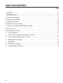
24
INTRODUCTION
Dear Customer,
In purchasing this Voltcraft® product, you have made a very good decision for which we would like
to thank you.
Voltcraft® - In the eld of measuring, charging and network technology, this name stands for
high-quality products which perform superbly and which are created by experts whose concern is
continuous innovation.
From the ambitious hobby electronics enthusiast to the professional user, products from the Voltcraft®
brand family provide the optimum solution even for the most demanding tasks. And the remarkable
feature is: we offer you the mature technology and reliable quality of our Voltcraft® products at
an almost unbeatable price-performance ratio. In this way, we aim to establish a long, fruitful and
successful co-operation with our customers.
We wish you a great deal of enjoyment with your new Voltcraft® product!
All names of companies and products are trademarks of the respective owner. All rights
reserved.

25
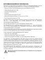
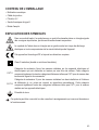
INTENDED USE
Measuring and displaying electric parameters in the range of excess voltage category III (up to max.
600 V against ground potential, pursuant to EN 61010-1) and all lower categories.
• Measuring direct and alternating voltage up to a maximum of 600 V
• Measuring of resistance up to 20 MΩ
• Acoustic continuity check
• Diode test
• Non-contact 230 V/AC voltage test
• Electric current measurement (10 A, mA µA, VC155 only)
• K-type temperature measurement (VC155 only)
The two measuring inputs are secured against overload. The voltage in the measuring circuit may not
exceed 600 V. The measuring ranges are equipped with ceramic high-performance fuses.
The device may only be operated with a 9 V block battery.
The measuring instrument must not be operated when it is open, i.e. with an open battery compartment
or when the battery compartment cover is missing. Measuring in damp rooms or under unfavourable
ambient conditions is not admissible.
For safety reasons, when measuring only use measuring cables or accessories which are adjusted to
the specications of the multimeter.
Unfavourable ambient conditions are:
• Wetness or high air humidity,
• Dust and ammable gases, vapours or solvent,
• Thunderstorms or similar conditions such as strong electrostatic elds etc.
Unauthorised conversion and/or modication of the device are inadmissible because of safety and
approval reasons (CE). Any usage other than described above is not permitted and can damage the
product and lead to associated risks such as short-circuit, re, electric shock, etc. Please read the
operating instructions thoroughly and keep them for further reference.
This product complies with the statutory national and European requirements. All company names
and product names are trademarks of their respective owners. All rights reserved.
Observe all safety instructions and information within this operating manual.

26
DELIVERY CONTENT
• Digital multimeter
• Measuring leads
• 9 V monobloc battery
• K-type thermo sensor (VC155 only)
• Operating instructions
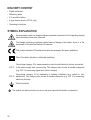
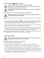
SYMBOL EXPLANATION
An exclamation mark in a triangle indicates important instructions in this operating manual
which absolutely have to be observed.
The triangle containing a lightning symbol warns of danger of an electric shock or of the
impairment of the electrical safety of the device.
This product has been CE-tested and meets the necessary European guidelines.
Class 2 insulation (double or reinforced insulation)
CAT II
Overvoltage category II for measurements on electric and electronic devices connected
to the mains supply with a power plug. This category also covers all smaller categories
(e.g. CAT I for measuring signal and control voltages).
CAT III
Overvoltage category III for measuring in building installation (e.g. outlets or sub-
distribution). This category also covers all smaller categories (e.g. CAT II for measuring
electronic devices).
Ground potential
The symbol can be found when you are to be given tips and information on operation.

27
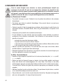
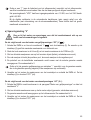
SAFETY INSTRUCTIONS
Read the operating instructions carefully and especially observe the safety
information. If you do not follow the safety instructions and information on proper
handling in this manual, we assume no liability for any resulting personal injury or
damage to property. Such cases will invalidate the warranty/guarantee.
a) Persons / Product
• The device is not a toy. Keep it out of the reach of children and pets.
• Do not leave packaging material lying around carelessly. These may become dangerous
playing material for children.
• Protect the product from extreme temperatures, direct sunlight, strong jolts, high
humidity, moisture, ammable gases, vapours and solvents.
• Do not place the product under any mechanical stress.
• If it is no longer possible to operate the product safely, take it out of operation and protect
it from any accidental use. Safe operation can no longer be guaranteed if the product:
- is visibly damaged,
- is no longer working properly,
- has been stored for extended periods in poor ambient conditions or
- has been subjected to any serious transport-related stresses.
• Please handle the product carefully. Jolts, impacts or a fall even from a low height can
damage the product.
• Also observe the safety and operating instructions of any other devices which are
connected to the product.
b) Batteries / Rechargeable batteries
• Correct polarity must be observed while inserting the batteries.
• Batteries should be removed from the device if it is not used for a long period of time to
avoid damage through leaking. Leaking or damaged batteries might cause acid burns
when in contact with skin, therefore use suitable protective gloves to handle corrupted
batteries.
• Batteries must be kept out of reach of children. Do not leave the battery lying around, as
there is risk, that children or pets swallow it.
• Batteries must not be dismantled, short-circuited or thrown into re. Never recharge
non-rechargeable batteries. There is a risk of explosion!
c) Miscellaneous
• Consult an expert when in doubt about operation, safety or connection of the device.
• Maintenance, modications and repairs are to be performed exclusively by an expert
or at a qualied shop.

28
OPERATING ELEMENTS
See fold-out page
1. HOLD button
2. Non-contact voltage sensor
3. Torch light (Only on VC155)
4. LC display
5. Rotary switch
6. Battery compartment
7. Stand clamp
8. VΩ socket (VC135) / mA µA ºCΩV socket (VC155)
9. COM socket (reference potential)
10. 10A max socket (Only on VC155)
11. Torch button (Only on VC155)
12. BACK LIGHT button (Only on VC155)
DISPLAY INDICATIONS AND SYMBOLS
Battery replacement icon; please replace the battery as soon as possible
Symbol for the diode test
Lightning icon for voltage measuring (VC155 only)
Symbol for the acoustic continuity tester
~ AC Alternating current
DC Direct current
Symbol for active hold function
Ω Ohm (unit of electric resistance)
ºC Unit of temperature
OPERATION
The multimeter (referred to as DMM in the following) indicates measured values on the digital display.
The measuring value display of the DMM spans 2000 counts with VC135 (count = smallest display
value). The measuring device can be used for do-it-yourself or for professional applications (up to
CAT III 600 V). For better readability, the DMM can also be mounted with the clip on the rear.

29
a) Rotary switch (5)
The individual measuring functions are selected via a rotary switch. The measuring range can be
selected manually with this switch.
b) Turning the measuring device on and off
The DMM are turned on and off via the rotary switch (5). When the rotary switch (5) is set to “OFF”, the
DMM is turned off. Always turn the measuring device off when it is not in use.
Prior to working with the measuring device, you rst have to insert the enclosed batteries.
A 9 V block battery is required for voltage supply. This is part of the delivery. Insert the battery as
described in the chapter “Cleaning and Maintenance”.
STARTING THE MEASUREMENT
Do not exceed the maximum permitted input values. Do not contact circuits or parts
of circuits if there could be voltages higher than 25 V ACrms or 35 V DC present
within them. Mortal danger!
Before measuring, check the connected measuring lines for damage such as, for
example, cuts, cracks or squeezing. Defective measuring cables must no longer be
used. Mortal danger!
During measuring, do not grip beyond the tangible grip range markings present
on the test prods.
You may only connect the two measuring leads to the measuring device that are
required for measuring operation. Remove all measuring leads not required from
the device for safety reasons.
As soon as “1” (towards the left side of the display) appears on the display, you have exceeded
the measuring range. Select the next higher measuring range
The voltage range „V/DC“ has an input resistance of >10 MΩ, the V/AC range of >4.5 MΩ.
With the digital multimeter, the automatic range selection (auto range) is active in all measuring
functions (except for currency measuring ranges). This function sets the right measuring range
automatically.

30
a) Voltage measuring “V”
Before measuring voltages, always make sure that the measuring instrument is not
set to a measuring range for current.
Proceed as follows to measure DC voltages “DC” (V ):
1. Turn the DMM on and select the measuring range “V ” with the rotary switch (5). The values on
the rotary switch (5) indicates the maximum measurement value of that selection.
2. Insert the red measuring lead into the V socket (8) and the black measuring lead into the COM
socket (9).
3. Now connect the two measuring prods to the object to be measured (battery, switch etc.).
4. The red measuring tip indicates the positive pole, the black measuring tip the negative pole.
5. The polarity of the respective measuring value is indicated on the together with the current
measuring value. The unit of the measurement is V.
As soon as a minus “-” appears for the direct voltage in front of the measuring value, the
measured voltage is negative (or the measuring tips have been mixed up).
6. After measuring, remove the measuring leads from the measuring object and turn the DMM off.
Turn the rotary switch to the position “OFF” .
Proceed as follows to measure AC voltages (V~):
1. Put the DMM into operation as described in the section “Measuring of direct voltage” and select
the measuring range “V “.
2. Now connect the two measuring leads to the object to be measured (generator, switch etc.).
3. The measuring value is indicated on the display. The unit of the measurement is V.
4. After measuring, remove the measuring leads from the measuring object and turn the DMM off.
Turn the rotary switch to the position “OFF”.
b) Current measuring (A , only in VC155)
The voltage in the measuring circuit may not exceed 250 V.
Measuring operations of >5 A may only be performed for at most 10 seconds with a
subsequent measuring pause of 15 minutes.
All current measuring ranges are provided with fuses and thus protected against
overload.

31
Proceed as follows to measure DC currents “µA, mA, A”
AC current is not supported by this DMM. Do not attempt to measure AC currents
with this DMM.
Insert the red measuring lead into the 10 A max socket (10) if you are not sure about the size
of the current.
1. Turn the DMM on and select the measuring range “A ” with the rotary switch (5). The values
on the rotary switch (5) indicates the maximum measurement value of that selection. Try to start
measuring with the largest measuring range if possible, because the ne fuse will trigger in case
of excess current.
2. Insert the red measuring lead into the 10 A max socket (10) (with currents > 400 mA) or into the
mAμA socket (8) (with currents <400 mA). Plug the black measuring lead into the COM socket.
3. Now connect the two test prods in series with the object to be measured (battery, circuit etc.); the
display indicates the polarity of the measured value together with the currently measured value.
The unit of the measurement is µA, mA or A (depends on the measuring range selected).
As soon as a minus “-” appears for the direct voltage measuring in front of the measuring value,
the measured voltage is negative (or the measuring tips have been mixed up).
c) Resistance measuring
Make sure that all the circuit parts, switches and components and other objects of
measurement are disconnected from the voltage and discharged.
Proceed as follows to measure the resistance:
1. Turn the DMM on and select measuring range “Ω”.
2. Insert the red measuring lead into the Ω socket (8) and the black measuring lead into the COM
socket (9).
3. Check the measuring leads for continuity by connecting both measuring leads to one another. After
that the resistance value must be approximately 0.5 Ω (inherent resistance of the measuring leads).
4. Now connect the measuring prods to the object to be measured. As long as the object to be
measured is not high-resistive or interrupted, the measured value will be indicated on the display.
Wait until the display has stabilised. With resistances of >1 MΩ, this may take a few seconds.
5. As soon as “1” (towards the left side of the display) appears on the display, you have exceeded
the measuring range or the measuring circuit has been broken. Select a larger measuring range
if necessary.
6. After measuring, remove the measuring leads from the measuring object and turn the DMM off.
Turn the rotary switch (5) to the position “OFF”.

32
If you carry out a resistance measurement, make sure that the measuring points which you
contact with the measuring prods are free from dirt, oil, solderable lacquer or similar. An
incorrect measurement may result under such circumstances.
d) Diode test
Make sure that all the circuit parts, switches and components and other objects of
measurement are disconnected from the voltage and discharged.
1. Turn the DMM on and select measuring range with the rotary switch (5).
2. Insert the red measuring lead into the socket (8) and the black measuring lead into the COM
socket (9).
3. Check the measuring leads for continuity by connecting both measuring prods to one another. After
that the value must be approximately 0 V. An acoustic signal can be heard.
4. Now connect the two measuring prods with the object to be measured (diode).
5. The display shows the continuity voltage in volt (V). Open-circuit voltage is about 2.6 V.
6. If “1” (towards the left side of the display) is shown, the diode is measured in reverse direction or
the diode is faulty (interruption). Perform a counter-pole measuring for control reasons. The red
measuring lead corresponds to the positive pole (anode), the black measuring lead to the negative
pole (cathode). A silicone diode has an on-state voltage of approx. 0.5 – 0.8 V. If the diode is place
in the correct direction, an acoustic signal can be heard.
7. After measuring, remove the measuring leads from the measuring object and turn the DMM off.
Turn the rotary switch (5) to the position “OFF” .
e) Continuity test
1. Turn the DMM on and select measuring range with the rotary switch (5).
2. Insert the red measuring lead into the socket (8) and the black measuring lead into the COM
socket (9).
3. Check the measuring leads for continuity by connecting both measuring prods to one another. After
that the value must be approximately 0 V. An acoustic signal can be heard.
4. Now connect the two measuring prods to the two contact points for checking continuity.
5. The display shows the continuity voltage in volt (V).
6. If “1” (towards the left side of the display) is shown, the two contact points are not in a closed circuit.
If the two end points are in a closed circuit, the resistant is less than 10 Ω, an acoustic signal can
be heard.
7. After measuring, remove the measuring leads from the measuring object and turn the DMM off.
Turn the rotary switch (5) to the position “OFF” .

33
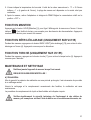
f) Non contact voltage test “NCV”
Make sure that all measuring sockets are unoccupied. Please remove all measuring
leads and adapters from the measuring device.
This function only serves as aid. Prior to performing work on these cables, you
have to perform contact measuring operations to check for the absence of voltage.
1. Turn the DMM on and select measuring range “NCV” with the rotary switch (5). You will see the
word “NCV” on the display (4).
2. Test this function beforehand on a known AC voltage source.
3. Guide the measuring device with the sensor area (3) towards to position to be tested at a distance
of max. 5 mm. In case of twisted cables, it is recommended to check the cable at a length of
approx. 20 to 30 cm.
4. In case voltage is detected, the will be an acoustic signal.
5. After you nish measuring, turn the DMM off. Turn the rotary switch to the position “OFF”.
g) Temperature measuring (only in VC155)
Make sure that all measuring sockets are unoccupied. Please remove all measuring
leads and adapters from the measuring device.
This function only serves as aid. Prior to performing work on these cables, you
have to perform contact measuring operations to check for the absence of voltage.
1. Turn the DMM on and select measuring range “°C” with the rotary switch (5).
2. Disconnect all measuring leads from the measuring instrument.
3. Connect the enclosed temperature sensor to the DMM while observe the correct polarity. The
TEMP (+) terminal must be inserted into the ºC socket (8) and the COM (-) terminal must be
inserted into the COM socket (9).
4. Now expose the sensor tip to the temperatures.
5. The display shows the temperature on the sensor. The unit of the measured value is “ºC”. If “1”
(towards the left side of the display) is shown, the measuring range was exceeded or there is no
sensor connected.
6. After measuring, remove the adapter and turn the DMM off. Turn the rotary switch to the position
“OFF”.
HOLD FUNCTION
The HOLD button (1) allows you to hold the measuring value on the display. The symbol “ ” appears
on the display. This facilitates reading, e.g. for documentation purposes. Another press will switch
back to measuring operation again.

34
BACK LIGHT FUNCTION (ONLY IN VC155)
During any measurement, press the BACK LIGHT button (12) to turn on the back light on the display (4).
Press it again to turn it off.
TORCH FUNCTION (ONLY IN VC155)
During any measurement, press the torch button (11) to turn on the torch light (3). Press it again to
turn if off.
MAINTENANCE AND CLEANING
Never operate the measurement device when it is open.
RISK OF FATAL INJURY!
a) General
To ensure the accuracy of the multimeter over an extended period of time, it should be calibrated
once a year.
Apart from occasional cleaning and fuse replacements, the multimeter requires no servicing.
Information on changing the battery and fuse appears below.
Regularly check the technical safety of the instrument and measuring lines, e.g.
check for damage to the housing or squeezing etc.
b) Cleaning
Live components may be exposed if covers are opened or parts are removed.
The connected lines must be disconnected from the measuring device and all
measuring objects prior to cleaning or repairing the device. Switch the DMM off.
Do not use any carbon-containing cleaning agents or petrol, alcohol or the like to clean the product.
These could corrode the surface of the measuring instrument. Furthermore, the fumes are hazardous
to your health and explosive. Moreover, you should not use sharp-edged tools, screwdrivers or metal
brushes or similar for cleaning.
For cleaning the device or the display and the measuring lines, use a clean, fuzz-free, antistatic
slightly damp cloth.

35
c) Fuse replacement (only for VC155)
Using mended fuses or bridging the fuse holder is not admissible for safety reasons.
Never operate the measurement device when it is open.
RISK OF FATAL INJURY!
The currency measuring ranges are protected against overload with ceramic ne-wire fuses. If
measuring in this range is no longer possible, you have to change the fuse.
Proceed as follows for replacement
1. Separate the connected measuring leads from the measuring circuit and the measuring device.
2. Switch the DMM off.
3. Unscrew the screws on the battery cover, carefully remove the battery cover and battery.
4. Unscrew the two screws on the back of the device and carefully pull the casing apart.
5. Replace the defective fuse with a new fuse of the same type and nominal voltage. The fuses have
the following values:
- F1 ne-wire fuse, quick-action, 0.2 A/600 V (6 x 32 mm), Item no.: 433005.
- F2 ne-wire fuse, quick-action, 10 A/600 V (6 x 25 mm), Item no.: 700161.
6. Now close the housing carefully again.
d) Inserting/replacing the battery
Do not leave at batteries in the device. Even batteries protected against leaking
can corrode and thus release chemicals which may be detrimental to your health or
destroy the battery compartment.
Do not leave batteries lying around carelessly. They might be swallowed by children
or pets. If swallowed, consult a doctor immediately.
If the device is not used for longer periods of time, remove the batteries in order
to prevent leaking.
Leaking or damaged batteries might cause acid burns when getting into contact
with skin. Therefore, use suitable protective gloves.
Make sure that the batteries are not short-circuited. Do not throw batteries into re!
Batteries may not be recharged. Danger of explosion!
Operation of the measuring device requires a 9 V battery (e.g. 1604A). You need to insert a new, charged
battery prior to initial operation or when the battery change symbol appears on the display.

36
To insert/replace the battery, proceed as follows:
1. Separate the connected measuring leads from the measuring circuit and the measuring device.
Switch the DMM off.
2. Unscrew the screw on the rear of the battery compartment (6) and carefully pull the battery cover
and the battery out of the measuring device.
3. Insert a new battery with the correct polarity into the battery cover, insert them into the DMM.
4. Screw and fasten the battery cover with the screw.
You can order suitable alkaline batteries stating the following order no.:
Item no. 65 25 09 (please order one).
Only use alkaline batteries, since these are powerful and have a long life.
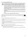
TROUBLESHOOTING
Always observe the safety instructions!
Repairs other than those described should only be carried out by an authorised
specialist.
If you have queries about handling the measuring device, our technical support is
available under the following telephone number:
Voltcraft®, 92242 Hirschau, Lindenweg 15, phone 0180 / 586 582 7
In purchasing the DMM, you have acquired a product which has been designed to the state of the art
and is operationally reliable.
Nevertheless, problems or faults may occur. For this reason, the following is a description of how you
can eliminate possible malfunctions yourself.
Error Possible cause Remedy
The DMM does not
work.
Is the battery dead? Check the status.
No measuring
change.
The HOLD function is activated
(display shows “H”)
Press the button “HOLD” again. The
symbol “H” disappears.
Is the wrong measuring function
active (AC/DC)?
Check the display (AC/DC) and switch
the function if applicable.
Did you use the wrong measuring
sockets?
Check the measuring sockets.
Is the fuse defect? In A/mA/μA range: Change the fuse as
described in the chapter ”Changing the
fuse”.

37
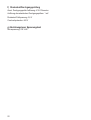
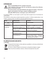
DISPOSAL
a) Product
Electronic devices are recyclable waste and must not be disposed of in the household
waste.
At the end of its service life, dispose of the product according to the relevant statutory
regulations.
Remove any inserted (rechargeable) batteries and dispose of them separately from the
product.
b) Batteries / Rechargeable batteries
You as the end user are required by law (Battery Ordinance) to return all used batteries/rechargeable
batteries. Disposing of them in the household waste is prohibited.
Contaminated (rechargeable) batteries are labelled with this symbol to indicate that
disposal in the domestic waste is forbidden. The designations for the heavy metals
involved are: Cd = Cadmium, Hg = Mercury, Pb = Lead (name on (rechargeable) batteries,
e.g. below the trash icon on the left).
Used (rechargeable) batteries can be returned to collection points in your municipality, our
stores or wherever (rechargeable) batteries are sold.
You thus full your statutory obligations and contribute to the protection of the environment.
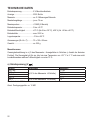
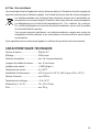
TECHNICAL DATA
Operating voltage ........................ 9 V block battery
Display ......................................... 2000 count
Measuring frequency .................. approx. 2-3 measuring operations/second
Measuring lead length ................. approx. 75 cm
Measuring impedance ................ >10MΩ (V range)
Operation temperature ................ 0 to +40 ºC
Operation humidity ...................... ≤75 % (for 0 to +30 ºC), ≤50 % (for +30 to +40 ºC)
Operating altitude ........................ max. 2000 m
Storage temperature .................... -10 to +50 ºC
Dimensions (W x H x D) .............. 75 x 150 x 38 mm
Weight ......................................... approx. 200 g

38
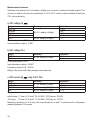
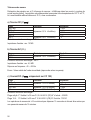
Measurement tolerances
Statement of accuracy in ± (% of reading + display error in counts (= number of smallest points)). The
accuracy is valid for one year at a temperature of +23°C ±5°C, and at a relative humidity of less than
75%, non-condensing.
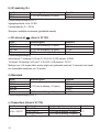
a) DC voltage (V )
Range Accuracy Resolution
200.0 mV
±(0.5 % reading +8 digits)
0.1 mV
2000 mV 1 mV
20.00 V 0.01 V
200.0 V 0.1 V
600 V ±(0.8% reading +8 digits) 1 V
Overload protection: 600 V
Input impedance: approx. 10 MΩ
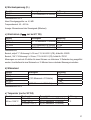
b) AC voltage (V~)
Range Accuracy Resolution
200.0 V
±(1.6% reading +4 digits)
0.1 V
600 V 1 V
Overload protection: 600 V
Input impedance: approx. 4.5 MΩ
Frequency response: 45 – 400 Hz
Display: Sine wave valid value (average value response)
c) DC current (A , only in VC 155)
Range Accuracy Resolution
2000 µA
±(1.3% reading +3 digits)
1 µA
20.00 mA 0.01 mA
200.0 mA ±(1.5% reading +8 digits) 0.1 mA
10A ±(2.6% reading +7 digits) 0.01A
Overload protection:
mAμA range: F1 fuse 6 x 32 mm F 0.2 A H 600 V (CE) Item no.: 433005
10A range: F2 fuse 6 x 25 mm F 10 A H 600 V (CE) Item no.: 700161
Measuring operations of >5 A may only be performed for at most 10 seconds with a subsequent
measuring pause of 15 minutes.

39
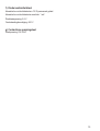
d) Resistance
Range Accuracy Resolution
200.0 Ω
±(1.0% reading +10 digits)
0.1 Ω
2000 Ω 1 Ω
20.00 kΩ 0.01 kΩ
200.0 kΩ 0.1 kΩ
20 MΩ ±(1.3% reading +7 digits) 0.01 MΩ
Overload protection: 600 V
e) Temperature (only in VC 155)
Range Measurement range Accuracy Resolution
-40 to +1000 ºC
-40 to 0 ºC ±(1. 0% reading +10 digits)
1 ºC>0 to +100 ºC ±(3.3% reading +4 digits)
>+100 to +1000 ºC ±(3.9% reading +4 digits)
Overload protection: 600 V
f) Diode / continuity text
Acoustic continuity tester: ≤10 Ω permanent sound
Acoustic continuity tester resolution: 1 mV
Diode test voltage: 2.6 V
Overload protection: 600 V
g) Non-contact voltage test
Target voltage: 230 V/AC
Page is loading ...
Page is loading ...
Page is loading ...
Page is loading ...
Page is loading ...
Page is loading ...
Page is loading ...
Page is loading ...
Page is loading ...
Page is loading ...
Page is loading ...
Page is loading ...
Page is loading ...
Page is loading ...
Page is loading ...
Page is loading ...
Page is loading ...
Page is loading ...
Page is loading ...
Page is loading ...
Page is loading ...
Page is loading ...
Page is loading ...
Page is loading ...
Page is loading ...
Page is loading ...
Page is loading ...
Page is loading ...
Page is loading ...
Page is loading ...
Page is loading ...
Page is loading ...
Page is loading ...
Page is loading ...
Page is loading ...
Page is loading ...
Page is loading ...
Page is loading ...

Impressum
Diese Bedienungsanleitung ist eine Publikation von Voltcraft®, Lindenweg 15, D-92242 Hirschau,
Tel.-Nr. 0180/586 582 7 (www.voltcraft.de).
Alle Rechte einschließlich Übersetzung vorbehalten. Reproduktionen jeder Art, z. B. Fotokopie, Mikroverlmung, oder die Erfassung in
elektronischen Datenverarbeitungsanlagen, bedürfen der schriftlichen Genehmigung des Herausgebers.
Nachdruck, auch auszugsweise, verboten.
Diese Bedienungsanleitung entspricht dem technischen Stand bei Drucklegung. Änderung in Technik und Ausstattung vorbehalten.
© Copyright 2012 by Voltcraft®.
Legal notice
These operating instructions are a publication by Voltcraft®, Lindenweg 15, D-92242 Hirschau/Germany,
Phone +49 180/586 582 7 (www.voltcraft.de).
All rights including translation reserved. Reproduction by any method, e.g. photocopy, microlming, or the capture in electronic data
processing systems require the prior written approval by the editor. Reprinting, also in part, is prohibited.
These operating instructions represent the technical status at the time of printing. Changes in technology and equipment reserved.
© Copyright 2012 by Voltcraft®.
Information légales
Ce mode d’emploi est une publication de la société Voltcraft®, Lindenweg 15, D-92242 Hirschau/Allemagne,
Tél. +49 180/586 582 7 (www.voltcraft.de).
Tous droits réservés, y compris de traduction. Toute reproduction, quelle qu’elle soit (p. ex. photocopie, microlm, saisie dans
des installations de traitement de données) nécessite une autorisation écrite de l’éditeur. Il est interdit de le réimprimer, même par extraits.
Ce mode d’emploi correspond au niveau technique du moment de la mise sous presse. Sous réserve de modications techniques et
de l’équipement.
© Copyright 2012 par Voltcraft®.
Colofon
Deze gebruiksaanwijzing is een publicatie van de rma Voltcraft®, Lindenweg 15, D-92242 Hirschau/Duitsland,
Tel. +49 180/586 582 7 (www.voltcraft.de).
Alle rechten, vertaling inbegrepen, voorbehouden. Reproducties van welke aard dan ook, bijvoorbeeld fotokopie, microverlming of de
registratie in elektronische gegevensverwerkingsapparatuur, vereisen de schriftelijke toestemming van de uitgever. Nadruk, ook van
uittreksels, verboden.
Deze gebruiksaanwijzing voldoet aan de technische stand bij het in druk bezorgen. Wijziging van techniek en uitrusting voorbehouden.
© Copyright 2012 by Voltcraft®.
V3_1012_02-HL
-
 1
1
-
 2
2
-
 3
3
-
 4
4
-
 5
5
-
 6
6
-
 7
7
-
 8
8
-
 9
9
-
 10
10
-
 11
11
-
 12
12
-
 13
13
-
 14
14
-
 15
15
-
 16
16
-
 17
17
-
 18
18
-
 19
19
-
 20
20
-
 21
21
-
 22
22
-
 23
23
-
 24
24
-
 25
25
-
 26
26
-
 27
27
-
 28
28
-
 29
29
-
 30
30
-
 31
31
-
 32
32
-
 33
33
-
 34
34
-
 35
35
-
 36
36
-
 37
37
-
 38
38
-
 39
39
-
 40
40
-
 41
41
-
 42
42
-
 43
43
-
 44
44
-
 45
45
-
 46
46
-
 47
47
-
 48
48
-
 49
49
-
 50
50
-
 51
51
-
 52
52
-
 53
53
-
 54
54
-
 55
55
-
 56
56
-
 57
57
-
 58
58
-
 59
59
-
 60
60
-
 61
61
-
 62
62
-
 63
63
-
 64
64
-
 65
65
-
 66
66
-
 67
67
-
 68
68
-
 69
69
-
 70
70
-
 71
71
-
 72
72
-
 73
73
-
 74
74
-
 75
75
-
 76
76
-
 77
77
-
 78
78


VOLTCRAFT VC135 Operating Instructions Manual
- Category
- Multimeters
- Type
- Operating Instructions Manual
- This manual is also suitable for
Ask a question and I''ll find the answer in the document
Finding information in a document is now easier with AI
in other languages
- français: VOLTCRAFT VC135
- Deutsch: VOLTCRAFT VC135
- Nederlands: VOLTCRAFT VC135
Related papers
-
VOLTCRAFT VC-750E Operating Instructions Manual
-
-
-
VOLTCRAFT R-200 Operating Instructions Manual
-
-
-
-
-
VOLTCRAFT LSG-4 Operating Instructions Manual
-
Other documents
-
Mastech MS8236 User manual
-
Hama 00081700 Owner's manual
-
-
TESTBOY TV 230 User manual
-
MasterChef 670789 User manual
-
Parkside 315848-1904 Operating Instructions And Safety Instructions
-
Eurotops H8130 813 User manual
-
Laserliner MultiMeter-Compact Owner's manual
-
Amprobe AM-HEX60-D Owner's manual
-
Velleman DVM601 User manual